YTPIONEER Electric Side Step User manual

We highly recommend you to find professional store to install the product
I N S T A L L A T I O N M A N U A L
APPLICATION
FJ Cruiser
YEAR
2005+
INSTALLATION TIME 0.5 1 2 3
Installationtime is less than 3 hours depending on proficiency
TOOLS
Attention:
If not follow the instructionmay damage the ECU, motor or the car
Attention:

F J C r u i s e r E l e c t r i c S i d e S t e p 2 0 0 5 +
COMPONENTS LIST
Running board 2 pcs
ECU Signal controller Wire harness:
one set for motor
power and signal
RR idler bracket RF motor bracket LR idler bracket LF motor bracket M10*45 T- shape
screw 8 pcs M8*45 T-shape
screw 4 pcs M6*25 socket
cap screw 8 pcs
Screw package
M10 nut
8 pcs M8 nut
4 pcs U shape washer
10 pcs M10 washer
8 pcs M6 spring washer
8 pcs M8 washer
4 pcs Plastic line 1 Tie wire 20 pcs

F J C r u i s e r E l e c t r i c S i d e S t e p 2 0 0 5 +
Electrical part diagramin
Installation
According to the schematic cable:
1. Take the power supply from the
positive and negative poles of the
battery。
2. Place the control module on the fuse
box inside the cover or in the dry place,
3. From the left and right wheel
eyebrows motor line and signal line to
the chassis

F J C r u i s e r E l e c t r i c S i d e S t e p 2 0 0 5 +
Electrical part installation(The following models are different,
the method is the same)
Open the motor cover ,
get electricity from the battery Put the control box on fuse box
Deploy the cable along the inner side
of left wheel arch Deploy the cable along the inner side
of right wheel arch
Method is common,
not the same model
to display pictures

F J C r u i s e r E l e c t r i c S i d e S t e p 2 0 0 5 +
Harness
1 2
1.Wireless Magnetic Control Signal Transmitter; 2, ECU
with wireless magnetic control signal receiver; 3,
Sponge on the top, middle layer is magnetic sensor,
bottom layer is square magnetic iron. 4, Ink Bottle.
Controller accessories
1---Connectors to the Electric Power; 2/3---
Connectors to the Motors 4---Connector of the
ECU

F J C r u i s e r E l e c t r i c S i d e S t e p 2 0 0 5 +
1
Open the engine bay cover, connect the power cables to the car battery(Note: Red for positive Pole and Black
for Negative Pole), thread the other cables along the Wheel Eyebrow through the nearby holes to the Chassis
bottom, connect the plugs with Motors. The actual operation is showed by following pictures:
Illustration for Cables from engine
bay to Chassis Bottom, connect the
motor cable plug with the motor.

F J C r u i s e r E l e c t r i c S i d e S t e p 2 0 0 5 +
1 Install the sensor and magnetic iron: ①Open the door, find the door sill bar and disassemble it.
At the inner part of the door sill bar, find a
spare position without metal, which is near
outside and backward, stick the sensor there,
make sure the sensor is sticked along the
door sill bar, fix it with 704 silica gel.

F J C r u i s e r E l e c t r i c S i d e S t e p 2 0 0 5 +
1 Install the sensor and magnetic iron: ①Open the door, find the door sill bar and disassemble it.
Pierce the fading ink bottle with
a screw driver, paint the ink on
the sponge, just painting the
ink on the surface is ok, too
much ink is not necessary.
The magnet is attached to the
edge of the mark and the
magnet is now in a position
that matches the magnetic
sensor.

F J C r u i s e r E l e c t r i c S i d e S t e p 2 0 0 5 +
Mechanical part installation
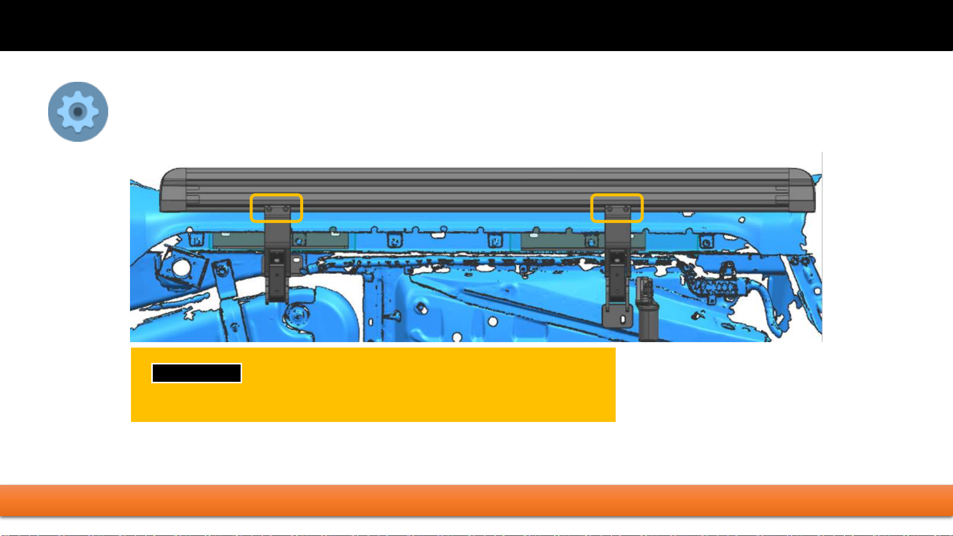
1.Organize the string with tie tape,Install the
removed guard plate in its original position【If
there is interference between the guard plate
and the bracket,the interference part should be
removed】
2.The installation is completed,check whether
there is any omission in the above installation
steps
Disclaimer
Installation must be carried out in accordance
with this manual.The related problems and
losses caused by improper installation and
use are not covered by our warranty

F J C r u i s e r E l e c t r i c S i d e S t e p 2 0 0 5 +
Install running board (2 sides in same way to install)
TIGHTEN SCREWS !!
1 2
1 , 2
Use M6 ×25 screw and spring washers to fix running board with brackets

F J C r u i s e r E l e c t r i c S i d e S t e p 2 0 0 5 +
Testing and adjust the balance
FASTEN ALL THE SCRWS (3 ×4 = 12) ON THE 4 BRACKETS
If still not balance, use U shape washer to adjust it.
Insert fuse again. Then open and close
doors to let step work. To assure them up
and down freely to adjust position by itself.
1 2
3

F J C r u i s e r E l e c t r i c S i d e S t e p 2 0 0 5 +
To changing tire
Automatic power deploy:
The running boards will extend down and out when the door is opened.
Automatic stop:
If an object is in the way of the moving running board, the running board will
automatically stop. To reset, clear any obstruction, then simply open and close the
door to resume normal operation.
Manually set in the deployed (OUT) position for
access to the roof:
Step your foot while at the same time closing the door. To resume normal operation,
open and close the door.
Maintenance:
In adverse conditions, debris such as mud, dirt, and salt may become trapped in the
running board mechanism, possibly leading to unwanted noise. If this occurs,
manually set the running boards to avoid spraying the motors directly. After washing,
apply silicone spray lubricant to the hinge pivot pins.
Caution! Keep hands and feet away when the running board is in motion.
Table of contents
Popular Automobile Accessories manuals by other brands

LinOra
LinOra WIFIRANGER Converge quick start guide

Vivid
Vivid LINQ Superchips user guide

HAUL MASTER
HAUL MASTER 94643 Assembly and operation instructions

GMC
GMC Magne Charge WM7200 installation manual

Kolpin Powersports
Kolpin Powersports Cycle Country 25-1190 Assembly & owners manual

Thule
Thule 1403 Fitting instructions