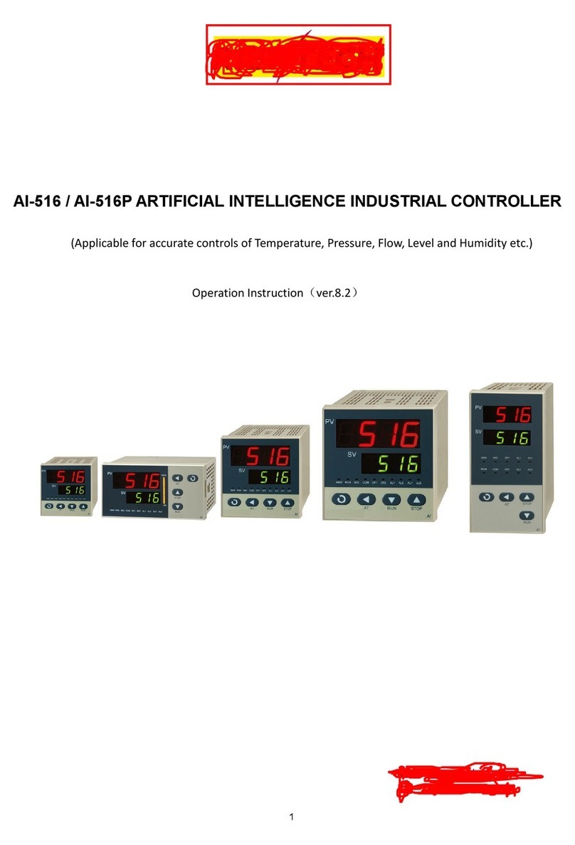
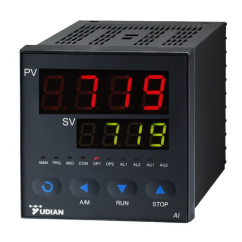
Yudian AI-526 Technical manual

Yudian Automation Technology Co. Ltd.
Website: http://www.yudian.us http://www.yudian.com.hk
Email: sales@yudian.com.hk
Tel: +852-2770 8785 Fax: +852-2770 8796
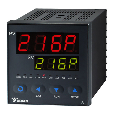
AI-526 / A I -526P
ARTIFICIAL INTELLIGENCE INDUSTRIAL CONTROLLER
Operation Instruction
V e r . 8.2
(Applicable for accurate controls of
Temperature, Pressure, Flow, Level and Humidity etc.)

CONTENTS
1. SUMMARY.............................................................................................................................................................. 1
1.1 MAIN FEATURES 1
1.2 ORDERING CODE DE FINITION 2
1.3 MODULES 5
1.3.1 Slots of modules 5
1.3.2 Commonly used modules: 6
1.3.3 Installation and replacement of modules 7
1.3.4 Electric isolation of the modules 8
1.3.5 Further descriptions about module applications 8
1.4 TECHNICALSPECIFICATION 10
1.5 REAR TE R M I N A L LAYOUT AND WI R I N G 13
2. DISPLAYS AND OPERATIONS...........................................................................................................................17

2.1 FRONT PA N E L DESCRIPTION 17
2.2 PARAMET ER SETTING FL O W CH A R T 19
2.3 OPERATION DESCRIPTION 20
2.3.1 Parameter Setting 20
2.3.2 Set Value Setting 20
2.3.3 Auto Tuning 22
3. PARAMETERS AND SETTINGS.........................................................................................................................24
3.1 PARAMET ER LO C K (LOC)AND FI E L D PARAMET ERS 24
3.2 THE PARAME TER TA B L E 25
3.3 ADDITIONAL REMARKS O F SP E C I A L FUNCTIONS 44
3.3.1 Single-phase phase-shift trigger output 44
3.3.2 Alarm blocking at the beginning of power on 44
3.3.3 Setpoints switch 45

3.3.4 Communication function 45
3.3.5 Temperature re-transmitter / Program generator / Manual current output 46
4. FURTHER DESCRIPTION FOR THE OPERATION O F A I -526P SERIES INSTRUMENT ...........................47
4.1CONCEPTS AND FUNCTIONS PR OGR AM 47
S tE P : 47
StEP time: 47
Running time: 47
Jump: 48
Run/Hold: 48
Stop: 48
Power cut/resume event handling: 48
PV startup and PV preparation function (rdy function) : 49
Curve fitting: 49

5. PROGRAMMING AND OPERATION (FOR AI-526P ONLY) .........................................................................50
5.1 RAMP MODE(PAF :B=0) 50
5.2 SOAK MODE(PAF :B=1) 53
Time setting 53
Program arrangement of multi-curve operation 54

1
1. S UM M AR Y
1.1 Main Features
Use digital calibration technology for input measurement with input measurement accuracy F . S . 0.25%, Support
standard thermocouples and RTDs, maximum resolution is 0.01℃
Use advanced artificial intelligent control algorithm, no overshoot and with the function of auto tuning ( A T ) and
self-adaptation.
Use advanced modular structure, conveniently providing plentiful output options, able to satisfy the requirements
of various applications, make quick delivery and convenience the maintenance of the instrument.
Friendly and customized operating interface leads to quick and easy to operate. Parameter can be promoted to
immediate operator access in Field Parameter Table orpassword protected in Full Parameter Table.
With worldwide power supply of 100-240VAC or 24VDC and various installation dimensions forusers to choose.
ISO9001,CE and UL 61010-1 certified, achieving world class level of quality, anti-interference ability and safety.
POINTS FOR ATTENTION
●This manual is AI-526/AI-526P ARTIFICIAL INTELLIGENCE INDUSTRIAL CONTROLLER Version 8.2.
Certain functions in this manual are probably not applicable for the instrument of other version. When the
power is on, instrument model and software version will be displayed. User should pay attention to the
difference between different versions when using the instrument. Please read this manual carefully in order

2
to use the instrument correctly and make it to its full use.
●Please correctly set parameters according to input / output type and function. Only correctly wired
instruments with parameters correctly set can be put into use.
1.2 Ordering Code Definition
Advanced modularized hardware design is utilized for AI series instruments. There are maximum five module slots:
multi-function input/output (MIO), main output (OUTP), alarm (ALM), auxiliary output (AUX) and communication
(COMM). The modules can be purchased together or individual, and can be assembled freely. The input type can
be set to thermocouple, RTD, or linear current/voltage.
The ordering code o f A I -526/AI-526P (V8.2) series instrument is made up of 9 parts. For example:
AI-526 A N X3 L5 N S4 -24VDC – (F2)
②③④⑤⑥⑦⑧⑨
It shows that the model of this instrument is AI-526, front panel dimension is A s i z e ( 96×96mm), no module is installed
in MIO slot, X3 linear current output module is installed in OUTP (main output), ALM (alarm) is L5 (dual relay contact
output module), no module is installed in AUX (auxiliary output), S4 (RS485 communication interface module) is
installed at COMM , and the power supply of the instrument is 24VDC, an extended input type (F2 radiation type
pyrometer) is available

3
The following is the meaningsof the 9 parts:
①Shows the model of the instrument
AI-526 Economical type instrument with measurement accuracy 0.25% F . S . It adopts artificial intelligent
control technology, and has the functions of control, alarm, retransmission and communication.
AI-526P Base on AI-526 added 30 segments programmable functions.
②Shows the front panel dimension
A(A2) Front panel 96×96mm(width×height), cut out 92×92mm, depth behind mounting surface 100mm.
A2 has a light bar with 25 segments and 4 levels ofluminosity.
BFront panel 160×80mm(width×height), cut out 152×76mm, depth behind mounting surface 100mm.
C(C3) Front panel 80×160mm(width×height), cut out 76×152mm, depth behind mounting surface 100mm.
C3 has an additional light bar with 50 segments and 2 levels of luminosity.
DFront panel 72×72mm(width×height), cut out 68×68mm, depth behind mounting surface 95mm
D2 Front panel 48×48mm(width×height), cut out 45×45mm, depth behind mounting surface 95mm`
EFront panel 48×96mm(width×height), cut out 45×92mm, depth behind mounting surface 100mm
FFront panel 96×48mm(width×height), cut out 92×45mm, depth behind mounting surface 100mm
E5 Rail mounted 48×96×1 1 0 mm(width×height×depth), installed on DIN trail and programmed by
external display E8.

4
③Shows the module type of multiple functions I/O (MIO). Selectable modules are I2, I4, K3 and V, etc. N means
no module been installed.
④Shows the module type of main output (OUTP). Selectable modules are L1,L2,L4,W1,W2,G,K1,K3,K5,K6,X3,X5
etc.
⑤Shows the module type of alarm (ALM). Selectable modules are L1, L2, L4, L5,W1, W2, G, etc.
⑥Shows the module type of auxiliary output (AUX). Selectable modules are L1, L2, L4, L5, W1, W2, G, K1, X3,
X5, etc.
⑦Shows the module type of communication (COMM). Selectable modules are S, S4, V , etc.
⑧Shows the power supply of the instrument. If left blank, the power of the instrument is 100~240VAC. Added
"24VDC" means the power supply of 20~32V DC or AC power
⑨Shows the optional extended graduation spec (If none, leave it blank). AI-526 series instruments support many
input types including popular thermocouples, RTDs, linear voltage, current and resistance inputs. If needed, an
additional specification not mentioned in input type selection (InP) table can be extended.
Note 1: The instrument applies the technology of automatic zero and digital calibration, and is free of maintenance.
If the error exceeds certain range, generally, cleaning and drying the inside of the instrument can fix it. If not, send the
instrument back to the factory to examine and repair.

5
1.3 Modules
1.3.1 Slots of modules
AI-526/526P series instruments have five slots for modules to be installed (D dimension instruments have 3
slots: OUTP, AUX and COMM/AL1; D2 dimension instruments have 2 slots: OUTP and COMM/AUX). By
installing different modules, the controller can meet the requirements of different functions and output types.
Multiple function Input / Output (MIO):
Can input signal from 2-wire transmitter or 4-20mA signal by installing I4 (current input) module and I4 module
can provide 24VDC to transmitter. If a I2 (on-off signal input) module is installed, the instrument can switch
between set points SV1 and SV2 by an external switch. Cooperating with OUTP and installing a K3 module can
realize three-phase thyristor zero cross triggering output.
Main output (OUTP):
Commonly used as control output such as on-off control, standard PID control, and AI PID control. It can be
used as retransmission output of process value (PV) or set point (SV). Installing L1 or L4 modular can realize
relay contact output; installing X3 or X5 module can realize 0-20mA/4-20mA/0-10mA linear current output;
installing G module can realize SSR voltage output; installing W1 or W2 module can implement TRIAC no
contact switch output.

6
Alarm (ALM):
Commonly used as alarm output. Support 1 normally open + normally close relay output (AL1) byinstalling L1 or
L2 module or 2 normally open relay outputs (AL1+AL2) by installing L5 module.
Auxiliary output (AUX): In a heating/refrigerating dual output system, module X3, X5, L1, L4, G, W1, W2 can be
installed for the second control output. It can also output alarm by installing L1, L2 or L5 module, or be used for
communicating with computer by installing R module(RS232C interface).
Communication Interface (COMM): Module S or S4 can be installed in for communicating with computer
(RS485 communication interface), and it can also be used as power supply for external sensor when equipped
with a voltage output module (except for front panel D2 size).
1.3.2 Commonly used modules:
NNo module installed (or null)
L1/L2 Normally open + normally close relay output module (small volume, capacity: 30VDC/1A, 250VAC/1A,
suitable for alarm, L1 modules is 2A)
L4 Large capacity normally open relay output module (large volume, Capacity: 30VDC/2A, 250VAC/2A)
L5 Dual normally open relay output module (Capacity: 30VDC/2A, 250VAC/2A)
W1/W2 TRIAC no contact normally open (W2 is normally close) discrete output module (Capacity:
100-240VAC/0.2A)
GSSR voltage output module (DC12V/30mA)
G5 Dual SSR voltage driver (DC12V/30mA

7
K1 Single-phase thyristor zero crossing trigger output module (can trigger one loop of a TRIAC or a pair of
inverse parallel SCR with current of 5-500A)
K3 Three-phase thyristor zero crossing trigger output module (can trigger 3-phase circuit; each loop can trigger
TRIAC or a pair of inverse parallel SCR with current of 5-500A)
K5/K6 Single-phase 220VAC/380VAC thyristor phase-shift trigger output module (can trigger one loop of TRIAC or
a pair of inverse parallel SCR with current of 5-500A), only 50Hz power
X3/X5 Linear current output module (continuous 0-22mAoutput, selectable in the range of 0-10mA, 4-20mA etc.).
X5 is equipped with photoelectric isolated power supply.
S/S4 RS485 communication interface module. S4 is equipped with photoelectric isolated power supply.
R RS232 communication interface module.
I2 Switch / frequency signal input interface for inputting external switch or frequency signal, has a 12VDC
power supply for external transducer.
I4 4-20mA/0-20mAanalogue input interface, has a 24VDC/24mApower supply for a transmitter.
V24/V12/V10/U5
Isolated 24V/12V/10V/5V DC voltage output with maximum current of 50mA, can supply power for transmitter.
1.3.3 Installation and replacement of modules
Before the instrument delivery, module installation is done on request, with corresponding parameter set correctly.
Users can replace or install modules by themselves when needed. When replacing a module, you should pull the
controller out of the housing at first, insert a small flat-tip screwdriver into the opening between the original module

8
and the slot on motherboard to remove the old module, and then install a new module. Changing module type needs
to modify the corresponding parameters.
1.3.4 Electric isolation of the modules
There are a group of 24V and a group 12V power supply built in the instrument and isolated to the main circuit. The
24V power commonly supplies voltage output module, such as V24/V12/V10/V5, I2 and I4. The 12V power is
commonly supplies output or communication module. Generally, the relay contact output and TRIAC no contact
discrete output are self insulated from the other circuit, no matter whether other modules are installed or not. SSR
output voltage does not need to be insulated from input circuit, because SSR itself has isolation function. Therefore,
only the electric isolation between the communication interface and the current output should be considered. Those
modules, for example, S (RS485 communication interface), R (RS232 communication interface) and X3 (linear current
output), all need the 12V power supply. If more than one of the above modules are installed, in order to be electric
isolated, only one of them can be module without electric isolation, the other modules should be S4 or X5, which has
its own isolated power supply. For example, if an X3 module is installed in OUTP (main output) slot, for isolate
purpose, COMM slot should be install S4 or X5.
1.3.5 Further descriptions about module applications
Voltage output module: The voltage output modules like V24, V12, \/10 or V5 are often used for supplying
power for external transducer or feedback resistance of transmitter. These modules can be installed in any slot.
To standardize the wiring, it is recommended to be installed in the first idle slot in the order of MIO, AUX, and

9
COMM.
No contact switch module: W1 and W2 are new types of no contact switch module which apply the advanced
technology of “burn proof” and zero crossing conduction. It can replace the relay contact switch. Compared to
the relay contact output module, W1 and W2 have longer life and lower interference. They can be largely lower
the interference spark of the equipment, and greatly improve the stability and reliability of the system.
Protection elements are series wound to the output terminals, so it can control continuous current up to 0.2Awith
maximum allowed instantaneous current 2A. Since the driver element is TRIAC, it is suitable for controlling
100-240VAC (not for DC power) with contactor which current below 80A. For the current larger than 80A, an
intermediate relay is needed.
R e l a y switch module: The relay modules are widely used in industrial control. However, they are the only
modules with life time limit and volume limit and have much electromagnetic interference. It is important to
choose a suitable relay module. To control equipments with 100~220VAC supply, such as contactor and
electromagnetic valve, W1 module is recommended. To control DC or AC above 50VAC, users can only use
relay module. L2 module is small, and both its normal open and normal close terminals have the function of
spark absorption, but the capacity is small. It is suitable for alarm output. L1 and L5 have bigger volume and
capacity. In the 48mm dimension instrument (for example, D4, E, F and E5), only one of L1or L5can be installed.
L5 has dual output, can be used to support two loops of alarm, for example, AL1+AL2. If you don’t like
mechanical switch, you can choose G5 (dual SSR voltage driver) and connect with external SSR instead.

10
1.4 TECHNICAL SPECIFICATION
Input type: (Either of below specifications can be used selectively in the one instrument)
Thermocouple: K, S, R, E, J, N, T, B, W R e3-WRe25,WRe5-WRe26.
Resistance temperature detector: Cu50, Pt100
Linear voltage: 0~5V, 1~5 V , 0 ~1V, 0~100mV, 0~2 0 m V , 0~500mV etc.
Linear current (external precise shunt resist needed): 0~10mA,0~20mA, 4~20mA, etc.
Extended input (install I4 module in MIO) : 0~20mA, 4~20mAor two line transmitter.
Optional: apart from the above-mentioned Input type, an additional type can be provided upon request.
(Graduation index is needed)
Instrument Input range
K(-50~1300℃), S(-50~1700℃), R(-50~1700℃), E(0~800℃), J(0~1000℃), N(0~1300℃), T(-200~+350℃),
B(200~1800℃)
Cu50(-50~+150℃), Pt100(-200~+600℃)
Linear Input: -9990~30000 defined by user
Measurement accuracy : 0.25%FS ± 1 measurement unit
Resolution : 0.1℃for K, E, T, N, J, Cu50, Pt100; 1℃for S,R
Temperature shift : ≤0.015%FS /℃(typical value is 80ppm/℃)
Sampling period : readA/D converter 8 times per second

1 1
Response time : ≤0.5s ( when digital filter parameter FILt=0)
Alarm function : High limit, low limit, deviation high limit and deviation low limit; providing the function of alarm
blocking at the beginning of power on.
Control period : 0.24~300.0 seconds selectable, and it should be integer times of 0.5 second.
Control mode:
On-off control mode (dead band adjustable)
Standard PID with auto tuning
AI PID with auto tuning, adopting artificial intelligence algorithm.
Output mode (modularized)
Relay output (NO+NC):250VAC/2A, 30VDC/2A, 250VAC/1A and 30VDC/1A
TRIAC no contact discrete output (NO or NC): 100~240VAC/0.2A (continuous), 2A (20mS instantaneous,
repeat period≥5s)
SSR Voltage output: 12VDC/30mA(used to drive SSR).
Thyristor zero crossing trigger output: Can trigger TRIAC of 5~500A, a pair of inverse paralleled SCRs or
SCR power module.
Linear current output: 0~20mA, 4~2 0 m A can scaling by user. (Output voltage : X3≥10.5V; X5≥7V
maximum load resistor 500ohm, output precision 0.2%FS)
Electromagnetic compatibility (EMC): ±4KV/5KHz according to IEC61000-4-4; 4KV according to
IEC61000-4-5.

12
Isolation withstanding voltage : Between power, relay contact or signal terminals ≥2300VDC; between
isolated electroweak terminals ≥600V
Power supply : 100~240VAC, -15%, +10% / 50-60Hz; 120~240VDC; or 24VDC/AC, -15%, +10%.
Power consumption: ≤5W
Operating Ambient : Temperature 0~60℃; humidity ≤90%RH
Front panel dimension: 96×96mm, 160×80mm, 80×160mm, 48×96mm, 96×48mm, 48×48mm, 72×72mm
Panel cutout dimension: 92×92mm, 152×76mm, 76×152mm, 45×92mm, 92×45mm, 45×45mm, 68×68mm
Depth behind mounting surface: ≤100mm

13
1.5 Rear Terminal Layout and Wiring
Wiring graph of instruments
Note 1: For linear voltage input, if the range is below
500mV, connect to terminals 19 and 18. 0~5V or 1~
5V signal can be inputted from terminals 17 and 18.
Note 2: 4~20mA linear current signal can change to 1~
5V voltage signal by connecting a 250 ohm resistor, and
then be inputted from terminals 17 and 18. If I4 module
is installed in MIO slot, 4~20mA signal can be inputted
from terminals 14+ and 15-, and 2-wire transmitter can be
inputted from terminals 16+ and 14-.
Note 3: The compensation wires for different kinds of
thermocouple are different, and should be directly
connect to the terminals. When the internal auto
compensation mode is used, connecting the common
wire between the compensation wire and the terminals
will cause measurement error.
Note 4: When main output selected linear current or SSR voltage, output form terminal 13+, 11-,
The graph suits for upright instruments
with dimension A or E
For instruments with dimension F or B,
just clockwise rotate the graph 90
degree, and the numbers of the
terminals keep the same.
AU1
M2/MIO
AUX
ALM
COMM
AL2
1
2
3
4
5
6
7
8
9
10
11
12
15
16
17
18
19
20
13
14
AL1
AU2
COM
COM
N/O
N/C
N/O
N/O
+
+
A
B
+
100-240VAC~
+
+
OUTP
COM
COM
N/O
N/C
N/O
N/O
COM
COM
N/O
N/O
N/O
N/C
+
+
OP2
OP1
+
0-5V
1-5V
G1
G2
G1
G2
G1
G2
Thyristor trigger output(K1/K3)
Thyristor trigger output(K3)
Thyristor trigger outuput(K3)
+
COM
N/C
V+
N/O
+
+
+

14
Wiring graph of D dimension instruments (72×72mm)
Note 1: Linear voltage signal of range below 500mV should
be inputted from terminals 13 and 12, and signal of 0~5V
and 1~5V should be inputted from terminals 11 and 12.
Note 2: 4~20mA linear current signal can be converted to
1~5V voltage signal by connecting a 250 ohm resistor and
inputted from terminals 11 and 12.
Note 3: S or S4 module can be installed in COMM slot for
communication. If relay, TRIAC no contact switch, or SSR
drive voltage output module is installed in COMM, it can be
used as alarm output. If I2 module is installed in COMM
and parameter “bAud” is set to 1, SV1 and SV2 can be
switching by connecting a switch between terminals 3 and 4.
AU1
AUX
COMM/AL1
1
2
3
4
5
6
7
8
9
11
12
13
14
10
AU2
COM
COM
N/O
N/C
N/O
N/O
+
+
A
B
+
100-240VAC~
+
+
OUTP
COM
COM
N/O
N/C
N/O
N/O
OP2
OP1
+
0-5V
1-5V
G1
G2
Thyristor trigger output
(K1)
COM
N/O
+

15
Wiring graph of instruments with D2 dimension as below:
Note 1: D4 dimension instruments don’t
support 0~5Vor1~5V linear voltage input.
However, 0~5V or 1~5V signal can be
converted to 0~500mV or 100~500mV by
connecting external precise resistors, 4 ~
20mA can be converted to 100~500mV by
connecting a 25ohm resistor, then be inputted
from terminals 9 and 8.
Note 2: ForCOMM/AUXslot,ifSorS4
communication module is installed, it can be
used for communication; if L2 module is
installed in, parameter set bAud = 0, it can be
used for AU1 or AU2 alarm output; if set
parameter bAud = 2, it can be used for AU1 or AL1 alarm output. If L1, L2, L4, G, K1, W1 or W2 is installed, it can be
the auxiliary output in bidirectional (heating/refrigerating) control (Auxiliary output doesn’t support analog current
output); if I2 is installed and bAud = 1, then it can input on-off signal to switch SP1 and SP2 (AI-526) or switching the
program status RUN / Stop (AI-526P) byconnecting a switch between terminals number3 and 5.
This manual suits for next models
1
Table of contents
Other Yudian Controllers manuals