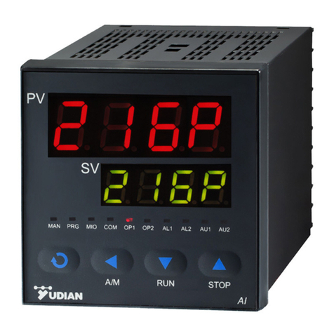
Yudian AI Series Technical manual

AI SERIES ARTIFICIAL INTELLIGENCE INDUSTRIAL CONTROLLER
AI-518/518P Operation Instruction
Ver. 7.1

CONTENTS
1. SUMMARY..............................................................................................................................................................1
1.1 MAIN FEATURES 1
1.2 ORDERING CODE DEFINITION 1
1.3 MODULES 3
New advanced module technology 4
1.4 MENTINANCE 4
2. TECHNICAL SPECIFICATION ...........................................................................................................................4
3. REAR TERMINAL LAYOUT AND WIRING......................................................................................................6
4. DISPLAYS AND OPERATIONS............................................................................................................................8
FRONT PANEL DESCRIPTION 8
4.1 DISPLAY STATUS 8
4.2 OPERATION DESCRIPTION 9
4.2.1 Display status switch 9
4.2.2 Set Value Setting 9
4.2.3 Parameter Setting 9
4.4 PROGRAM OPERATION (FOR AI-518PONLY) 11
4.4.1 Setup program 11
4.4.2 Run/Hold 11
4.4.3 StoP 11
4.4.4 Display and modify the running StEP 11
5. PARAMETERS AND SETTINGS........................................................................................................................12
5.1 THE FULL PARAMETER TABLE 12
5.2 ADDITIONAL REMARKS OF SPECIAL FUNCTIONS 18
5.2.4 Alarm blocking at the beginning of power on(CF.B=1). 19
5.2.5 Sectional power restriction(CF.E=1). 19
6. WIDELY USED CONTROL MODE ...................................................................................................................20
6.1 ON/OFF CONTROL/ALARMING INSTRUMENTS 20
6.2 TEMPERATURE TRAMSMISSION/PROGRAM GIVE GERNATOR20
6.3 AIARTIFICIAL INTELLIGENT REGULATOR 21
7. FURTHER DESCRIPTION FOR THE OPERATION OFAI-518P SERIES INSTRUMENT......................21
7.1 CONCEPTS AND FUNCTIONS21
7.2 PROGRAMMING AND OPERATION EDITTING 22

1
1.SUMMARY
1.1 Main Features
●Adopt digital calibration technology for input measurement with non-linear calibration tables for standard
thermocouples and RTDs are available in the instrument.
●Adopt advanced AI artificial intelligence control algorithm, no overshoot and with the function of auto
tuning and self-adaptation.
●Adopt advanced modular structure, with large numbers of output options. Easy installation to shorten
the assembly time in manufacturing line. Maintenance of instruments make easy.
●Friendly and customized operating interface leads to easy learning and simple manipulation. Any
parameter can be promoted to immediate operator access in Field Parameter Table or password
protected in Full Parameter Table.
●With universal power supply of 100-240VAC or 24VDC and various options of installation dimensions.
●ISO9001 (2000Version),high reliability of quality.
●CE certified, complying with EMC requirement, achieving world class level of quality,
anti-interference ability and safety.
POINTS FOR ATTENTION
●This manual introduces AI-518/518P model ARTIFICIAL INTELLIGENCE INDUSTRIAL CONTROLLER
of Version 7.1. Certain functions may not applicable for other versions. After powering on, the
instrument model and software version will be shown. User should pay attention to the version number.
Please read this manual carefully to ensure proper and safe operation.
●Please correctly set parameters according to input / output specification and function. Only correctly
wired instruments with parameters correctly set should be put into use.
●Compared to Version 6.X or earlier versions, some important changes are: New rear terminal
layout,Heating/refrigerating dual output function, and both outputs can be either current or time
proportional output. Alarm applies single lateral deadband; Support up to 4 channels of alarm or event
outputs; Compared with V7.0, AI-518P has 30segments ramps and soaks with dual editable event
output. Adopted advanced X3/X5 high accuracy current output modules instead of X/X4, it makes
higher transmittion output accuracy.
1.2 Ordering Code Definition
Advanced modularized hardware design is utilized for AI series instruments. There are maximum five
module sockets: multi-function input/output (MIO), main output (OUTP), alarm (ALM), auxiliary output (AUX)
and communication (COMM). The input specification can be selected as thermocouple, RTD, or linear
current/voltage.
The ordering code of AI-708/708P/808/808P series instrument is made up of 8 parts. For example:
AI-518 A N X3 L5 N S4 — F2 -- 24VDC
①②③④⑤⑥⑦⑧
It shows that the model of this instrument is AI-518, front panel dimension is 96×96mm, no module is
installed in MIO (Multi-function I/O) socket, X3 linear current output module is installed in OUTP (main
output), ALM (alarm) is L5 (dual relay contact output module), no module is installed in AUX (auxiliary
output), a RS485 communication interface with photoelectric isolation is installed. It has external expanded
input F2(radiant high thermometer), and the power supply of the instrument is 24VDC.Below is all 10

2
symbols.
①Instrument model
AI-518High accuracy controller with measurement accuracy 0.3%F.S. It adopts artificial intelligent
control technology, and has the functions of control, alarm, retransmission and
communication.
AI-518P Add 30 segment program control to AI-518.
②Front panel dimension
Model Front Panel
(width x
height)
Cut-out
(width x
height)
Depth
Behind
Mounting
Surface
Remarks
A(A2) 96x96mm 92x92mm 100mm
On A2, there is a light bar with 25
segments and 4 levels of luminosity.
B
160X80mm
152x76mm
100mm
C(C3) 80x160mm 76x152mm 100mm
On C3, there is a light bar with 50
segments and 2 levels of luminosity
D
72x72mm
68x68mm
95mm
E
48x96mm
45x92mm
100mm
D2
48x48x110
(width x
height x
depth)
45*45mm 95mm
F
96x48mm
92x45mm
100mm
③Stands for function input module slot MIO, K3,V,U,I2,I4 are able to be plugged in MIO.
④stands for main output (OUTP), can plug in L2,L4,W1,W2,G, K1,K3,X3,X5
⑤Stands for alarm slot(ALM),can add in L2,L4,W1,W2,G, K1,V,U
⑥Stands for auxiliary output(AUX),can add L2,L4,W1,W2,G, K1,K3,X3,X5,V,U,I2
⑦stands for communication(COMM), can add S,S4,V,U
⑧stands for expanded indexing table. AI controllers are defaulted with common used
thermocouple,RTD or current input modules, but if other input signals are needed, can use this
function.
stands for power supply. It’s default as 100~240VAC ,24VDC is available if wanted.
COMMON USED FUNCTION INPUT AND OUTPUT MODULES AS FOLLOWS:
N no module installed
L2 1 relay contact (NO+NC) output.(small size, 30VDC/1A, 250VAC/1A)
L1/L4 1 relay contact (NO+NC) output.(large size, 30VDC/2A, 250VAC/2A)
L5 2 relay contact (NO) outputs. (30VDC/2A, 250VAC/2A)
W1 “Burn-proof”TRIAC no contact normal open output. (100~240VAC/0.2A)
W2 “Burn-proof”TRIAC no contact normal closed output. (100~240VAC/0.2A)
G SSR voltage outputs (12VDC/30mA)
K1 “Burn-proof”single-phase thyristor zero crossing trigger output module (trigger one loop of
a TRIAC or a pair of inverse parallel SCR with current of 5~500A)
K3 “Burn-proof”three-phase thyristor zero crossing trigger output module (trigger 3-phase

3
circuit; each channel can trigger TRIAC or a pair of inverse parallel SCR with current of 5-500A)
K5 “Burn-proof”single-phase thyristor phase-shift trigger output module (trigger one loop of
TRIAC or a pair of inverse parallel SCR with current of 5-500A), suitable for 200~240VAC power
supply.
X3 0~20/4~20mA linear current output module.(Sharing internal 12VDC power)
X5 0~20/4~20mA linear current output module.(With its own isolated power)
S Photoelectric isolated RS485 communication module(sharing internal 12VDC power)
S4 Photoelectric isolated RS485 communication module(with its own isolated power)
V5/V10/V12/V24 Isolated 5V, 10V, 12V or 24V DC output with maximum current 50mA.
U5 Non isolated 5V/25mA voltage output, giving power supply for valve.
I2 on/off switch or frequency signal input, included 12 VDC power for external sensor.
I4 4-20mA/0-20mA analogue input interface, providing a 24VDC/24mA power supply for a
two-wire transmitter.
1.3 MODULES
AI-518/518P series instruments have five sockets for modules .By installing different modules, the controller
expands its functions and output types.
Multiple function Input/Output (MIO): accepts input signal from 2-wire transmitter or 4-20mA signal by
installing I4 (current input) module. If I2 (on-off signal input) module is installed, the instrument can
switch between setpoint SV1 and SV2 by external trigger. If add I2 moudle, AI-518P will be albe to
on/off control programming.With K3, it’s able to give three phase SCR contact zero crossing control
output.
Main output (OUTP): commonly used as control output such as on-off control(CtrL=0), if oP1.A=1,2,4,
then OUTP will be transmittion output forAI-518, programmalbe given output forAI-518P.
Alarm (ALM): commonly used as alarm output. It supports 1 normal open + normal close relay output
(AL1) by installing L1 or L2 module. It supports 2 normal open relay outputs (AL1+AL2) by installing L5
module.
Auxiliary output (AUX): In a heating/refrigerating dual output system, module X3, X5, L1, L4, G, W1,
W2 can be installed as the second control output. It can also output alarm by installing L1, L2 or L5
module, or used for communicating with computer by installing R module (RS232C interface).
Communication Interface (COMM): Module S or S4 can be installed in for communicating with computer
(RS485 communication interface).
Voltage output module: The voltage output modules like V24, \/10 or V12 are often used for supplying
power for external transducer or feedback resistance of transmitter. These modules can be installed in
any socket. To standardize the wiring, it is recommended to be installed in the first idle socket in the
order of MIO, AUX followed by COMM.
Modules installation: usually all modules will be plugged in before sending product to customers.But if
damage happens, users can plug in or take off or change modules by themselves. Re-setting
parameters is needed sometimes, please refer to parameters specially oP,CF.

4
New advanced module technology
1.3.1.Electric isolation among modules: There are built-in power supply unit which is a group of 24V and
12V. They are isolated to the main circuit. The 24V power usually supplies voltage output module, such as
V24/V12/V10, I4 and I5. The 12V power usually supplies output or communication module. Generally
speaking, the relay contact output, TRIAC no contact discrete output and SSR voltage output are
self-insulated. Only the electric isolation between the communication interface and the current output needs
to be pay attention. Those modules, for example, S (RS485 communication interface), R (RS232
communication interface) and X3 (linear current output) all require 12V power supply. If more than one of the
above modules are installed, in order to be electric isolated, only one of them can be module without electric
isolation. The other modules must be S4 or X4, which has its own isolated power supply. For example, if
an X3 module is installed in OUTP (main output) socket, S4 or X5 module is recommended to be installed in
COMM (communication interface) socket, instead of S or X3.
1.3.2.Long life No contact triac switch module : W1 and W2 are new types of no contact switch module
which apply the advanced technology of “burn proof” and zero crossing conduction. It can replace the
relay contact switch. Compared to the relay contact output module, W1 and W2 have longer life and lower
interference. They can largely lower the interference spark of the equipment, and greatly improve the
stability and reliability of the system. Since the driver element is TRIAC, it is suitable for controlling
100-240VAC (not for DC power) with current up to 80A. For the current larger than 80A, an intermediate
relay is needed.
1.4 Mentinance
Annually there will be one time examination for all AI instruments’s quality. If the control accuracy is too
low,usually it’s due to over wet or dust. Clean and clearance is needed. Time won’t influence the accuracy of
AI intruments,so don’t try to change parameter by changing Sc parameter. If problem happens, please
return to YUDIAN factory.
AI controllers are default with 60 days warranty after the data of departure factory.During this period,
free repair is available. Please write down clearly the problem you meet and returns so that can get faster
and correct mentinance.
Any question,you can call at 800-858-2033 free for after sales service.
2.TECHNICAL SPECIFICATION
Input type:
Thermocouple: K, S, R, T, E, J, N, WRe3-WRe25, WRe5-WRe26
Resistance temperature detector: Cu50, Pt100
Linear voltage: 0~5V, 1~5V, 0~1V, 0~100mV, 0~60mV, 0~20mV, etc.; 0~10V if module I31 is
installed on MIO socket.
Linear current (external install I4 module on MIO): 0~20mA, 4~20mA
Extended input is avaliable

5
Instrument Input range
K(-100~1300℃), S(0~1700℃), R(0~1700℃), T(-200~+390℃), E(0~1000℃), J(0~1200℃),
B(600~1800℃), N(0~1300℃), WRe3-WRe25(0~2300℃), WRe5-WRe26(0~2300℃)
Cu50(-50~+150℃), Pt100(-200~+800℃)
Linear Input: -9990~30000 defined by user.
Measurement accuracy : 0.3%FS ± 0.1℃
Resolution : 0.1℃(automatically change to 1℃when the temperature is high than 999.9℃) or 1℃
selectable
Temperature drift : ≤0.01%FS /℃(typical value is 50ppm/℃)
Response time : ≤0.5s ( when digital filter parameter dL=0)
Control mode:
On-off control mode (deadband adjustable)
AI MPT with auto tuning, adopting fuzzy logic PID algorithm.
Output mode (modularized)
Relay output (NO+NC): 250VAC/2A or 30VDC/1A
TRIAC no contact discrete output (NO or NC): 100~240VAC/0.2A (continuous), 2A (20mS
instantaneous, repeat period≥5s)
SSR Voltage output: 12VDC/30mA(used to drive SSR).
Thyristor zero crossing trigger output: can trigger TRIAC of 5~500A, a pair of inverse paralleled
SCRs or SCR power module.
Linear current output: 0~20mA, 4~20mA (The output voltage of X module ≥10.5V; and that of X3
module ≥10.5V.)
Electromagnetic compatibility (EMC) : ±4KV/5KHz according to IEC61000-4-4; 4KV according to
IEC61000-4-5.
Isolation withstanding voltage : between power, relay contact or signal terminal ≥2300VDC;
between isolated electroweak terminals ≥600VDC
Power supply : 100~240VAC, -15%, +10% / 50-60Hz; 120~240VDC; or 24VDC/AC, -15%, +10%.
Power consumption: ≤5W
Operating Ambient : temperature -20~60℃; humidity ≤90%RH
Stock ambient: temperature -30~+70C
Front panel dimension: 96×96mm, 160×80mm, 80×160mm, 48×96mm, 96×48mm, 48×48mm,
72×72mm
Panel cutout dimension: 92×92mm, 152×76mm, 76×152mm, 45×92mm, 92×45mm, 45×45mm,
68×68mm

6
3.Rear Terminal Layout and Wiring
Wiring graph for instruments except D and D2 dimension.
AU1
MIO
AUX
ALM
COMM
AL2
1
2
3
4
5
6
7
8
9
10
11
12
15
16
17
18
19
20
13
14
AL1
AU2
COM
COM
N/O
N/C
N/O
N/O
+
+
A
B
+
100-240VAC~
+
+
OUTP
COM
COM
N/O
N/C
N/O
N/O
COM
COM
N/O
N/O
N/O
N/C
+
+
OP2
OP1
+
0-5V
1-5V
G1
G2
G1
G2
G1
G2
Thyristor trigger output(K1/K3)
Thyristor trigger output(K3)
+
V+
+
+
+
RXD
GND
TXD
The graph suits for upright instruments
with dimension A, C or E
For instruments with dimension F, just
clockwise rotate the graph 90 degree,
and the numbers of the terminals keep
the same.
Note 1: For linear voltage input, if the range is below 1V, connect to terminals 19 and 18. 0~5V or 1~5V
signal can be inputted from terminals 17 and 18.
Note 2: 4~20mA linear current signal can be transformed to 1~5V voltage signal by connecting a 250 ohm
resistor, and then be inputted from terminals 17 and 18. If I4 module is installed in MIO socket, 4~20mA
signal can be inputted from terminals 14+ and 15-, and 2-wire transmitter can be inputted from terminals
16+ and 14-.
Note 3: The compensation wires for different kinds of thermocouple are different, and should be directly
connect to the terminals. When the internal auto compensation mode is used, connecting the common
wire between the compensation wire and the terminals will cause measurement error.
Wiring graph of D dimension instruments
(72×72mm)
Note 1: Linear voltage signal of range below
1mV should be inputted from terminals 13 and
12, and signal of 0~5V and 1~5V should be
inputted from terminals 11 and 12.
Note 2: 4~20mA linear current signal can be
converted to 1 ~5V voltage signal by
connecting a 250 ohm resistor and inputted
from terminals 11 and 12.
Note 3: S or S4 module can be installed in COMM socket for communication. If relay, TRIAC no contact
switch, or SSR driver voltage output module is installed in COMM, it can be used as alarm output. If I2
AU1
AUX
COMM/AL1
1
2
3
4
5
6
7
8
9
11
12
13
14
10
AU2
COM
COM
N/O
N/C
N/O
N/O
+
+
A
B
+
100-240VAC~
+
+
OUTP
COM
COM
N/O
N/C
N/O
N/O
OP2
OP1
+
0-5V
1-5V
G1
G2
Thyristor trigger output(K1)
COM
N/O
+
TXD
RXD
GND

7
module is installed in COMM and parameter “bAud” is set to 1, then on-off signal can be inputted, and SV1
and SV2 can be switched by connecting a switch between terminals 3 and 4.
Wiring graph of D2 dimension instruments (48*48mm)
P.S.:0-5 1-5 is not available ,transfer to 0-500mV or 100-500mV
input. 4-20mA input need add resistant 25ohm so that change to
100-500mV, then connect terminal 9 and 8. Terminal 3.4.5 is
for communcation S,S4. L5 is installed then need change bAud
as 0.
Wiring graph of thyristor trigger output is as below (suitable for module K1, K3, K5 and K6):
Load
Thyristor trigger output
100~380VAC
IN4001
1N4001
Load
Thyristor trigger output
SCR X2
5~500A
BX
BX
Capacitor Resistor
Absorber Circuit
Varistor
G1
G2
G1
G2
ZNR
ZNR
V
V
100~380VAC
TRIAC
5~500A
Capacitor Resistor
Absorber Circuit
Varistor
SCR Power Module
Note 1: According to the voltage and current of load, choose suitable varistor to protect the thyristor.
Capacitor resistor absorber is needed for inductance load or phase-shift trigger output.
Note 2: SCR power module is recommended. A power module includes two SCRs, is similar to the above
dashed square.
Note 3: K1/K3/K5 is burnt free, easy and reliable.
Note 4:Phase-shift trigger module K5 only supports 200~380VAC power, power frequency must be 50Hz.

8
4.DISPLAYS AND OPERATIONS
Front Panel Description
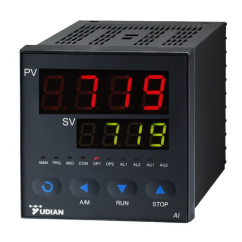
①Upper display window, displays PV,
parameter code, etc.
②Lower display window, displays SV, parameter
value, or alarm
③Setup key, for accessing parameter table and
conforming parameter modification.
④Data shift key, and auto/manual control
switch.
⑤Data decrease key
⑥Data increase key
⑦10 LED indicators. MAN is not used. PRG is
programming condition for AI-518P. MIO,OP1,OP2,AL1,AL2,AU1,AU2 are for input and output.COM is
for communication like PC.
4.1 Display Status
Note: Not all models have the above display status.
When powered on, the unit is in above status①, PV is for measuring value, SV is for given value.
4.2.1When the input signal is out of the measurable range (for example, the thermocouple or RTD circuit is
break, or input specification sets wrong), the lower display window will alternately display “orAL” and the
high limit or the low limit of PV, and the instrument will automatically stop control and set output to 0.

9
4.2.2 If the lower display window alternately display “HIAL”, “LoAL”, “HdAL” or “LdAL”, it means high limit
alarm, low limit alarm, deviation high alarm, and deviation low alarm occurs. The alarm display can also be
turned off by setting parameter “cF”.
4.2.3. For program type instruments AI-518P, run is for common status. the lower display may alternately
display between SV and “StoP”, “HoLd”, or “rdy” which means the program control is stop, pause and ready.
There are 10 indication lights on the front pannel:
“PRG” on indicates program control status, flashing means that the program is in that status of hold or ready,
and off means the program stops.
Light “MAN” on means manual output status, and off means auto control status.
MIO, OP1, OP2, AL1, AL2, AU1 and AU2 respectiviely indicate I/O operation of the corresponding module.
For example, That the COMM indicator is lighting means that the instrument is communicating with
computer.
When current module X or X4 is installed on OUTP socket, the brightness of OP1 and OP2 indicates the
magnitude of the current. When K5 single phase shifting module is installed on OUTP sockets, OP2 on
indicates that the external power is on, and the brightness of OP1 shows the magnitude of phase-shifting
trigger output.
4.2 Operation Description
4.2.1 Display status switch
Depending on the instrument model, press key can switch between different display status.
AI-518P can switch between 1,2,3whileAI-518P can only in 1 ,no need switch.
4.2.2 Set Value Setting
In basic display status, if the parameter lock “Loc” isn't locked, we can set setpoint (SV) by pressing
、or . Press key to decrease the value, key to increase the value, and key to
move to the digit expected to modify. Keep pressing or , the speed of decreasing or inscreasing
value gets quick.
4.2.3 Parameter Setting
In basic display status, press and hold for about 2 seconds can access Field Parameter Table.
Pressing can go to the next parameter; pressing 、or can modify a parameter. Press
and hold can return to the preceding parameter. Press (don't release) and then press key
simultaneously can escape from the parameter table. The instrument will escape auomatically from the
parameter table if no key is pressed within 25 seconds, and the change of the last parameter will not be
saved. In Field Parameter Table, press till the last field parameter “Loc” appears. Setting Loc=808
and then press can access System Parameter Table.Please refer to the table,specially Loc

10
description.
4.3 Auto Tuning
When artificial intelligence MPt control or standard PID control is chosen (CtrL=2), the parameter M5,
P, and t can be obtained by running auto-tuning. In basic display status, press for 2 seconds until “At”
flashes in lower window, and the instrument executes on-off control. After 2 cycles of on-off action, the
instrument will obtain the values of MPt control parameters. If you want to escape from auto tuning status,
press and hold for about 2 seconds until the "At" disappears. Change “At” from “on” to “oFF”, press
to confirm, then the auto tuning process will be cancelled. After the auto tuning is finished, the
instrument will set parameter CtrL to 3 (factory default set is 1) or 4, and now it is not allowed to start up auto
tuning by pressing key on front panel. This will avoid repeat auto tuning by mistake.If you want reset AT,
you can set CtrL to be 2 and re do it.
If the setpoint value is different, the parameter obtained from auto tuning will not always the same. So if
you want to execute auto tuning, you must adjust setpoint to an often-used value first (For AI-518P, set the
value of the current program step to the often-used value), and then start up auto tuning function.
Parameter CtI and dF have influence on the accuracy of auto-tuning. Theoretically, the smaller for these
two parameters setting value, the higher for the precision of auto tuning. But dF parameter value should be
large enough to prevent the instrument from error action around setpoint due to the oscillation of input.
Normally, parameters are recommended to be CtI=0-2, dF=2.0.
On the basis of disturbance caused by on-off control, oscillation period, amplitude and waveform are
analyzed to calculate optimum control parameters. The auto tuning for AI series instrument will gratify for
90% users. Due to the complexity of the automatic process, parameters calculated by auto tuning are
probably not the optimal values on some special occasion (mentioned as follows).
An electric furnace heated up by stages, and the stages may interact each other, then the value of
parameter M5 may on the high side of its optimal value.
Long lagged process.
Quick responded physical quantity (flow and certain pressure) controlled by the slow valve, then the
value of parameter P, t may on the high side of their optimal value. Manual tuning can get better effect.
When some mechanical contact such as contactor or solenoid valve are used for control and parameter
CtI is set too big.
It is not easy to get optimal M5 parameter in refrigerating system and non-temperature system such as
pressure, flow, etc. So set M5 by its definition that M5 is the change of the measurement value when
output change 5%.
Other special system such as nonlinear system and time varying system.
If optimal parameters can’t obtain by auto tuning, M5, P, t parameters can be manually adjusted. During
manual parameter adjustment, response curve of the system should be observed carefully. If it is short
period oscillation (oscillation period is similar to the oscillation of auto tuning), you can decrease P (first), or
increase the value of parameter M5 and t. If it is long period oscillation (oscillation period is several times of
the oscillation of auto tuning), you can increase the value of parameter M5 (first), P and t. None oscillation
but too severe steady-state error, you can decrease M5 (first) and increase P. If it must cost a long period of
time to obtain stable control, you should decrease t (first), M5 and increase P. Any other questions, welcome
to call back to factory.

11
4.4 Program operation (for AI-518P only)
4.4.1 Setup program
Press the key once and release in the display status ①, the instrument will be in the setup program
status. The setpoint of the current program StEP will be displayed. Pressing 、or c can modify
the value. Pressing can go to next parameter. The program parameters will be displayed in the
sequence of setpoint1, time1, setpoint2, time 2, etc... Pressing and holding for about 2 seconds will
return to the previous parameter.
4.4.2 Run/Hold
In display status ①, if the program is in stoP status (“StoP” is alternately displayed on the lower window),
press and hold the key for about 2 seconds until the lower display window displays the "Run" symbol,
the instrument then will start the program. At running status, press and hold the key for about 2
seconds until the lower display window displays the "HoLd" symbol, the instrument changes to hold status.
At Hold status, the program is still executing, and the process value is control led around the setpoint, but
the timer stop working, and the running time and setpoint remains. At Hold status, press and hold the
key for about 2 seconds until the lower display window displays the "Run" symbol, the instrument then
restart.
4.4.3 StoP
Press and hold the key for about 2 seconds in the display status ①until the lower display window
displays the "stoP" symbol, the stoP operation is executed now. This operation forces the instrument to stop
running, and the StEP number is reset to 1, the event output is cleared, the control output is also stopped.
4.4.4 Display and modify the running StEP
Some times it is expected that the program begin with a certain StEP, or jump directly to one StEP and
execute from there. For example, when the current program reaches the 4th StEP but the user wants to
finish the StEP in advance and execute the 5th StEP, then press to switch to program step display
status (display status ③) and modify the program StEP number. If the StEP number is manually changed,
the running time will be cleared to 0 and program will start from the beginning of the new StEP. If the StEP
number is not changed, pressing will escape the program step setting status, and will not affect the
program running.

12
5.PARAMETERS AND SETTINGS
5.1 The Full Parameter Table
Code Name Description
Setting
Range
HIAL High limit alarm
Alarm is triggered when PV (Process Value) >HIAL;
alarm is released when PV<HIAL-dF;
To disable high limit alarm, set HIAL=9999
Every alarm can be defined to controlAL1,AL2,AU1,AU2
-1999~
+9999
units or
1℃
LoAL Low limit alarm
Alarm triggered when PV<LoAL;
alarm released when PV>LoAL+dF
Set LoAL =-1999 can disable low limit alarm
dHAL
Deviation high
alarm
Alarm triggered when PV-SV>dHAL;
alarm released when PV-SV<dHAL-dF
Set HdAL=9999 can disable deviation high alarm.
When on/off control mode is used, dHAL and dLAL is for second high alarm
and low alarm.
0~9999
units or
0~
999.9℃
dLAL
Deviation low
alarm
Alarm triggered when SV-PV>dLAL;
alarm released when SV-PV<dLAL-dF
Set dHAL=9999,when temperature is 999.9C,alarm is cancelled
dF Alarm
hysteresis
Avoid frequent alarm on-off action because of the fluctuation of PV
E.g.: Set HIAL>800C,dF=2.0C
1. in normal status,when HIAL>800C, it alarms
2. in high alarm status, when PV<798C, alarms is cancelled
E.g: Set SV=700c,,dF=2.0C for heating
1.in run status,when PV>700C, it breaks
2.in stop status, when PV<698C, it reheats.
For on/off control mode,,the hgiher dF, the longer period,the lower accuracy.dF
won’t influence AI control. But when do AT, not to make too
high dF. The
adviced dF is 2-3times to PV.
0~2000
units or
0.1℃
CtrL Control mode
CtrL=0: on-off control. For situation not requiring high precision;
CtrL=1: AI MPt control. Allowed to quick activate auto-tuning (pressing
in basic display status.)
CtrL=2:AI MPt control. Activate auto-tuning.
CtrL=3: After auto-
tuning finished, the instrument automatically set CtrL=3, and
quick auto-tuning function is disabled.
CtrL=4: Comparing with the control mode of CtrL=3, Parameter P is defined as
10 times as its original value. Ex., if set P=5 incase of Ctrl=3 and set P=50
incase of Ctrl=5, then these 2 setting have then same control effect. In the
application of rapidly changed temperature (changes by more than 100℃
/second), pr
essure or flow control, or in the application where inverter is used
to control water pressure, P is often very small, even smaller than 1. If CtrL is
set to 4, then parameter P can be enlarged 10 times, and so finer control is
obtained.
0~4

13
M5 Hold parameter
Parameter M5, P, t, CtI etc. are only for AI MPt control, and have no effect
to on-off control.
M5 is defined as measurement variation after output is changed by 5%
(0.5mA if OP1=1) and when controlled process is basically stabilized. "5"
indicates t
hat output variation is 5 (5% or 0.5mA). Generally M5 parameter of
the same system will changes with measurement value, and so M5 parameter
should be configured with process value around operating point.
Take temperature control of electric furnace as an example, the operating
point is 700℃
. To find out optimum M5 parameter, assuming that when out
remains 50%, the temperature of electric furnace will finally be stabilized at
700℃, and when output changes to 55%, the temperature will final be at 750.
Then M5 (optimum parameter)=750-700=50℃
. M5 parameter mainly
determines the degree of integral function, similar as integral time of PID
control. The smaller M5 parameter is, the greater integral function is; where the
larger M5 parameter is, the smaller integra
l function is (integral time is
increased). But if M=0, then integral function an artificial intelligence control
function will be removed and the instrument is turned to be an PD adjustment
that used as a secondary controller during cascade control.
0~9999
units or
0~
999.9℃
P rate parameter
P is in reverse proportion to measurement variations caused by output
changes by 100% in one second. It is defined as the following: if CtrL=1 or 3,
then P=1000/measurement variation per second, the unit is 0.1℃or 1 defined
unit .
Ex., instrument use 100% power to heat and there is no heat loss, if
temperature in crease 1℃
each second, then P=1000/10=100. If CtrL=4, then
P parameter will be configured by increasing 10 times. Ex., P should be set to
1000 in the above example.
1~9999
seconds
t
Lag time
parameter
Parameter t is applied as one of the important parameters of AI artificial
intelligence control algorithm. "t" is defined as follows: time needed for a
electric furnace from the beginning of elevating temperatu
re to get to 63.5%
against the final speed of temperature elevating, provided there is no heat loss.
The unit of parameter “t” is second.
For industrial control, hysteresis effect of the controlled process is an
important factor impairing control effect.
The longer is system lag time, the
more difficult to get ideal control effect. Lag time parameter “t” is a new
introduced important parameter for AI artificial intelligence algorithm. AI series
instrument can use parameter “t” to do fuzzy calculation, and therefore
overshoot and hunting do not easily occurs and the control have the best
responsibility at the time.
The optimal t equals to derivative time in PID control. Parameter “t” gives
effect on proportional, integral and derivative function. If t≤CtI, derivative
function of system will be eliminated.
0~2000
seconds
CtI Control period
The higher Ctl,the stronger ratio.Smaller value can improve control accuracy.
1)For SSR, thyristor or linear current output, generally 0.5~
3 seconds.For
Relay output or i
n a heating/refrigerating dual output control system, generally
15 to 40 seconds, because small value will cause the frequent on-off action of
mechanical switch or frequent heating/refrigerating switch, and shorten its
service life. CtI is recommended to be 1/4 – 1/10 of lag time t, and not greater
than 60 seconds.
2)
For current output, the smaller value can make quicker response,better
control result.
0~125
seconds

14
Sn Input
specification
Code
InP
Input spec.
InP
Input spec.
0
K
20
Cu50
1
S
21
Pt100
2
stock
22
0
~
75mV
3
T
26
0
~
80ohm resistor input
4
E
27
0
~
400ohm resistor input
5
J
28
0
~
20mV voltage input
6
B
29
0
~
100mV voltage input
7
N
30
0
~
60mV voltage input
8
WRe3-WRe25
31
0
~
1V voltage input
9
WRe5-WRe26
32
0.2
~
1V voltage input
10
extended input
specification
33 1~5V voltage input
12
F2 radiation type
pyrometer
34 0~5V voltage input
15
4
~
20mA (installed I4
in MIO)
35 -20~+20mV
16
0
~
20mA (I4 is
installed in MIO)
0~
10V (I31 is
installed in MIO)
36
2
~
10V
37 0~20V
When Sn=10, It means extended input is used. Like R,
WRe325,WR3520,BA1,BA2,G,F2,0-5V, 1-5V.
0~37
dIP
Radix point
position
Four formats (0, 0.0, 0.00, 0.000) are selectable
dIP=0, display format is 0000, no radix point
dIP=1, display format is 000.0
dIP=2, display format is 00.00
dIP=3, display format is 0.000
Note 1: For thermocouples or RTD input, only 0 or 0.0 is selectable, and the
internal resolution is 0.1.
dIP only affect the display, and has no affect to the accuracy of measurement
or control.
0~3
dIL
Signal scale
low limit
Define scale low limit of input. It is also the low limit of external set value,
transmittion output and light bar display.
E.g.:pressure transmitter is used, 1-
5v input,as for 1V input is 0,5V is 1MPa,
hope to be resolution as 0.001MPa. Then you need to set as follows:
Sn=33(1-5v input)
Dip=3(0.000format)
dIL=0.000(input low limit is 1V)
dIH=1.000(input high limit is 5V)
-1999~
+9999
units or
1℃
dIH
Signal scale
high limit
Define scale high limit of input. It is also the high limit of external set value,
retransmission output and light bar display.
Sc Input offset
Sc is used to compensate the error caused by transducer, input signal, or auto
cold junction compensation of thermocouple.
PV_after_compensation=PV_before_compensation + Scb
E.g.:if
input is remaining same, Sc=0.0C, PV=500.0C, when Sc is 10.0, then
PV is 510.0C. Sc is usually 0.
-1.99~
+4000 ℃

15
OP1 output type
OP1 select the control output type:
OP1=OP1.A x 1 + OP1.B x 10
OP1.A shows the output type of OUTP. It should be compatible w
ith the
module installed in OUTP sockets.
OP1.A=0,
if output modules such as SSR voltage output, relay contact
discrete output, thyristor cross zero trigger output, and TRIAC no-contact
discrete output are installed in OUTP.
OP1.A=1, 0~10mA linear curren
t output. Linear current output module
should be installed to main output.
OP1.A=2, 0~
20mA linear current output. Linear current output module
should be installed to main output.
OP1.A=3, spare
OP1.A=4, 4~20mA linear current output. Linear current output module
should be installed to main output.
OP1.A=5~7, is for other models, please not use it forAI-518/518P.
OP1.A=8, single channel phase-
shift output. K5 module should be
installed. AUX can not work as refrigerating output.
OP1.B shows theAUX output type. It works only when parameter oPL<0.
OP1.B=0, time proportional output.
Output modules such as SSR
voltage output, relay contact discrete output, thyristor cross zero trigger output,
and TRIAC no-contact discrete output can be installed in OUTP.
OP1.B=1, 0~
10mA linear current output. Linear current output module
should be installed to main output.
OP1.B=2, 0~
20mA linear current output. Linear current output module
should be installed to main output.
OP1.B=3, spare
OP1.B=4, 4~20mA linear current output.
Linear current output module
should be installed to main output.
AUX does not support position proportional output or phase-
shift trigger
output.
For example, OUT and AUX all output 4~
20mA linear current, then
OP=44.
0~48
OPL Output low limit
0
~
110%: OPL is the minimum output of OUTP in single directional control
system.
-110 ~-
1%: the instrument works for a bidirectional system, and has
heating/refrigerating dual output. When CF.A=0, OUTP (main output) works
for heating, and AUX (Auxiliary output) works for refrigerating. When CF.A=1,
OUTP works for refrigerating, andAUX works for heating.
In a bidirectional system, the heating and refrigerating ability are generally
different.
OPL = -
(power when AUX output is maximum /power when OUTP output is
maximum) x 100%.
For example, for a heating/refrigerating air condition, its maximum power of
refrigerating is 4000W, and maximum power of heating is 5000W, and AUX
works for refrigerating, then
OPL=- (4000/5000)x100% = -80%
The range of AUX output can’t be fre
ely defined by user. If the internal
calculation requires maximum output of AUX (AUX output=OPL), then in 4~
20mA output, the AUX output is 20mA, and user can’t limit the maximum AUX
output to 10mA.
-110~
+110%
OPH
Output upper
limit
OPL limits the maximum of OUTP (main output). OPH should be greater than
OPL.
0~110%

16
ALP
Alarm output
allocation
From right side to left side, the first, second, third and fourth digit of ALP
individually indicate the alarm output terminal of HIAL, LoAL, HdAL, and LdAL.
0 sh
ows no output. 1 and 2 are spare for future use. 3,4,5 and 6
respectively indicate alarms outputted to AL1, AL2, AU1 or AU2. For
example,
ALP = 5 5 0 3
LoAL HdAL LoAL HIAL
It shows that HIAL is sent to
AL1, LoAL has no output, HdAL and LdAL are sent
to AU1.
Note 1: When AUX is used as auxiliary output in bidirectional
(heating/refrigerating) control, alarm to AU1 and Au2 won’t work.
Note 2: Installing L5 dual relay output module in ALM or AUX can implement
AL2 or AU2 alarm.
0~5555
CF System
function
selection
CF is used to select some system function. The value of CF is calculated as
below:
CF=A
×
1+B
×
2+C
×
4+D
×
8+E
×
16+F
×
32+G
×
64+H
×
128
A=0, reverse action control mode. When this mode is selected, an increase in
PV results in a decrease in the control output. Ex, heating control.
A=1,
direct action control mode. When this mode is selected, an increase in
PV results in an increase in the control output. Ex, cooling control.
B=0, without the function of alarm
suppressing at power on or setpoint
changing.
C=0,
When the instrument work as a program generator, the upper window
displays the program step; C=1, it displays PV ( measurement value).(only for
AI-518P)
C=0, When the instrument work within HIAL & LoAL,C=1,SV is not litmited(only
for AI-518,not for AI-518P)
D=0, no remote setpoint input function; D=1,allow remote setpoint input. (only
for AI-518P)
D=0, works as transmittion PV value; D=1,give SV output. (only forAI-518)
E=0, disable the function of sectional power restriction
E=1, enable the function of sectional power restriction
F=0, light bar indicates output value.F=1,
light bar indicates measurement
value
G=0,
When alarm is triggered, the alarm symbol is alternatively displayed on
the lower window. It is helpful for user to know the cause of the alarm.G=1,
disable alarm symbol display.
H=0, unilateral hysteresis is applied; H=1,
bilateral hysteresis is applied (in
order to compatible with old version V6.X).
For example: if it is expected that the instr
ument service as reverse action
control; has the function of alarm suppressing at power on; no restriction on
the range of setpoint; no sectional power restriction; no light bar; alternatively
display alarm symbol when alarming, then we get A=0, B=1, C=1, D=0, E=0,
F=0, G=0,H=0. And so parameter “CF” should be set as follows:
CF=0
×
1 + 1
×
2 + 0
×
4 + 0
×
8 + 0
×
16 + 0
×
32 + 0
×
64 = 2
0~127
Addr
communication
address
In the same communication line, different instrument should be set to different
address.
0~100
bAud
Communication
baud rate
The range of communication baud rate is 1200~19200bit/s. 0~19200

17
dL PV input filter
The value of dL will determine the ability of filtering noise.
There is one intermediate-
value filter system and one second order integral
d
igital filter system in AI series instrument. Intermediate value filter takes
intermediate value among three continuous values, while integral filter has the
same effect as resistance-
capacity integral filter. If measurement input
fluctuates due to noise,
then digital filter can be used to smooth the input.
Parameter “dL” may be configured in the range of 0 to 20, among which, 0
means no filter, 1 means intermediate-value filter and 2~
20 means that
intermediate-value filter and integral filter can be selected simultaneously.
If great interference exists, then you can increase parameter “dF” gradually to
make momentary fluctuation of measured value less than 2 to 5.
When the instrument is being metrological verified, “dF” s can be set to 0 or 1
to shorten the response time.
0~20
run System running
mode
For AI-518P running mode is :
Run=A×1+D×8
Among which: A is used to select 5 kinds of power-
cut event handling
modes; D is used to select 4 kinds of run /modify event-handling modes;
A=0, start to run the
program from step 1 unless the instrument was in “stop”
state before power cut.
A=1,
if these is deviation alarm after power resume, then stop the program,
otherwise, continue to run the program from the original break point.
A=2, continue to run the program from the original break point..
A=3, stop the program.
A=4,
go into HOLD state after power on. If it is in StoP state before power cut,
then keep in StoP State after power on.
D=0, neither PV startup nor PV preparation function. Program is executed as
planed. This mode guarantees constant running time of the program, but it
can’t guarantee the integrity of the whole curve.
D=1, With the function of PV startup and without the function of preparation.
D=2 With the function of preparation and without the function of measurement
value startup.
D=3 With the function of measurement value startup and preparation.
For details about PV startup function and PV preparation function, see program
instruction later chapter.
For example: for one AI-518P, can setA=2,D=3, then we get parameter:
Run=2×1+3×8+0×32=26

18
Loc Parameter lock
If parameter Loc is set to other values than 808, then only field parameters
in the range of 0 to 8 and parameter Loc itself can be set. When parameter Loc
is set to 808, user can set all
parameters. Parameter Loc provides several
operation privileges. When user has completed setting some important
parameters such as input and output, parameter Loc can be set to other values
than 808 in order to avoid field operators’ accidental modificati
on of some
important operation parameters. See the following:
1. for AI-518 series instrument
Loc=0, allowed to modify field parameters and setpoint.
Loc=1,
allowed to view field parameters, and to set setpoint. But the
modification of field parameters (exce
pt parameter Loc itself) is not
allowed.
Loc=2,
allowed to display and view field parameters, but the modification
of field parameters and setpoint (except parameter Loc itself) is not
allowed.
Loc=808, configuration of all parameters and setpoint is allowed.
2. For AI-518P series instrument
Loc=0,
allowed to modify field parameters, program value (time and
temperature value) and program segment number StEP.
Loc=1,
allowed to modify field parameters and StEP value, but the
modification of program is not allowed.
Loc=2,
allowed to modify field parameters, but not allowed to modify StEP
value and program.
Loc=3,
only allowed to modify parameter Loc itself, all other parameters,
program and StEP value can not be modified.
Loc=808, allowed to set all parameters, program and StEP value.
Note:
that 808 is the password of all AI series instrument. In application the
instrument should be set to other values to protect from modifications of
parameters. Meanwhile the management of production should be enforced to
avoid arbitrary operation.
If Loc is set to other values than the above mentioned, the result may be
one of those above mentioned, and most of them are the same as when loc=1
is set.
If you Set Loc to be 808 during field parameter setting, parameter Loc will
automatically turned to be 0 when you finished setting field parameter. If you
set Loc to be 808 after the parameters are unlocked, parameter Loc will be
saved as 808 permanently.
0~9999
EP1
~
EP8
Field
parameter
definition
When parameters are all set, most are not needed to changed and there
maybe damage if wrong parameters are set. Therefore, there is lock function
added. As for AI-
518P,you may need to change parts of ramps values or
times,like HIAL,LoAL etc. 1 to 8 field parameters can be defined by parameters
EP1to EP8. If the number of the field parameters is less than 8, the first idle
EP parameter should be set to “nonE”. Loc=0.EP2=LoAL, EP3=HdAL,
nonE
~run
5.2 Additional Remarks of Special Functions
5.2.1 Time proportional output(oP1=0)
Usually it’s by relay or SSR output voltage high and low proportion to realise the output change. CtL is like
control period. Output is 0%~100%. As for relay output, it’s better set in 20~40seconds, so as to protect
relay life. As for ssr output, it’s better set 0.5~1second so as to achieve best control result. E.g: if want to
make output 20% ~60%, you can set oPL=20,oPH=60. Usually the output is default as oPL=0,oPH=100. No
output limit.
Other manuals for AI Series
1
This manual suits for next models
2
Table of contents
Other Yudian Controllers manuals
Popular Controllers manuals by other brands

Chiyu Technology
Chiyu Technology BF-2300 user guide

Daikin
Daikin DKN-MP130-24M installation instructions

Sony
Sony UPA-PC500 operating instructions

Preferred
Preferred JC-23D2 Installation & operation instructions

Siemens
Siemens CU240E-2 operating instructions

Banner
Banner A-GAGE MINI-ARRAY MAC Series instruction manual

Orbinox
Orbinox VG08 Installation, operation & maintenance manual

bebro electronic
bebro electronic DC RS alpha manual

Prolon
Prolon VC2000 Installation and startup guide

SOMFY
SOMFY Animeo Motor Controller 6 AC IB+ DRM installation guide

Trane
Trane Tracer AH540 Setup and operation

Solarwize
Solarwize RSC-PV1230 user manual