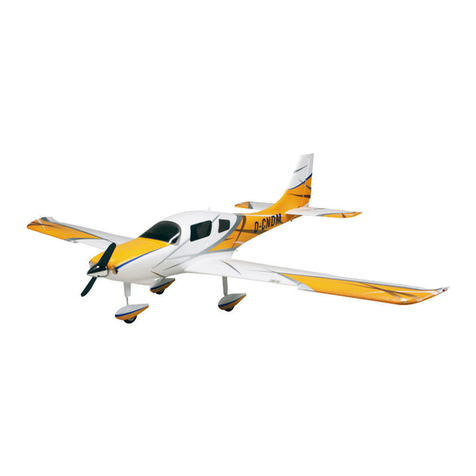
YUKI MODEL EDGE 540 Installation and user guide

EDGE 540
How To +
Anleitung

Spezikationen
Hauptügel Länge 170cm
Länge 153.3cm
Fluggewicht 4.7kg
Flügeläche 49.3 sq.dm
Specications
Main wing length 170mm
Length 153.3cm
Flying Weight 4.7kg
Wing area 49.3 sq.dm
Das Radio-System benötigt 4 Kanäle mit 6 digitalen 6 kg
/ cm Servos. Flugerfahrung für Mittel / Fortgeschrittene.
Die Edge 540, Größe 170cm ist für das Sportiegen und
Kunstug konzipiert.
Danke für Ihr Interesse an unserem Edge 540.
Radio System required 4 channels with 6 digital 6 kg/cm
servos. Flying skill level Intermediate/advanced.
The Edge 540 size 170 is designed for sport ying and
aerobatic ying only.
Thank you for your interested in our Edge 540 airplane.
Please be aware that this aeroplane is not a toy and if
assembled or used incorrectly it is capable of causing
injury to people or property. WHEN YOU FLY THIS AERO-
PLANE YOU ASSUME ALL RISK & RESPONSIBILITY.
Bitte beachten Sie, dass dieses Flugzeug kein Spielzeug
ist und bei falscher Montage oder Benutzung, Verletzun-
gen an Personen oder Eigentum hervorrufen kann. WENN
SIE DIESES FLUGZEUG FLIEGEN, ÜBERNEHMEN SIE
ALLE RISIKEN UND VERANTWORTUNGEN.
Inhalt/Features
Warnung/Warning
• Fertig montiert, minimale Montage & Bearbeitung
erforderlich.
• Fertig beschlagen.
• Foto illustrierte Schritt für Schritt Montageanlei-
tung.
• Ready-made. Minimal assembly & nishing re-
quired.
• Ready-covered covering.
• Photo-Illustrated step by step assembly Manual.

Zusätzliches benötigtes Zubehör / Additional items required
Benötigte Werkzeuge und Hilfsmittel / Tools & pupplies needed
Teileliste / Parts listing
•.1.2 cu.in 2-stroke engine
•4 - 6 digital 6 kg/cm servos
•Glow plug to suit engine
•Propeller to suit engine
•Protective foam rubber for radio system
•Silicone fuel line
• .1.2 cu.in 2-Takt Motor
• 4 - 6 digital 6 kg/cm Servos
• Zündkerze
• Propeller passend zum Motor
• Schutz Schaumgummi für das Radiosystem
• Silikon Treibstoffschlauch
FUSELAGE ASSEMBLY
(1) Fuselage
(1) Canopy hatch
WING ASSEMBLY
(1) Right wing half/ aileron
(1) Left wing half with/ aileron
(1) Aluminium dihedral brace Tail section assembly
(1) Horizontal stabilizer/ elevator halves
(1) Rudder halves
HARDWARE PACK
Cowling
Landing gear
Rumpfmontage
(1) Rumpf
(1) Kabinenhaube
Flügelmontage
(1) Rechte Hälfte / Querruder
(1) Linker Flügel Hälfte mit / Querruder
(1) Aluminium Dieder Klammer Heckteil Montage
(1) Höhenleitwerk / Zughälften
(1) Ruderhälften
HARDWARE PACK
Motorhaube
Fahrwerk
• Thick cyanoacrylate glue
• 30 minute epoxy
• 5 minute epoxy
• Hand or electric drill
• Assorted drill bits
• Modelling knife
• Straight edge ruler
• hexagon screw
• Phillips head screwdriver
• 220 grit sandpaper
• 90° square or builder’s triangle
• Wire cutters
• Masking tape & T-pins
• Thread-lock
• Paper towels
• Dicker Cyanoacrylate Kleber
• 30 Minuten Epoxy
• 5 Minuten Epoxy
• Hand oder Bohrmaschine
• Verschiedene Bohrköpfe
• Modelliermesser
• Lineal
• aussen sechkant
• Kreuzschlitzschraubendreher
• 220er Sandpapier
• 90° Dreieck
• Kabelschneider
• Abdeckband & T -pins
• Schraubensicherung
• Papiertücher

To avoid scratching your new aeroplane we suggest that you
cover your workbench with an old towel. Keep a couple of
jars or bowls handy to hold the small parts after you open the
bags.
Please trial t all parts. Make sure you have the correct parts
and that they t and are aligned properly before gluing! This
will ensure proper assembly as the EDGE 540 is made from
natural materials.
The paint and plastic parts used in this kit are fuel proof. Ho-
wever, they are not tolerant of many harsh chemicals inclu-
ding the following: paint thinner, cyano-acrylate glue accelera-
tor, cyanoacrylate glue de-bonder and acetone.
Um das verkratzen Ihres neuen Flugzeugs zu vermeiden, soll-
ten Sie Ihre Werkbank abdecken. Benutzen Sie Behälter um
Kleinteile aufzubewahren.
Achten Sie darauf, dass die richtigen Teile ordnungsgemäß
vor dem Kleben ausgerichtet sind! Dadurch wird eine fachge-
rechte Montage an der Edge 540 sichergestellt.
Die Lack und Kunststoffteile in diesem Kit wurden einen
Brennstofftest vollzogen. Sie sind jedoch nicht tolerant ge-
genüber vielen, aggressiven Chemikalien wie z.B: Verdünner,
Cyano- Acrylat-Klebstoff Beschleuniger, Sekundenkleber und
Aceton.
1) Carefully remove the aileron from one of the
wing panels. Note the position of the hinges.
2) Remove each hinge from the wing panel and aileron and
place a T-pin in the center of each hinge. Slide each hinge
into the wing panel until the T-pin is snug against the wing
panel. This will help ensure an equal amount of hinge is on
either side of the hinge line when the aileron is mounted to
the aileron.
3) Slide the wing panel on the aileron until there is only a slight
gap. The hinge is now centered on the wing panel and aileron.
Remove the T-pins and snug the aileron against the wing pa-
nel. A gap of 1/64” or less should be maintained between the
wing panel and aileron.
4) Deect the aileron and completely saturate each hinge with
thin C/A glue. The ailerons front surface should lightly contact
the wing during this procedure. Ideally, when the hinges are
glued in place, a 1/64” gap or less will be maintained throug-
hout the lengh of the aileron to the wing panel hinge line.
5) Turn the wing panel over and deect the aileron in the op-
posite direction from the opposite side. Apply thin C/A glue to
each hinge, making sure that the C/A penetrates into both the
aileron and wing panel.
6) Using C/A remover/debonder and a paper towel, remove
any excess C/A glue that may have accumulated on the wing
or in the aileron hinge area.
1) Entfernen Sie das Querruder vorsichtig aus einer der Trag-
ächen. Beachten Sie die Position der Scharniere.
2) Nehmen Sie jedes Gelenk von der Tragäche+Querruder
und setzen Sie ein T-Pin in der Mitte jedes Scharniers. Schie-
ben Sie jedes Scharnier in die Flügelplatte bis der T-Pin direkt
auf der Tragäche sitzt. Dies wird dazu beitragen, eine glei-
che Menge Scharniere beidseits der Gelenke zu haben.
3) Schieben Sie die Tragäche auf das Querruder, bis nur
noch ein kleiner Spalt vorhanden ist. Das Scharnier ist nun
auf der Tragäche und Querruder zentriert. Die T-Pins entfer-
nen und sachte das Querruder gegen die Tragäche drücken.
Eine Lücke von 1/64“ sollte zwischen der Tragäche und
Querruder eingehalten werden.
4) Richten Sie das Querruder und jede Scharniere mit dünnen
C / A- Klebstoff vollständig aus. Die Querruder Vorderäche
sollte den Flügel leicht berühren. Im Idealfall wenn die Schar-
niere angeklebt sind, bendet sich eine 1/64“ Lücke oder we-
niger in der gesamten Länge des Querruders.
5) Drehen Sie die Flügelplatte um und lenken Sie sie Quer in
die entgegengesetzte Richtung aus der gegenüberliegende
Seite. Dünner C / A- Kleber auf jedem Scharnier, um sicher-
zustellen, dass der C / A sowohl in die Querruder und Flügel-
platte eindringt.
6) Mit C / A- Entferner / Bindungslöser und einen Papiertuch
überschüssigen C / A- Klebstoff entfernen.z
Notiz / Note
Anhängen der Querruder / Hinging the ailerons
Hinge.
T- pin. C/A glue.
Hinge.

7) Repeat this process with the other wing panel, securely
hinging the aileron in place.
8) After both ailerons are securely hinged, rmly grasp the
wing panel and aileron to make sure the hinges are securely
glued and cannot be pulled out. Do this by carefully applying
medium pressure, trying to separate the aileron from the wing
panel. Use caution not to crush the wing structure.
7) Wiederholen Sie den Vorgang mit dem anderen Flügel.
8) Nachdem beide Querruder fest angehängt sind, stellen Sie
sicher, dass sie fest geklebt und nicht herausgezogen werden
können.
Anhängen der Höhenruder / Hinging the elevators
Anhängen des Steuerruders / Hinging the rudder
Glue the elevator hinges in place using the same tectniquest
used to hinge the ailerons.
Glue the rudder hinges in place using the same tectniques
used to hinge the ailerons.
Kleben Sie das Höhenruder zusammen, wie bei dem Quer-
ruder.
Kleben Sie das Steurruder zusammen, wie bei dem Querru-
der.
Hinge.

Höhenruder Steuerhorn / Elevator control horn
.
2 sets.
3x45mm.
.
2 sets.
3x45mm.
Aluminum Washer.
CONTRONL HORN M3
M3 LOCK NUT.
Epoxy.
Aluminum Washer.
CONTRONL HORN
M3 SCREW.
ALUMINUM WASHER.
ALUMINUM WASHER.
M3 LOCK NUT.
EPOXY.
16mm.
Epoxy.
Horizontal
Stabilizer.
16mm.
EPOXY.
Fuselage. Rudder.
Elevator control horn.

Steuerruder Steuerhorn / Rudder control horn
Rudder control horn.
Motor Installation / Engine mount installation
Installation der Stopperanordnung / Installing the stopper assembly.
See pictures below.Make yourself the template of your engi-
ne on paper.
Mark and drill 4 holes for engine mount. Insert 4 blind nuts to
rewall.
1) Using a modeling knife, carefully cut off the rear portion of
one of the 3 nylon tubes leaving 1/2” protruding from the rear
of the stopper. This will be the fuel pick up tube.
2) Using a modeling knife, cut one length of silicon fuel line.
Connect one end of the line to the weighted fuel pick up and
the other end to the nylon pick up tube.(The silicon tube is not
included).
3) Carefully bend the second nylon tube up at a 45º angle.
This tube is the vent tube.
Beachten Sie die folgenden Illustrationen und stellen Sie
sicher die richtige Zeichnung für Ihr Motor zu haben.
Markieren und bohren Sie 4 Löcher für die Motor befesti-
gung. Führen Sie anschliessend 4 Blindmuttern ein.
1) Mit Hilfe eines Modellierungs Messer, schneiden Sie vor-
sichtig den hinteren Teil von einem der 3 Nylonrohre ab.Es
sollten 1/2“ von der Rückseite des Anschlags überbleiben.
Dies wird das Kraftstoffaufnahmerohr.
2) Mit Hilfe eines Modellierungs Messers, schneiden sie eine
Länge an Silizium-Kraftstofeitung zu. Schließen Sie das eine
Ende der Leitung an dem Kraftstofffnehmer an und das ande-
re Ende auf die Nylonaufnahmerohre. (Der Silikonschlauch ist
nicht enthalten).
3) Biegen Sie vorsichtig das zweite Nylonrohr in einen 45°
Winkel. Dieses Rohr ist das Entlüftungsrohr.
4x30mm. Diameter =5.5mm.

4) Test t the stopper assembly into thetank. It may be neces-
sary to remove some of the ashing around the tank opening
using a modeling knife. If ashing is present, make sure none
falls into the tank.
5) With the stopper assembly in place, the weighted pick-up
should rest away from the rear of the tank and move freely
inside the tank. The top of the vent tube should rest just below
the top of the tank. It should not touch the top of the tank.
Important: When the stopper assembly is installed in the tank,
the top of the vent tube should rest just below the top surface
of the tank. It should not touch the top of the tank. Carefully
use a lighter or heat gun to permenently set the angle of the
vent tube.
6) When satised with the alignment of the stopper assembly
tighten the 3 x 20mm machine screw until the rubber stopper
expands and seals the tank opening. Do not overtighten the
assembly as this could cause the tank to split.
4) Passen Sie die Anschlagsanordnung testweise an den Be-
hälter an. Es kann notwendig sein, etwas von dem abstehen-
den um die Tanköffnung mit einem Bastelmesser zu entfer-
nen. Wenn Sie etwas von dem abstehenden entfernen, gehen
Sie sicher das nichts in den Tank fällt.
5) Mit der Anschlagsanordnung ausgerichtet, sollten die ge-
wichteten Aufnehmer von der Rückseite des Behälters auie-
gen und sich frei im Inneren des Behälters bewegen können.
Das obere Ende des Entlüftungsrohres ist knapp unterhalb
der Oberseite des Tanks aufgelegt. Sie sollten sich nicht be-
rühren. Wichtig: Wenn die Anschlagsanordnung in dem Tank
installiert ist, sollte das obere Ende des Entlüftungsrohres
knapp unterhalb der Oberseite des Tanks auiegen. Vorsich-
tig mit einem Feuerzeug oder Heißluftpistole, den Winkel des
Entlüftungsrohres befestigen.
6) Wenn Sie mit der Ausrichtung zufrieden sind, ziehen Sie
die 3 x 20 mm Maschinenschraube, bis der Gummi-Stopper
sich ausdehnt und die Tanköffnung abdichtet. Nicht zu fest
anziehen, da dies zur Beschädigung des Tanks führen kann.
Vent tube. Fuel pick up tube.
Fuel fill tube.
Installation des Treibstotanks / Fuel tank installation
Rubber band. Fuel tank.
Fuel pick-up tube.
Fuel fill tube.
Vent tube.
Blasen Sie durch alle Schläuche um sicherzustellen das
sie nicht verstopft sind. Blow through one of the lines to ensure the fuel lines have
not become kinked inside the fuel tank compartment. Air
should ow through easily.

Installation der Batterie / Installing the battery
Battery.
Tie Wrap.
Installation der Räder und Radverkleidung / Wheel and wheel pants installation
1) Assemble and mounting the wheel pants as shown in the
following pictures.
1) Montieren Sie die Radverkleidung wie in den folgenden Bil-
dern.
7mm
14mm
wheel collar.
wheel.
Lite-Plywood
block.
Axle.
Washer.
M3.
M3. wheel Pant.
wheel.
M3.
M3.
wheel collar.
Lite-Plywood
block.
nut. Axle.
Washer.

Landing Gear. wheel Pant.
Locker glue.
2) A drop of C/A glue on the wheel collar screws will help keep
them from coming lose during operation.
1) The blind nuts for securing the landing gear are already
mounted inside the fuselage.
2) Using the hardware provided, mount the main landing gear
to the fuselage.
1) Die Blindmuttern um das Hauptfahrwerk zu sichern, sind im
Rumpf bereits befestigt.
2) Unter Verwendung der Hardware, montieren Sie das
Hauptfahrwerk an den Rumpf.
2) Ein Tropfen C/A -Kleber an den Rad Halsschrauben sichert
sie, damit beim Montieren nichts verrutscht.
Installation des Hauptfahrwerks / Installing the main landing gear
4x20mm.
Locker glue.

Montage des Motors / Mounting the engine
1) Install the pushrod housing through the predrilled hole in
the rewall and into the servo compartment. The pushrod
housing should protrude 1/4“ out past the front of the rewall.
Make a Z-Bend 1/4“ from one end of the plain wire pushrod.
2) Place your engine onto the engine mount. Adjust the engi-
ne is centered of the edges of the engine case.
3) When you are satised with the alignment, mark the loca-
tions of the engine mounting.
4) Remove the engine. Using an drill bit, drill the mounting
holes through the engine mount at the four locations marked.
5) Bolt the engine to the engine mount using the four machi-
ne screws. Double check that all the screws are tight before
proceeding.
6) Attach the Z-Bend in the pushrod wire to the throttle arm on
the carburetor.
1) Installieren Sie das Gestängegehäuse an die vorgebohrten
Löcher. Das Gestängegehäuse sollte 1/4“ aus dem Gehäuse
hervorstehen. Erstellen Sie eine Z-Biegung 1/4“ von einem
Ende der Drahtschubstange.
2) Montieren Sie den Motor an der vorgesehen Motorenbefes-
tigung. Richten Sie ihn in der Mitte des Motoren Gehäuse aus.
3) Wenn Sie zufrieden mit der Platzierung sind, markieren Sie
sie mit einen Stift.
4) Entfernen Sie den Motor. Nehmen Sie eine Bohrmaschine
und bohren Sie 4 Löcher an den angezeichneten Punkten.
5) Schrauben Sie den Motor and die Motorenbefestigung mit
4 Schrauben an. Stellen Sie sicher das alle Schrauben fest
angezogen sind bevor Sie fortfahren.
6) Verbinden Sie die Z-Biegung an dem Zugseil der Druckstan-
ge des Vergasers.
155mm
.
4.2 mm diameter.
Machine Screw 4x30mm.
Pushrod wire.

Installation der Motorhaube / Cowling Installation
1) Slide the berglass cowl over the engine and line up the
back edge of the cowl with the marks you made on the fuse-
lage then trim and cut.
2) While keeping the back edge of the cowl ush with the
marks, align the front of the cowl with the crankshaft of the
engine. The front of the cowl should be positioned so the
crankshaft is in nearly the middle of the cowl opening. Use
the spinner backplate as a guide. Hold the cowl rmly in place
using pieces of masking tape.
3) Install the mufer and mufer extension onto the engi-
ne and make the cut out in the cowl for mufer clearance.
Connect the fuel and pressure lines to the carburetor, mufer
and fuel ller valve. Secure the cowl to fuselage using the
3x10mm screws.
3) Installieren Sie den Schalldämpfer und die Schalldämp-
fer-Erweiterung auf den Motor. Schließen Sie die Kraftstoff-
leitungen und Druckleitungen an den Vergaser, Auspuff und
Tankventil an. Befestigen Sie die Motorhaube am Rumpf mit
den 3x10mm Schrauben.
1) Schieben Sie die GFK-Motorhaube über den Motor und
richten Sie die hintere Kante der Motorhaube an den Markie-
rungen des Rumpfes.
2) Während die hintere Kante der Haube bündig mit den Mar-
kierungen liegt, richten Sie die Vorderseite der Motorhaube
mit der Kurbelwelle des Motors aus. Die Vorderseite der Ver-
kleidung sollte so positioniert werden, dass die Kurbelwelle
nahezu in der Mitte der Windlauföffnung ist. Verwenden Sie
die Spinnergrundplatte als Leitfaden. Halten Sie die Motor-
haube fest an ihren Platz mit Klebeband.
Trim and cut.
Trim and cut.

Installation des Spinners / Spinner installation
Install the spinner backplate, propeller and
spinner cone.
Install the switch into the precut hole in the side of fuselage.
Installieren Sie die Spinner Rückenplatte, Propeller und Spin-
nerkonus.
Installieren Sie den Schalter in das vorgeschnittene Loch an
der seite des Rumpfes.
Machine Screw 3x10mm.
1.5mm were
(needlevalve).
Installation des Spinners / Spinner installation
Switch.

Installation der Rumpf-Servos / Installing the fuselage servo
Installation des Schubarm-Servo / Throttle servo arm installation
1) Install the rubber grommets and brass collets onto the
throttle servo. Test t the servo into the aileron servo mount.
2) Secure the servos with the screws provided
with your radio system.
Install adjustable servo connector in the servo arm.Installieren Sie die einstellbaren Servostecker an den Servo-
hebel.
1) Installieren Sie die Gummiösen und die Messingspannzan-
gen auf das Gasservo.
2) Sichern Sie die Servos mit den mitgelieferten Schrauben
mit Ihrem Funksystem.
Throttle servo
Elevatorservo .
Elevatorservo .
Rudder servo .
AdjustableServo
connector.
Servoarm.
Loctite secure.
1 PCS.
Throttleservo arm.
Elevatorservo .
Elevatorservo .
Rudder servo .

Installation des Schubarm-Servo / Vertical stabilizer installation
Remove the covering a picture shown below.Entfernen Sie die Abdeckung wie in den Bildern gezeigt.
Masking tape.
Removecovering.
Remove the covering.
Fill epoxy.
Remove the covering.
Epoxy.
Hinge slot.

Hinge.
Covering strip.
C/A glue.
Hinge.
Covering strip.

Installation der horizontal Flosse / Installing horizontal n
1) Remove the covering as same as pictures shown below.
2) Sand the aluminium tube using sandpaper. This will impro-
ve the bond of the epoxy to the cardboard horizontal n. Coat
both sides of one half of the aluminium tube with 30 minute
epoxy. Next, pour some epoxy into the cardboard horizontal
n. Use enough epoxy to ll any gaps.
3) Insert aluminium tube into the cardboard
of fuselage.
4) Slide the two horizontal n halves together
and carefully align them at the possition
on the fuselage. Wipe away any excess epoxy
using paper towels.
1) Entfernen Sie die Abdeckung wie in den folgenden Bildern.
2) Schmirgeln Sie das Aluminiumrohr mit Schmirgelpapier.
Dies wird dem Epoxy eine bessere Klebkraft ermöglichen.
Überziehen Sie beide Seiten der Aluminiumrohre mit Epoxy.
Als nechstes benutzen Sie den Epoxykleber an den Tragä-
chen.
3) Führen Sie das Aluminiumrohr in den Rumpf.
4) Schieben sie die zwei Horizontalossen vorsichtig in den
Rumpf. Entfernen sie das überschüssige Epoxy.
Aluminium tube.
335mm.
Epoxy.

Epoxy. Epoxy.
Installation der Querruder-Servos / Installing the aileron servos
Installing the aileron servo in place using the same techniques
used to ap servo.
Instalation der Querruder-Servos wie die Klappen-Servos
Servos. Small weight.
Thread.
String.
Small weight.
Electric wire.
Aileron
Servo.
Attach the string to the servo lead and carefully thread it though the wing.
String. Small Weight.
Wing. Wing rib.
String.
Small Weight.

Querruderschubstange Installation / Aileron pushrod horn installation
Höhenruderschubstange Installation / Elevator - rudder pushrod horn installation
75mm.
M2 lock nut.
M2 clevis.
110mm.
Aileron.
Wing.
Wing.
Aileron.
1) Elevator and rudder pushrods assembly follow pictures be-
low.
1) Für die Installation der Höhenruderschubstange folgen Sie
bitte den Bildern.
M2 Lock nut.M2 clevis.
Attach to servo arm in fuselage. Attach to elevator - rudder control horn.

Elevator.
Rudder.
Throttle.
Control horn.
Elevator Pushrod.
Metal clevis.
M2 lock nut.
Rudder pushrod.
Elevator pushrod.
2) Install servos arm to servos. Notice the position of the servo
arms on the servos. See picture below.
2) Installieren Sie die Gestänge an den Servos. Achten Sie
dabei auf die position wie im folgenden Bild.
Table of contents
Other YUKI MODEL Toy manuals

YUKI MODEL
YUKI MODEL MDM-1 Fox User manual

YUKI MODEL
YUKI MODEL C-400 Cornelius Installation and user guide

YUKI MODEL
YUKI MODEL Blaze 191020 Installation and user guide

YUKI MODEL
YUKI MODEL BEAVER User manual

YUKI MODEL
YUKI MODEL Nimbus 4 Installation and user guide

YUKI MODEL
YUKI MODEL ASW17 Installation and user guide

YUKI MODEL
YUKI MODEL FLY Installation and user guide
Popular Toy manuals by other brands

Fisher-Price
Fisher-Price Ford MUSTANG J4390 Owner's manual & assembly instructions

Mega Bloks
Mega Bloks Barbie Build'n Play Fab Mansion manual

AstroMedia
AstroMedia Hands-on Science Series Building instructions

PARKZONE
PARKZONE PKZ1950 instruction manual

Eduard
Eduard MiG-31B/BS quick start guide

FMS
FMS FMS086P operating manual