YUPACK Ausense FXJ-AT5050 User manual

The automatic folding carton sealer
FXJ-AT5050
Operating instruction
NAME: The automatic folding carton sealer
MODEL: FXJ-AT5050

PREFACE
Thank you for purchasing the automatic folding carton sealer. This
manual will show you the basic struture, using method and points for
attention to use this machine safely and correctly. Please read this manual
carefully before operating the machine.
FX carton sealer seires use OPP tape to seal different kinds of cartons.
The machine is operated and maintained easily with simple structure and
high quality, for which it is widely used in various industries.
Safety precautions
1. The operator and maintenance personnel should read the operating
manual carefully before operating and maintaining this machine.
2. The operator must keep away from the back folding plate to avoid
injury.
3. The power and gas must be closed when installing the tape and doing
the daily maintenance.
4. Only the trained personnel can operate the machine.

Directory
1.Specifications..............................................................................................................1
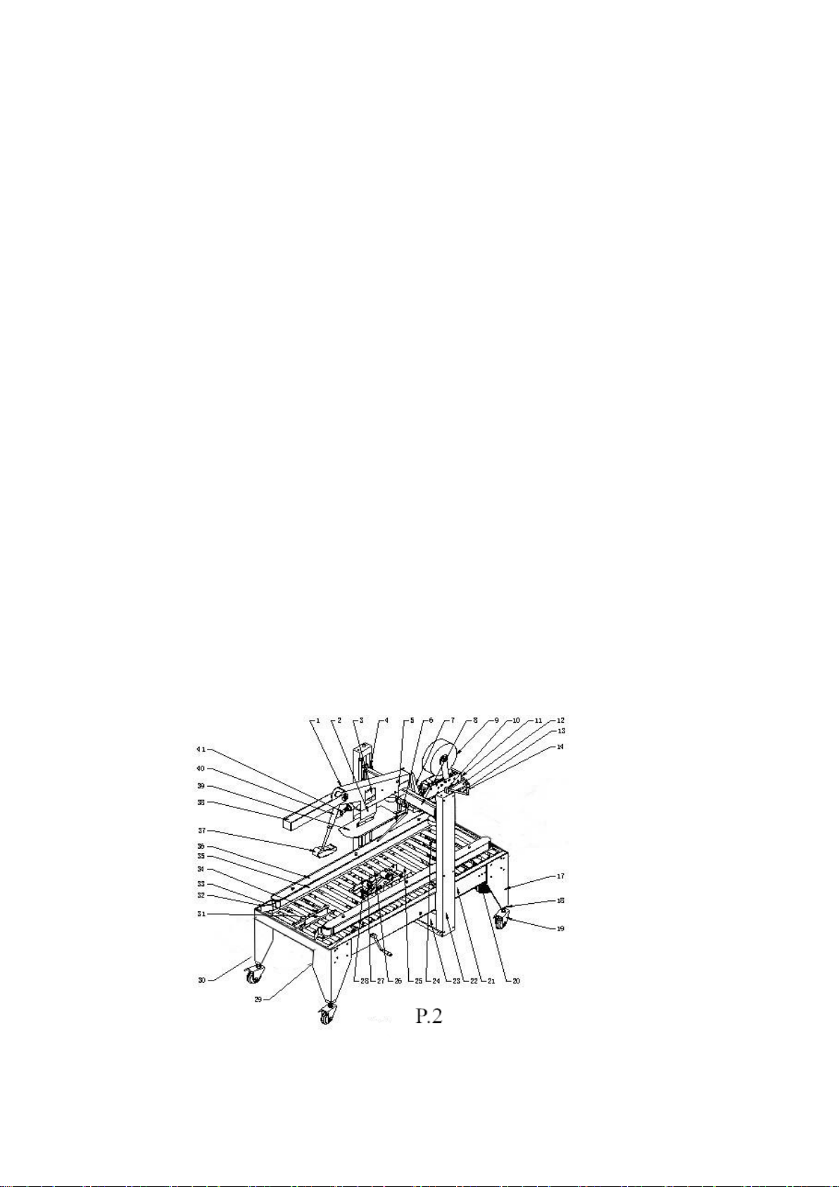
2. Brief introduction of main struture (P.2)....................................................................1
3. Instructions to adjusting parts....................................................................................2
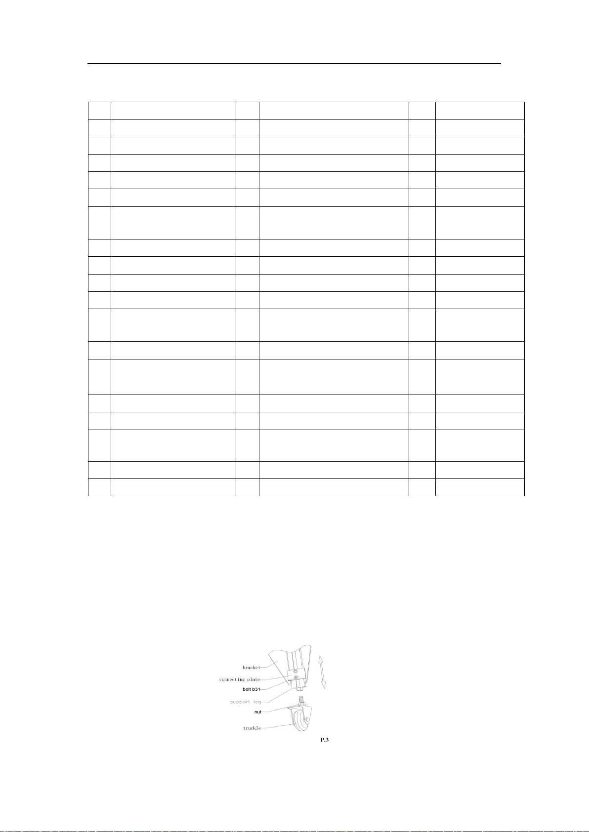
3.1 Table height adjustment (P.3)............................................................................2
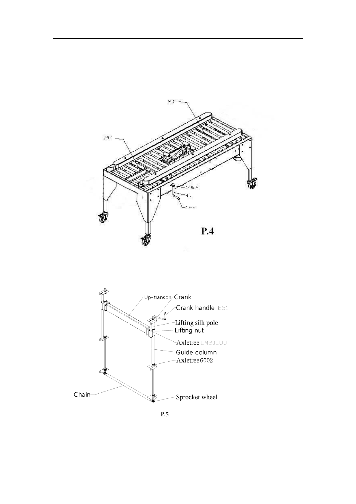
3.2 Width adjustment..............................................................................................3
3.3 Lateral pressure wheel adjustment (P.7) ...........................................................4
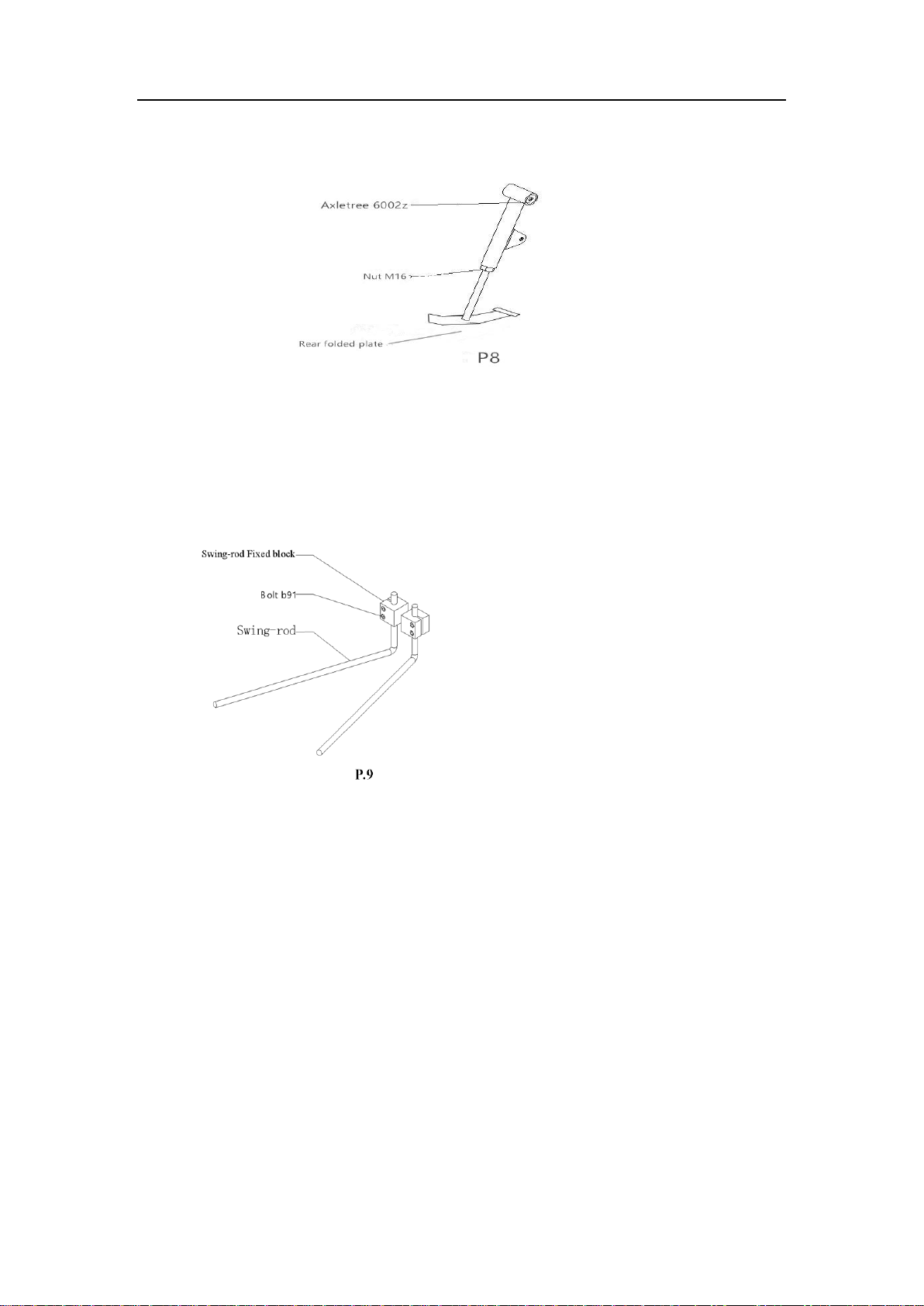
3.4 Back folding plate adjustment (P.8)..................................................................5
3.5 Swing-rod adjustemnet (P.9).............................................................................5
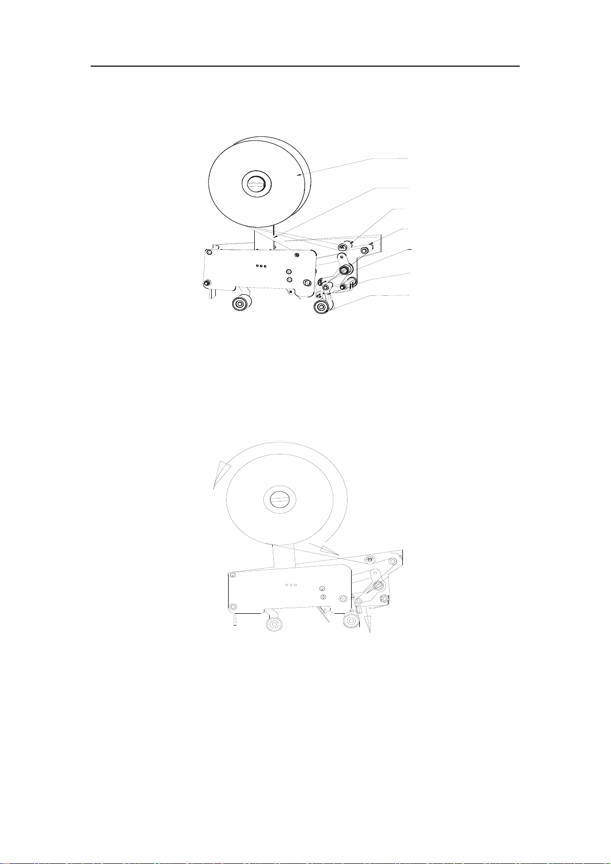
3.6 Adhesive tape installation and adjustment (P.10) .............................................5
4. Operating instruction .................................................................................................8
5. Maintenance...............................................................................................................9
6. Restrictions on cartons...............................................................................................9
7. Exploded figure........................................................................................................10
7.1 General exploded figure..................................................................................10
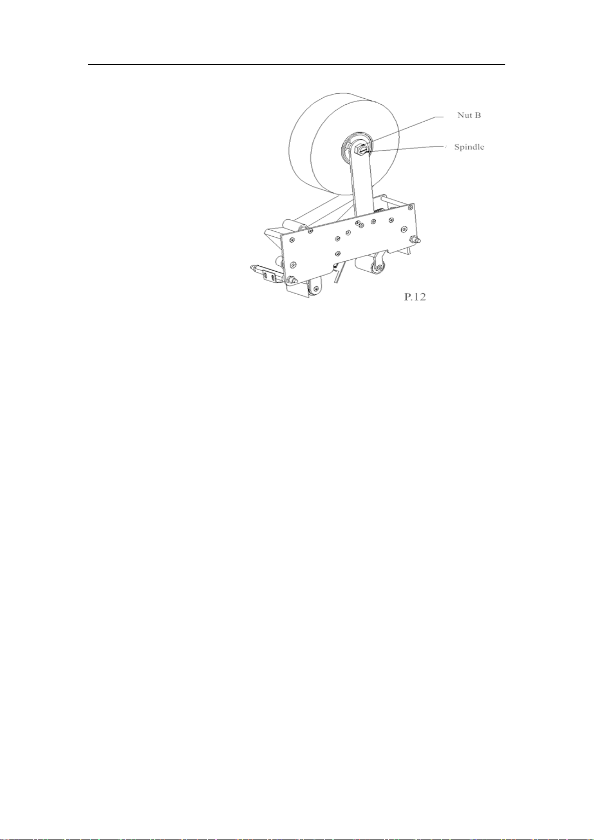
7.2 Exploded figure of adhesive tape adhibiting set.............................................12
8. Malfunctions and solutions......................................................................................14
9. Electric control.........................................................................................................15
9.1 Electric control sketch.....................................................................................15
9.2 Electric control operation................................................................................15
9.3 Inspection and Maintanance of pneumatic control.........................................17
9.4 Inspection and repair of electric control .........................................................17
9.5 Common malfunctions and solutions..............................................................18

1
1.Specifications
The semi-auto folding carton sealer can be operated singlely, with simple operation
and high performance, for which it may be ideal packaging machine for you. The
main specifications are listed as follows:
Sealing width:150mm~500mm
Sealing height:150mm~500mm
Sealing length:200mm~600mm
Table height:610mm~810mm
Machine size:L1700 mm *W950 mm *H1750 mm
Sealing speed:20m/min
Power:220v 50/60HZ
Gas resource: 5.5~6kg/cm2
Applicable tape:W(60~72)mm×L1000y
Machine weight: 200kg
2. Brief introduction of main struture (P.2)

2
Spare parts list:
S/N.
Parts Name
S/N.
Parts Name
S/N.
Parts Name
1
Cylinder holder
19
Truckle
37
Rear folded plate
2
Connecting plate
20
Electromotor
38
Protecting plate
3
Cylinder
21
Right side plate of the frame
39
Front folded plate
4
Lifting nut
22
Column
40
Swing arm
5
Swing-rod
23
Chain protecting cap
41
Spherical bearing
6
Fixed blocks of
swing-rod
24
Rear silk pole
7
Retaining plate
25
Long roller
8
Upper-transom
26
Mid-short roller
9
Adhesive tape roller
27
Lower tape holder
10
Crank fixer
28
Adhesive tape adhibiting set
11
Adhesive tape adhibiting
set
29
Front silk pole
12
Upper tape holder
30
Rear folder controling switch
13
Crank
31
Right side plate of inner frame
14
Crank handle
32
Left-guiding plate
15
Lengthen stand roller
33
Front short roller
16
Lengthen stand
34
Left side plate of inner frame
17
Bracket
35
Strap
18
Support leg
36
Strap left cover board
3. Instructions to adjusting parts
3.1 Table height adjustment (P.3)
Loosen the bolt b31, move the support leg up and down to adjust the table height.

3
3.2 Width adjustment
Shake the crank to adjust the width. Clockwise turn the crank for narrower,
anticlockwise turn the crank for wider. (P.4)
Turing the handle b51 to adjust the height. Clockwise (look out upon )turn the crank
for higher, anticlockwise turn the crank for lower. (P.5)

5
3.4 Back folding plate adjustment (P.8)
3.5 Swing-rod adjustemnet (P.9)
Loosen the nut b91, manually adjust the swing-rod to proper position
3.6 Adhesive tape installation and adjustment (P.10)
1.At first, install the roll of OPP adhesive tape at the core axis (see P.10), pull
out of the adhesive tape, circle around roller B, then circle around roller C, D, get
through tape seating F and get out of the front side of roller G. Pay highly attention
that the side with glutinosity should face toward outside.

6
R oller B
R oller C
Side w ith glutino sity
Co p p e r doller D
Tape hold er F
R oller G
A dh esive tap e ro ller
P .1 0
2.Drawing of the adhesive tape threading (P.11)
P.11
3.Adhesive Tape position adjustment(P.12)
If the adhesive tape is not on the carton central line, please refer to below
picture for adjustment. First, loosen the nut, then move the core axis with nut until
the adhesive tape is moved to the carton central line.

7
4.Adhesive tape tension adjustment
Turn the knob, loosen the nut M8, and adjust the bolt M8*50 to change the
elasticity of swing-rod long extension spring so as to control the tape’s tension..Turn
the knob clockwise and the tension of adhesive tape will largen; turn the knob
anticlockwise, and the tension of adhesive tape will lessen. when the bolt M8*50 is
adjusted frontward, the strain of adhesive tape will largen; conversely, the strain of
adhesive tape will lessen. (P.13)

8
B o lt M 8 *5 0
A dh esiv e tape ro ller
Knob
N u t M 8
S w in g-rod lo ng ex ten sion sprin g
pre - p o s t-
P.13
4. Operating instruction
1. Install and enlace the adhesive tape. Adjust the adhesive tape to the middle position
2. Adjust the air pressure.
3. Check if there is water in the oil-water separator or not.Pipe out the water if has.
Check if the oil is enough. If not, please refuel it.
4. Adjust the sealing height and width
5. Adjust the side pressing wheel
6. Adjust the swing-rod to proper position
7. Connect the power supply, press the ON switch to run the machine.
8. Push the carton onto the worktable (the covers of the carton must be pricked up),
and loosen your hand when the carton is brought along by the conveyer belt. when the
carton touches the back folder controling switch, the piston of the cylinder will hold
out to push up the back folder. After the whole carton passes the back folder
controling switch, the back folder will fall down and press the back cover of the
carton. At the same time, the side covers of the carton are folded by the swing-rod.
Then the folding and sealing is finished.
9. The folding order: front cover, back cover, side covers

9
10. Press the OFF switch to stop the machine.
5. Maintenance
1. The power and gas must be cut off when maintenance or adjustment is carried out.
2. Check if the oil of the oil-water separator is enough or not.Refuel promptly. it must
use the special oil for air pressure and never use other kinds of replacing oil.
3. Check the water filtration cup of the oil-water separator to make sure there is
appropriate water in it.
4. Often brush the axis to prevent dust filtering into the piston, which may cause gas
leaking.
5. Maintenance of the air pressure pipe: If the air pressure pipe need to be uninstalled
for maintanance, please notice that if the pipe is bent or not before installation.
Straighten it if bent for avoiding air obstruction.
6. Fill the engine oil to the silk pole every 3 months.
7. Fill the engine oil to the chain every 3 months
8. Please keep the machine clean and dry.
9. The power supply and gas must be cut off when maintenance or adjustment is
advanced.
10. The reamer patch must be cleaned and lubricated before use.
11. It’s normal that the strap would be tightened after operating for some time.
12. If any malfunction occur under correct operation within 1 year, we will provide
the fittings for free.
6. Restrictions on cartons
1. Don’t use the carton with plastic film on the surface.

10
2. The carton must be dry. (Wet carton can’t be sealed)
3. No dust and garbage are allowed on the surface of the carton
4. Deformed cartons are prohibited for use.
5. The adhesive tape with different width and thickness can’t be used
6. The adhesive tape which is produced for half a year is not suggested to use.
7. Exploded figure
7.1 General exploded figure
37
38
36
34
22
20
16
15
25
4
5
6
8
18
17
12
19
21
11
26
27
29
28
30
31
32
33
9
7
10
13
14
23
24
35
P .1 4

11
Parts list
NO.
Parts Name
NO.
Parts Name
1
Electromagnetic valve
21
Dextrorotation nut
2
Upper-adhesive tape
adhibiting set
22
Post-silk pole
3
Upper-adhesive tape
adhibiting set fixed
block
23
Sprocket wheel
4
Side covered plate
24
Axis sheath
5
Handle
25
Driver
6
Lateral pressure wheel
fixed block
26
Motor connecting axis
7
Lateral pressure wheel
leader
27
Axis sheath
8
Lateral pressure wheel
axis
28
Motor connecting plate
9
Lateral pressure wheel
29
Motor
1/4P 220V 1450RMP I=1:18
10
Lengthen left plate
30
Strap holder
11
Lengthen roller axis
31
Switch
12
Lengthen roller
32
Post-folder controled switch
13
Long roller axis
33
Short pre-roller axis
14
Roller bolt
34
Pre-silk pole
15
Acorn nut
35
Transmission axle
16
Transmission wheel
36
Electrical box
17
Roller plug
37
Mid-short roller axis
18
Transmission axle
38
Mid-short roller
19
Connecting axis
groupware
39
Lower-adhesive tape adhibiting set
20
Left lateral nut
40
Oil-water segregator

12
7.2 Exploded figure of adhesive tape adhibiting set
Parts list:
NO.
Parts Name
NO.
Parts Name
1
Screw M4*12
53
Swing-rod fixed axis
2
ScrewM5*16
54
Swing-rod long extension spring
3
ScrewM5*20
55
Fixed block
4
ScrewM6*12
56
Fixup axis
5
ScrewM6*16
57
Orientation spring
6
ScrewM6*20
58
Rubber wheel axis
7
ScrewM8*16
59
Rubber wheel
8
ScrewM8*16
60
Orientation rubber wheel
9
ScrewM8*50
61
Rubber wheel sheath
10
boltM5*8
62
Pre-pressing floral whorl
11
bolt5*16
63
Pre-pressing floral whorl axis
12
boltM6*12
64
Pre-pressing floral whorl axis spring
13
boltM6*20
65
Pre-pressing floral whorl gasket
14
ScrewM3*8
66
Strap protecting bracket axis
15
ScrewM3*5
67
Strap protecting bracket spring
16
ScrewM4*8
68
Protecting cap fixed plate
17
ScrewM4*10
69
Right stator
18
ScrewM5*8
70
Left stator
19
ScrewM5*50
71
Guide plate
20
ScrewM5*8
72
Fixed haulm sheath
21
Retainer ring 5
73
Fixed haulm
22
Retainer ring8
74
Idler
23
Retainer ring10
75
Idler axis
24
Retainer ring16
76
Unidirectional axle

13
25
NutM5
77
Unidirectional wheel
26
NutM8
78
Unidirectional wheel bush
27
NutM5
79
Unidirectional wheel gasket
28
NutM6
80
Unidirectional wheel spring
29
NutM8
81
Cutter bracket axis
30
NutM8
82
Cutter bracket axis bush
31
Gasket 3
83
Cutter holder
32
Gasket4
84
Adjusted plate
33
Gasket6
85
Cutter
34
Gasket5
86
Cutter protecting cap
35
Gasket6
87
Protecting cap torsion spring
36
Gasket6
88
Protecting cap axis
37
Gasket4
89
Protecting cap bush
38
Gasket5
90
Cutter extension spring
39
Unidirectional axletree
HF1216
91
Cutter holder
40
Axletree 635ZZ
92
Adhesive tape holder
41
Right wallboard
93
Fixed plate of adhesive tape holder
42
Left wallboard
94
Adhesive tape holder
43
Brush stanchion
95
Torsion handle
44
Brush
96
Torsion spring gasket
45
Brush stanchion fixed screw
97
Torsion spring
46
Rotundity stanchion
98
Impact patch spring
47
Connecting haulm
99
Impact patch
48
Post-swing-rod connecting
haulm bush
100
Post-swing-rod jointing piece
49
Connecting haulm screw
101
Pre-swing-rod jointing piece
50
Swing-rod extension spring
column
102
Strap protecting bracket jointing piece
51
Swing-rod extension spring
column
103
Cutter bracket jointing piece
52
Inner copper sleeve

14
8. Malfunctions and solutions
Malfunction and Solution of Folding Sealer
Number
Malfunction
Possible reason
Solution
1
Adhesive tape can not
be cut off
The reamer patch is not sharp
enough.
The reamer tine is jammed by
the bond.
Change the reamer patch
Launder the reamer patch
2
There is tail after the
adhesive tape is cut off.
The reamer patch is not sharp
enough. There is stem on the
reamer seating. The pulling
spring is too loose.
Check if the nut on the
reamer seating is too loose
or not. Lubricate the nut if
necessary.
3
The adhesive tape can’t
stick to the carton
completely.
Main spring is too loose and
there is glue on the axis of the
roller. The adhesive tape is
disqualification
Adjust the pull of main
spring and clear up the
roller. Change the
adhesive tape
4
The carton is locked in
the midway.
The nut on the pasting wheel
is too tight, the height
adjustment of the carton’s
transporting line is not
suitable, and the main spring
is too tight.
Loosen the pasting wheel,
regulate the nut, re-adjust
the height and loosen the
main spring.
5
The adhesive tape is cut
down during sealing.
The reamer patch protrudes
excessively long.
Lower the place of the
reamer patch.
6
The adhesive tape is
often off the track.
The pressure of the guiding
roller on the carton is not
equal.
Re-adjust the space of the
guiding roller.
7
The adhesive tape is
not on the central line.
The anti-retrorse wheel is
broken.
Change the anti-retrorse.
8
There is abnormity
during the sealing.
There is dust on the axletree
seating.
Clean the axletree seating
and lubricate.

15
9
There is jut before
sealing and drape after
sealing.
The speed of different straps
is different, and the carton is
not at the proper place when
pushing into the machine.
Adjust each transporting
line’s pull to be consistent
so that the carton can be
put at the correct place.
10
There is drape after
sealing
the strain of adhesive tape is
too large
decrease the strain of
adhesive tape
9. Electric control
9.1 Electric control sketch
9.2 Electric control operation
It’s necessary that you shoud read the manual carefully to know the perfomances
of this machine’s all parts and the functions of all control positon points before you
operate the machine. For the contents of the operation manual, we have considered
fully and carefully. If you find any mistakes, problems or unsatisfied places, please
feel free to contact us.
1.The electric components
pneumatic control parts:
the air supply of the machine is 5.5-6kg/cm2. The air circuit is composed of air
source processor, cylinder, electromagnetic valve and air pipe.

16
Electric control parts:
the power supply is 220VAC, 50HZ. 1 Phase. The electric circuit is composed of
position switch, power switch, indicator and motor.
2. Operation procedures
Opening orders:
①Adjusting the height and width of the sealer manually.
②Connect the air soure.
③Press the power switch “on”(ATTENTION: the machine has been switched on now.
please be careful and don’t get close to the front and back entrance and exit, neither
touch the position switch A. After that, the power indicator is on and the machine is in
the state of standby.
Closing orders:
①Press the power switch “off” and the power indicator will be off.
②Then turn off the air source.
Attention: When the machine is started, please make sure that no one gets close to the
front and back entrance and exit of the machine and touch the
position switch A (see the Part M in the picture) for avoidance
of any injury.
3. The running situation
①Switch on the machince and the indicator will be on. The feed belts are running,
getting into operation state.
②When failure in operation happens, press the bottom “off”. Connect the power to
continue the operation after failureshooting. Please don’t put your hand into the
machine to remove failure when power is on.
③Press the bottom “off” if the feed belts don’t run for avoiding buring the motor.
④The “A” point illstrated by the picture fuctions as checking the case when pushed
into the feed belts.
Attention: It must be power off when shoot the failures. Safety comes first.

17
9.3 Inspection and Maintanance of pneumatic control
Genral method of inspeciton and maintanance of pneumatic control is very
simple. It ‘s neccssary that you know the performance of the machine and the
functions of all the position control points for the sake of safety.
1.The pneumatic control components: the pneumatic control system consists of air
source processor, magnetic valve, cylinder and air pipes. The pneumatic control
work with the electric control system to ensure the high performance of the machine.
2.General description to the faults and shooting methods
①Faults of air source processor
Reasons: Usually this part won’t fault. If happens, it could be caused by manual or
it is out of service, or perhaps it is caused by being short of maintanance leading to the
processor’s leakage.
Trouble-shooting method: maintain frequently or change a new one.
②Faults of electromagnetic valve
Reasons: blockage in the electromagnetic valve and the coil is burned out. Or the
looseness of the screws results in the bad connection between the coils and valve body
and wearing of electromagnetic valve pistons. Leakage of the electromagnetic valve
thus happens.
Troubleshooting method: fix or change for a new one.
③Faults of the cylinder
Reasons:Inside leakage caused by wearing of cylinder poistons or out of service.
Troubleshooting method: change for a new one.
The above are common troubleshooting methods. The oil lubrication of pneumatic
control parts is also important.
9.4 Inspection and repair of electric control
The method of inspection and repair of electric control is very simple. Before you
repair the machine you should know all the part’s performance of the machine and
the functions of all position control points clearly for the sake of no accidents. Only
Table of contents
Popular Food Saver manuals by other brands

Weston
Weston PRO-3000 instructions

Jata electro
Jata electro EV103 Instructions of use

Avery Dennison
Avery Dennison Monarch 9415 Maintenance instructions

Signode
Signode D-504 Operation, Safety and parts manual

MELAG
MELAG MELAseal 100+ operating manual

Minipack-Torre
Minipack-Torre Media Matic Installation, Operation and Maintenace