manuals.online logo
Brands
  1. Home
  2. •
  3. Brands
  4. •
  5. FasTest
  6. •
  7. Cables And Connectors
  8. •
  9. FasTest 60 Series User manual

FasTest 60 Series User manual

OPERATING INSTRUCTIONS/MAIN SEAL REPLACEMENT
Page 1 of 4
Roseville, MN
Ph: 1-800-444-2373
Fax: 651-645-7390
www.fastestinc.com
WP168 Rev A 04/25/2021
Connector Maintenance:
•A daily, weekly and periodic inspection of the connector by competent person is
recommended. User must establish a regular interval for maintenance as
determined by the user media and operational environment.
•Inspection should include visual checks of the sealing area, handle wear, missing
or loose components, leak tightness, ease of operation, sufficient lubrication,
wear, dirt accumulation and damage.
•Establish a regular interval for lubrication. The media and environment will be
determining factors in establishing this interval to prevent dryness and/or
corrosion.
•Difficulty of operation after continual use indicates a need for lubrication or other
maintenance.
•Use only original FasTest spare parts that are designed for the application and
are subject to strict quality control. See Warranty.
Safety Warnings – Guidelines:
•If instructions are not completely understood by operator or components are
missing, contact FasTest before attempting use of the connector.
•Application Safety: All FasTest products have been designed with safety in mind,
however, it is the responsibility of the products users to design each process in
such a way to avoid mishaps that can cause physical hazard or property loss.
Secondary restraints such as safety chains, shields, cages or fixtures are all good
choices depending on the application. FasTest can recommend or assist you in
clarifying potential hazards of your application.
•FasTest 60/70 Connectors are not internally valved, and will not prevent loss of
media when disconnected. Do not attempt to disconnect unless safe conditions
are met.
•FasTest 60/70 Connectors must only be used with test pieces of a specific size
as indicated by the part number. Improper use could cause separation of the
connector from the test piece resulting in physical harm or damage.
FasTest, Inc. Product Warranty
FasTest, Inc. warrants its products against defects of workmanship and/or material for 1 year from the date of the sale
by FasTest, Inc. This warranty is void if the product is misused, tampered with or used in a manner that is not in
accordance with FasTest, Inc. recommendations and/or instructions. FasTest, Inc. is not liable for consequential or
other damages including, but not limited to, loss, damage, personal in ury, or any other expense directly or indirectly
arising from the use of or inability to use its products either separately or in combination with other products. ALL
OTHER WARRANTIES EXPRESSED OR IMPLIED, WHETHER ORAL OR WRITTEN, INCLUDING BUT NOT
LIMITED TO WARRANTIES OR MERCHANTABILITY OR FITNESS FOR A PARTICULAR PURPOSE ARE
EXPRESSLY EXCLUDED.
Remedy under this warranty is limited to replacement of the product or an account credit in the amount of the original
selling price, at the option on FasTest, Inc. All allegedly defective products must be returned prepaid transportation to
FasTest, Inc. along with information describing the products performance, unless disposition in the field is authorized
in writing by FasTest, Inc.
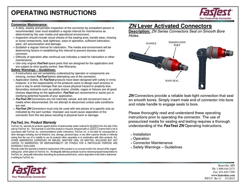
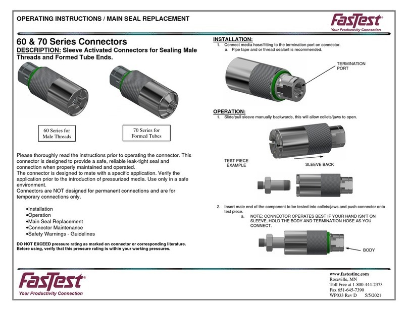
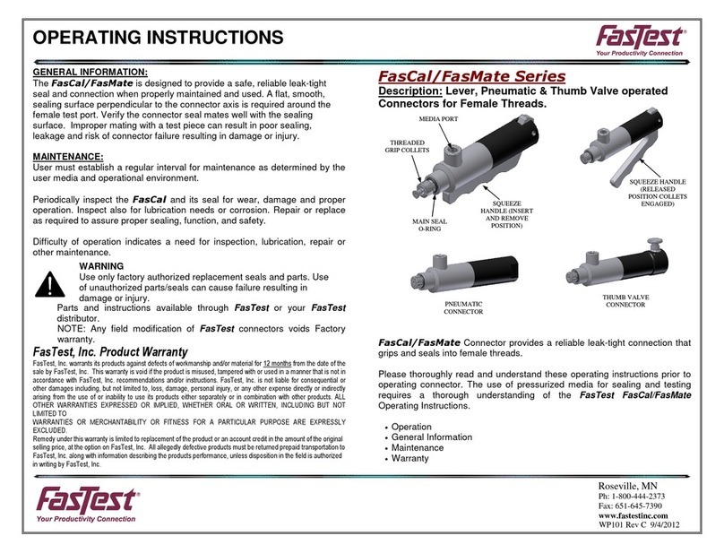
60/70 Series Connectors with ICON™
Description: 60/70 Series Connectors to Grip and Seal Male
threads and Males Features with ICON™ CV04.
60/70 ICON™ Connectors provide a reliable leak-tight
connection that grips and seals male threads and male features.
Please thoroughly read and understand these operating
instructions prior to operating the connector. The use of
pressurized media for sealing and testing requires a thorough
understanding of the FasTest 60/70 Operating Instructions.
•ICON™ Analog and SSR Calibration
•Installation
•Mechcanical Operation
•Main Seal Replacement
•Connector Maintenance
•Safety Warnings – Guidelines
GTEK AUTOMATION 26212 Dimension Drive, Suite 150 Lake Forest, CA 92630 Ph. 949-680-4242 www.gtek-automation.com
OPERATING INSTRUCTIONS/MAIN SEAL REPLACEMENT
Page 2 of 4
Roseville, MN
Ph: 1-800-444-2373
Fax: 651-645-7390
www.fastestinc.com
WP168 Rev A 04/25/2021
Analog and SSR Calibration Wiring Diagrams:
CV04SSR PINOUT CV04SSR Wiring Diagram
CV04ANA PINOUT CV04ANA Wiring Diagram
SSR MODULE CALIBRATION, SLEEVE AND PISTON TRAVEL:
Sure Seal™ enabled connectors need to be calibrated to each application. The 60/70
connector retains stored limit(s) even when power is removed. Due to the fine
sensor resolution and variations in seal height, limits may need to be set each time
seals are replaced or the connector is re-built.
In order to calibrate the 60/70, the upper and lower limits will be calibrated by minimum
and maximum piston positions “with sleeve forward”.
70 Series SSR Calibration:
DO NOT CONNECT MEDIA TO TERMINATION PORT ON CONNECTOR
UNTIL CALIBRATION PROCESS IS DONE.
1. Single Point Calibration
a. Connect Sure Seal™ cable to the M8 Termination
b. Connect test piece and ensure connection is good
c. Enter calibration mode
d. Assert calibration signal until led begins flashing
e. Release calibration signal
f. Allow calibration mode to time out
g. Remove test piece from connector
2. Double Point Calibration
a. Connect Sure Seal™ cable to the M8 Termination
b. Enter calibration mode
c. Connect lower limit test piece
d. Assert calibration signal until LED begins flashing
e. Release calibration signal
f. Remove lower limit test piece
g. Insert upper limit test piece
h. Assert calibration signal until LED begins flashing
i. Release calibration signal
j. Remove upper limit test piece
Pinout/Standard M8 Cables
Pin Number
Wire Color
Description
1
BROWN
24 DC
2
WHITE
CALIBRATION
3
BLUE
GROUND
4
BLACK
NC
5
GREY
SSR CONTROL A
6
PINK
SSR CONTROL B
Pinout/Standard M8 Cables
Pin Number
Wire Color
Description
1
BROWN
24 DC
2
WHITE
LED GREEN
3
BLUE
GROUND
4
BLACK
ANALOG OUTPUT
5
GREY
LED RED
6
PINK
LED RETURN
GTEK AUTOMATION 26212 Dimension Drive, Suite 150 Lake Forest, CA 92630 Ph. 949-680-4242 www.gtek-automation.com
OPERATING INSTRUCTIONS/MAIN SEAL REPLACEMENT
Page 3 of 4
Roseville, MN
Ph: 1-800-444-2373
Fax: 651-645-7390
www.fastestinc.com
WP168 Rev A 04/25/2021
60 Series SSR Calibration:
DO NOT CONNECT MEDIA SUPPLY TO TERMINATION PORT ON
CONNECTOR UNTIL CALIBRATION PROCESS IS DONE.
1. Single Point Calibration
a. Single point calibration is not recommended for 60 series
connectors
2. Double Point Calibration
a. Connect Sure Seal™ cable to M8 Termination
b. Connect test piece, then unscrew test piece until piston is not
touching test piece
c. Screw in test piece just until a good seal is made
d. Enter calibration mode
e. Assert calibration signal until LED begins flashing
f. Release calibration signal
g. Remove test piece
ANALOG CALIBRATION, SLEEVE AND PISTON TRAVEL:
60 and 70 Series Analog:
1. Calibration is done in the installation by the intergrator, not on the connector.
Installation:
1. Connect supply line to the termination port.
2. Maximum termination pressure is marked on connector or literature.
3. Connect Sure Seal™ cable to the M8 Termination.
TERMINATION
PORT
M8 PLUG
GTEK AUTOMATION 26212 Dimension Drive, Suite 150 Lake Forest, CA 92630 Ph. 949-680-4242 www.gtek-automation.com
OPERATING INSTRUCTIONS/MAIN SEAL REPLACEMENT
Page 4 of 4
Roseville, MN
Ph: 1-800-444-2373
Fax: 651-645-7390
www.fastestinc.com
WP168 Rev A 04/25/2021
Mechanical Operation:
Connecting Action:
1. Slide the sleeve back or towards the red housing.
2. Collets and or Jaws will open up.
3. Push connector onto test piece. Collets/Jaws will
connect/collapse onto fitting/tube type test piece.
4. Sleeve will spring forward and cover the
collets/jaws.
5. Activate test pressure into termination port.
6. Maximum rated test pressure is marked on
connector.
7. Run test.
Disconnecting Action:
1. Relieve test pressure.
2. Pull sleeve back and dis-connect from test piece.
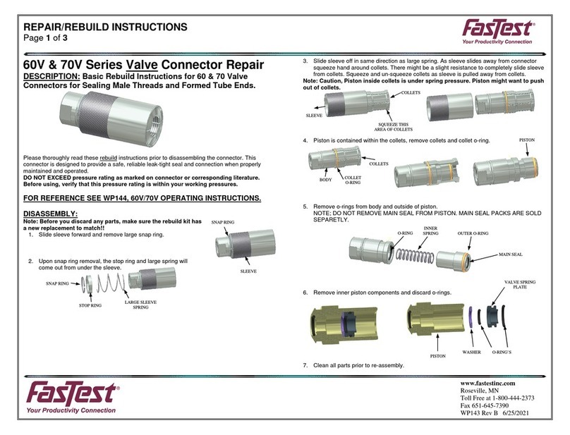
MAIN SEAL REPLACEMENT:
1. In most cases the main seal can be extracted without dis-assembling the
connector.
2. Slide sleeve back, jaws/collets will open.
3. Piston will come forward.
4. Using a pick like tool, extract main seal from piston. (BE AS CAREFUL AS
POSSIBLE NOT TO SCRATCH THE GROOVE SURFACES WHERE SEAL IS
RETAINED!!)
5. Remove and discard.
6. Install new seal into groove on piston. DO NO LUBRICATE THE NEW MAIN
SEAL!
SLEEVE
GTEK AUTOMATION 26212 Dimension Drive, Suite 150 Lake Forest, CA 92630 Ph. 949-680-4242 www.gtek-automation.com


This manual suits for next models

1

Other FasTest Cables And Connectors manuals

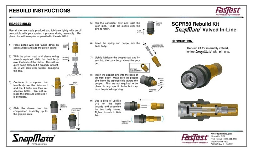
FasTest FasMate Series User manual

FasTest

FasTest FasMate Series User manual

FasTest SnapMate SCPR50 User manual

FasTest

FasTest SnapMate SCPR50 User manual

FasTest ZN Series User manual

FasTest

FasTest ZN Series User manual

FasTest 60V Series User manual

FasTest

FasTest 60V Series User manual

FasTest FI Series User manual

FasTest

FasTest FI Series User manual

FasTest TWISTMATE Series User manual

FasTest

FasTest TWISTMATE Series User manual

FasTest 60V Series User manual

FasTest

FasTest 60V Series User manual

FasTest ICON 60 User manual

FasTest

FasTest ICON 60 User manual

FasTest FN Series User manual

FasTest

FasTest FN Series User manual

FasTest FasCal Series User manual

FasTest

FasTest FasCal Series User manual

FasTest FasMate Series User manual

FasTest

FasTest FasMate Series User manual

FasTest FE001 Series Guide

FasTest

FasTest FE001 Series Guide

FasTest 60 Series User manual

FasTest

FasTest 60 Series User manual

FasTest FI Series User manual

FasTest

FasTest FI Series User manual

Popular Cables And Connectors manuals by other brands

Thermon Terminator ZS Installation procedures

Thermon

Thermon Terminator ZS Installation procedures

ATEN VS0108HB user manual

ATEN

ATEN VS0108HB user manual

Gefen HDTV-142N user manual

Gefen

Gefen HDTV-142N user manual

Philips SWV4156W Specifications

Philips

Philips SWV4156W Specifications

Philips SWV4112W Specifications

Philips

Philips SWV4112W Specifications

PEHA 940 AK Bus Installation and operating instructions

PEHA

PEHA 940 AK Bus Installation and operating instructions

Altrad BELLE MINIPAVE Operator's manual

Altrad

Altrad BELLE MINIPAVE Operator's manual

ABB ACS250 user guide

ABB

ABB ACS250 user guide

ALPHA WORKS GUR052 Operator's manual

ALPHA WORKS

ALPHA WORKS GUR052 Operator's manual

Philips SWV3435S/10 user manual

Philips

Philips SWV3435S/10 user manual

Aus Electronics Direct AA6087 user manual

Aus Electronics Direct

Aus Electronics Direct AA6087 user manual

Delphi 15336034 Assembly manual

Delphi

Delphi 15336034 Assembly manual

LEISUREWIZE LW670 instruction manual

LEISUREWIZE

LEISUREWIZE LW670 instruction manual

Heimeier Vekotec Installation and operating instructions

Heimeier

Heimeier Vekotec Installation and operating instructions

Oasis N-CNG P30 Installation and operating manual

Oasis

Oasis N-CNG P30 Installation and operating manual

Philips SWA3568 Specifications

Philips

Philips SWA3568 Specifications

Philips SWV3434W Specifications

Philips

Philips SWV3434W Specifications

NEUTRIK powerCON TRUE1 TOP Assembly instruction

NEUTRIK

NEUTRIK powerCON TRUE1 TOP Assembly instruction

manuals.online logo
manuals.online logoBrands
  • About & Mission
  • Contact us
  • Privacy Policy
  • Terms and Conditions

Copyright 2025 Manuals.Online. All Rights Reserved.