manuals.online logo
Brands
  1. Home
  2. •
  3. Brands
  4. •
  5. Zamel
  6. •
  7. Temperature Controllers
  8. •
  9. Zamel RTS-02 User manual

Zamel RTS-02 User manual

MATEC – ELECTRIC HEATING SYSTEMS
TEMPERATURE CONTROLLER RTS-02
MANUAL INSTRUCTION
ZAMEL Sp. z o.o.
ul. Zielona 27, 43-200 Pszczyna, Poland
tel. +48 32 449 15 00, +48 32 210 46 65, fax +48 (32) 210 80 04
www.zamel.com, e-mail: [email protected]
OPERATION AND FUNCTIONALITY
6) A demand to display oor temperature.
In the operation mode where a room temperature sensor and a oor temperature limiter are used (position 8 of the conguration menu), pressing and hold-
ing the  button for 3 seconds causes current oor temperature displayes. In case the sensor is not mounted or is damaged - Er symbol will be displayed.
7) Current day and time adjustment.
● Momentary pressing of the button causes the hour pulsates.
● Choose proper hour and AM / PM symbol by pressing and holding ▲ and ▼ buttons (AM shows time since midnight, AM shows time since noon).
● After choosing the hour press again the button. Minutes should pulsate.
● Choose proper minutes by pressing and holding ▲ and ▼ buttons.
● After choosing the minutes press again the button. The days of the week should pulsate.
● Choose a proper day by pressing and holding ▲ and ▼ buttons. Press once button. The display should show proper time and day. if no button is pressed
within 20 seconds the regulator switches to the operation mode according to the adjusted programme
8) Programme planning.
It is recommended to see the default settings of Times and temperatures in an exemplary schedule. If the programme is suitable press button  so the regula-
tor starts operation according to the default settings. To change the adjusted times and temperatures follow the below description. Specify demanded times
and temperatures. Four time intervals must be programmed per one day. Temperature and starting time of the heating phase can be chosen independently.
(For example, following settings can be chosen: 05:00 AM and 21°C for the beginning of the rst heating time-interval for a workday, and also 07:00 AM and
16,5°C for the rst cooling time interval). It is recommended to write all time intervals and temperatures for all intervals in a table. A complete table enables
to save the user’s programme.
Heating schedule (programme default setting):
Time interval Days of the week (5 days) Saturday Sunday
Start time Temperature Start time Temperature Start time Temperature
Heating
6:00 AM 21 °C 6:00 AM 21 °C 6:00 AM 21 °C
8:00 AM 16,5 °C 8:00 AM 16,5 °C 8:00 AM 16,5 °C
5:00 PM 21 °C 5:00 PM 21 °C 5:00 PM 21 °C
10:00 PM 16,5 °C 10:00 PM 16,5 °C 10:00 PM 16,5 °C
9) Heating programme introduction
1. Press once button .„PRGM SETTING” command displays. Pulsating symbols of weekdays „Mon Tue Wed Thu Fri” will be shown on a display with
currently programmed start times for the rst heating time interval. The temperature for this interval will also be shown. The icon signals about
programming of the rst time interval (Get up).
2. Press button  to adjust programmed time and temperature. Press button  once (programmed temperature value will be displayed in a pulsating way).
Press ▲ and ▼ buttons to change the displayed temperature for the rst heating time interval.
3. Press button  once (programmed time value will be displayed in a pulsating way). Press ▲ and ▼ buttons to adjust the demanded time. Time displayed
changes in a 15 minutes way. Press TIME button again after demanded time was chosen to return to the temperature change mode.
4. Press button once. The icon for the second time interval programming is displayed (Go out). The display also shows currently adjusted start time
and temperature for the second heating time interval.
5. Repeat steps 2 and 3 to adjust parameters for the second time interval of the programme.
6. Repeat steps from 2 to 5 for the third and fourth time intervals of the programme.
7. Press button  once. „SA” symbol is displayed (programming for Saturday). The display also shows currently adjusted start time and temperature for
the rst heating time interval.
8. Repeat steps from 2 to 7 to insert programme data for Saturday.
9. Press button  once to adjust Sunday („SU”) and repeat steps from 2 to 7 to insert programme data for Sunday.
10. Press button  after inserting all data for the heating programme.
10) Return to the default settings.
Press button  to enter the programming mode. Press simultaneously ▲ and ▼ buttons for 3 seconds. „DEF” symbol is displayed three times (it pulsates),
the programme returns to the setting phase. Press button  so the regulator can start operation according to the default setting. In case no button is pressed
within 20 seconds the regulator returns to the operation mode compatible with the adjusted programme.
11) Control of the adjusted programme.
In order to check the adjusted programme settings before the programme starts, it is recommended to follow the below description. Press button to to
check the rst time interval data for a working day. Pressing button  every time makes times and temperatures are displayed for the following time interval
(sequentially) for working days, and next for Saturday and Sunday (every time and temperature can be changed while reviewing). Press button so the
regulator can start operation according to the adjusted programme.
WARRANTY CARD
There is 24 months guarantee on the product
Salesman stamp and signature, date of sale
1. ZAMEL Sp. z o.o. assures 24 months guarantee for the product.
2. The manufacturer’s guarantee does not cover any of the following actions:
a) mechanical damage during transport, loading / unloading or under other circumstances,
b) damage caused by incorrect product mounting or misuse,
c) damage caused by unauthorised modications made by the PURCHASER or any third parties to the product or any other devices
needed for the product functioning,
d) damage caused by Act of God or any other incidents independent of the manufacturer - ZAMEL Sp z o.o.
e) power supply (batteries) to be equipped with a device in the moment of sale (if they appear);
3. The PURCHASER shall lay any claims in writing to the dealer or ZAMEL Sp. z o.o.
4. ZAMEL Sp. z o.o. is liable for processing any claim according to current Polish legislation.
5. ZAMEL Sp. z o.o. shall process the claim at its own discretion: product repair, replacement or money return.
6. The manufacturer’s guarantee is valid in the Republic of Poland.
7. The PURCHASER’s statutory rights in any applicable legislation whether against the retailer arising from the purchase contract or
otherwise are not affected by this warranty.
APPEARANCE
The device is designed for single-phase
installation and must be installed in ac-
cordance with standards valid in a par-
ticular country. The device should be
connected according to the details included in this
operating manual. Installation, connection and con-
trol should be carried out by a qualied electrician
staff, who act in accordance with the service manual
and the device functions.
In case of casing dismantling an electric shock may
occur, and the guarantee is lost then. Before instal-
lation make sure the connection cables are not un-
der voltage. The cruciform head screwdriver 2,5 mm
should be used to instal the device. Improper trans-
port, storage, and use of the device inuence its
wrong functioning. It is not advisable to instal the
device in the following cases: if any device part is
missing or the device is damaged or deformed. In
case of improper functioning of the device contact
the producer.
The symbol means selective
collecting of electrical and electronic
equipment. It is forbidden to put
the used equipment together with
other waste.
CAUTION!
FEATURES
TECHNICAL DATADESCRIPTION
• a big LCD display;
• the LCD display shows simultaneously the
adjusted temperature and the room tem-
perature;
• user’s settings and default settings are kept
in a non-volatile memory;
• temperature is displayed in: Celsius or
Fahrenheit (temperature) scales;
• 3 control modes - MODE A: - control by
means of a room sensor, MODE F: - con-
trol by means of a floor sensor, MODE AF:
- control by means of a room sensor with
floor temperature limitation;
• separate programming possibility for 5
weekdays and for a cycle of 1 day / 1 day
(Saturday/Sunday);
• programming with four separate time inter-
vals / temperature intervals during a day;
• calibration possibility of a displayed tem-
perature value;
• protection against freezing;
• pump protection.
RTS-02 temperature controller is a pro-
grammable regulator. It is used to heat oors
and to limit oor’s temperature. The device
cooperates with electric and water oor heat-
ing systems. RTS-02 is equipped with battery
supply backup (2 x AA battery).
RTS-02
Input (supply) terminals: L, N
Input rated voltage: 100 ÷ 240 V~
Nominal frequency: 50 / 60 Hz
Nominal power consumption: 0,40 W – STANDBY
Battery backup: Yes (2 x AA battery)
NTC senor terminals: RT2+, RT2-
Temperature sensor: NTC 100k dla 25 °C
Room temperature adjustment range: +5 ÷ +50 °C
Floor temperature control range: +5 ÷ +50 °C
Accuracy of temperature measurement: ±1 °C
Adjustment accuracy: ±0,5 °C
Output type: relay 16A dla 250 VAC
Number of terminal clamps: 7
Section of connecting cables: 0,5 ÷ 1,5 mm2
Ambient temperature range: -5 ÷ +50 °C
Casing mounting: surface
Casing protection degree: IP21
Protection level: II
Overvoltage category: II
Dimensions: 90 x 115 x 29 mm (height x width x depth)
Weight: 0,180 kg
Reference standard: ETSI EN301 489-1, ETSI EN301 489-3,
EN 60730-1:2000+A12:2003,
EN 60730-2-9:2002
1. Power supply button (Switch on / Switch off).
2 A bi-functional button to display the room temperature,
the oor temperature and time adjustments.
3 Default settings button.
4 Programme start conrmation button.
5 Reset button.
6 Maximum temperature adjustment button.
7 Minimum temperature adjustment button.
8. Current day or programmed days display. 9. Cur-
rent time or programmed time display. 10. Am: time in-
dication: morning and afternoon, Pm: time indication:
afternoon and evening, Days: number of days, Hours:
number of hours. 11. Temperature scales display: Cel-
sius (°C) or Fahrenheit (°F). 12. Temperature adjust-
ment range. 13. Temperature limit excess in AF mode
signalling.14. Regulator’s programming mode signal-
ling. 15. Pump protection mode signalling. 16. 16-A:
Signalling of the mode operation with a room tempera-
ture sensor, 16-F: Signalling of the mode operation
with a oor temperature sensor, 16-AF: Signalling of
the mode operation with a room temperature sensor
and a oor temperature limiter. 17. Heating switch
on signalling. 18. Standby symbol. 19. Time ranges:
the remaining time to wake up , the remaining time to leave , the remaining time to return , the remaining
time to go and rest . 20. Day / time adjustment: current time and day display. 21. Prog setting: Signalling of the
programme setting adjustment mode. 22. Cofg: Signalling of regulator’s conguration mode. 23. Signalling of the cur-
rent regulator’s operation mode. 24. Signalling of the holiday temperature mode. 25. Current room temperature display.
8 9 10 11 12
1617
15
14
13
23
24
25
1819202122
plik: inst_cet_en_rts-02 | modykacja: 20.04.2017
REGULATOR’S MOUNTING PLACE
CONTROLLER’S OPERATION MODES
TEMPERATURE REGULATOR MOUNTING
● The regulator should be installed in a heated room - flat surface mounting,
● Mounting height: about 120 cm from the heated floor surface,
● The regulator should be mounted in a place without a direct sunlight and strong draughts,
● Temperature in mounting places should not exceed values given in technical parameters T = -5 °C ÷ +50 °C,
● Mounting of RTS-02 temperature regulator is shown in the attached diagram.
CAUTON: In case the oor sensor was not mounted or was damaged during mounting phase, the regulator switches off the
output that controls heating in AF MODE.
The regulator can operate in three modes, which can be chosen by pressing 8 of the conguration menu.
MODE A: a regulation mode by means of a room temperature sensor;
In this mode an (internal) air sensor of the regulator is used.
The device switches on and switches off the oor heating or another heating system based on a comparison of the demanded temperature and the room
temperature. Heating should start immediately when the demanded temperature is 1 °C higher than the room temperature in the fast heating mode or 3 °C
higher than the room temperature in the slow heating mode.
MODE F: a regulation mode by means of a oor temperature sensor; This mode is used in case there is no inner oor sensor and there is no possibility
of its mounting.
Application
Preserving the same oor temperature in bathrooms and rooms where a warm surface is demanded. In this mode there is an external oor sensor control.
The heating is switched on and switched off on the basis of a comparison of the demanded temperature with the current oor temperature. The heating should
start when the demanded temperature is 1 °C higher than the oor temperature in the fast heating mode or 3 °C higher than the oor temperature in the slow
heating mode.
Caution:
In case the oor sensor was not mounted or was damaged during mounting phase, the regulator blocks the output that controls heating in F MODE.
Er symbol will be displayed in the oor temperature place.
MODE AF: a regulation mode by means of a room sensor and a oor temperature limiter; AF mode is a normal operating mode in oor heating systems.
Floor sensor cable should be connected to RT2+ and RT2- terminals on a terminal strip. In case the oor sensor is not mounted, a pulsating symbol Alarm
will be displayed and the regulator blocks the output that controls heating. Er symbol will be displayed in the oor temperature place.
In AF mode the regulator switches on and switches off the heating on the basis of a comparison of the room temperature, the demanded temperature and
the adjusted oor temperature limit with a current oor temperature. Minimum and maximum oor temperature limit is adjusted by choosing positions 3 or 4
in the conguration menu. If the oor temperature is between the upper and the bottom temperature limit, heating should start immediately if the demanded
temperature is 1 °C higher than the current room temperature in the fast heating mode or 3 °C higher than the current room temperature in the slow heating
mode. In case the oor temperature exceeds the adjusted upper limit the heating will be switched off and a pulsating symbol Alarm will be displayed. In case
the oor temperature lowers below the adjusted bottom limit the heating should switch on and a pulsating symbol Alarm will be displayed. If the oor tem-
perature exceeds the upper adjusted limit - Hi symbol will be displayed; if the oor temperature will be below the bottom limit - Lo symbol will be displayed.
A pulsating symbol Alarm will also be displayed.
1. Undo 2 mounting screws from the regulator’s base. Carefully separate the
control panel from the base. Pressing or levering the regulator can dama-
ge the regulator’s module.
2. Floor sensor cable should be connected to RT2+ and RT2- terminals on a
terminal strip (see gure). In case the oor sensor was not mounted or was
damaged during mounting phase, the regulator switches off the output that
controls heating in AF MODE, and when the oor temperature command
is chosen - Er symbol is displayed.
3. Connect power supply and load cables with the terminals left on the ter-
minal strips which is placed on the regulator’s base (gure). Place the
supplying base to the wall.
4. Mount the base to the wall by means of two mounting screws. (Levelling
guarantees only the good look of the mounted device and do not inuence
proper working of the regulator).
5. Place the control panel back in the base. Mount the control panel to the
base by means of two screws described in point 1.
RT2-, RT2+: oor sensor terminals
N, L: power supply terminals
T1, T2: load terminals
Figure - terminal block description of the RTS-02 regulator RT2- N T1 T2 LRT2+
Wall mounting screws
Mounting screws
Control panel
Base
Heating mat
Regulator
FUNCTIONING
OPERATION AND FUNCTIONALITY
Conguration menu
Conguration menu enables the adjustment of some heating system values and user demand values. In order to enter the conguration menu switch the
temepature controller into position OFF (protection against freezing) by pressing  button, and next holding button for 3 seconds.
The rst position of the conguration menu appears on the display. Press  button to enter the next menu position. Change the position value by means of
▲ and ▼ buttons. Press  button to escape from the conguration menu. Press the  button to enter the operation mode according to the adjusted pro-
gramme. If no button is pressed within 20 seconds the menu is automatically closed. In order to return to the default settings enter the conguration menu
to press and hold for 3 seconds ▲ and ▼ buttons simultaneously. „DEF” command appears three times on the display, and position 1 of the menu will be
displayed to indicate that all conguration settings are default.
Conguration menu table shows all conguration options:
Pos Pressed
button
Displayed command
(default settings)
Choice range by means of
▲ and ▼ buttons
Description
101 (0) -3 --- +3 Increasing or lowering the displayed temperature value
202 (35 °C) 18 ÷ 35 °C Choosing the maximum room temperature setting
303 (5 °C) 5 ÷ 20 °C Choosing the minimum oor alarm temperature
404 (40) 20 ÷ 40 °C Choosing the maximum oor alarm temperature
505 ( °C) °C / °F Choosing Celsius or Fahrenheit (temperature) scales
606 (FA) FA / SL Choosing fast heating mode (FA) or slow heating mode (SL)
707 (OO) PP / OO Choosing pump protection function (PP). Switching off pump protection function (OO).
808 (AF) AF / F / A Choosing the operation mode: A: Regulation mode by means of a room temperature sensor.
F: Regulation mode by means of a oor sensor. AF: Regulation mode by means of a room
sensor and a oor temperature limiter.
909 (1) 1, 2, 3 Choosing the LCD backlight.
10 Press  button to return to the operation mode according to the adjusted programme.
Explanation of particular options:
1) Recalibration of the displayed temperature in the range of -3 to +3 degrees. The displayed room temperature value can be changed to 3 degrees above
or below indications compatible with default settings for temperature measurement. The regulator was precisely calibrated, but there is a possibility to change the
displayed value in order to adjust it, for example, to values of the previously used device by a user. The room temperature, current temperature or the adjusted tem-
perature will be shown in the right part of the LCD display.
2) Choosing the maximum room temperature setting. This position enables to adjust the maximum room temperature. 35°C is the default setting. The adjustment
can be changed in the range of 18 to 35°C by means of ▲ and ▼ buttons.
3) Choosing the minimum oor alarm temperature. Use ▲ and ▼ buttons to choose a demanded minimum limit temperature. The temperature can be changed
in the range of 5 to 20 °C. 5°C is the default setting.
4) Choosing the maximum oor alarm temperature. Use ▲ and ▼ buttons to choose a demanded maximum limit temperature. The temperature can be changed
in the range of 20 to 40 °C. 40°C is the default setting.
5) Choosing Celsius or Fahrenheit (temperature) scales. The temperature scale can be chosen either in Celsius or in Fahrenheit. Celsius is the default setting.
6) Choosing fast heating mode (FA) or slow heating mode (SL). FA mode: - the heating is switched on when the adjusted temperature is 1 °C higher than the
room temperature. SL mode: - the heating is switched on when the adjusted temperature is 3 °C higher than the room temperature.
7) Choosing pump protection function (PP). In case of water installation systems it is recommended to switch on the pump for at least 15 seconds every 24 hours,
it will protect the pump against seizing. Choose the PP position to activate the pump protection mode. Choose the OO position to switch off the pump protection
mode. OO, 15 symbol is displayed during the pump protection mode is activated. OO is the default setting.
8) Choosing the temperature regulation mode. The regulator can operate in three modes: A, F and AF (AF is the default setting). A: Regulation mode by means
of a room temperature sensor. F: Regulation mode by means of a oor sensor. AF: Regulation mode by means of a room sensor and a oor temperature limiter.
9) Choosing the LCD backlight.The backlight improves the contrast of the LCD display in poor light conditions. 1 is the default setting. 1 - the backlight is switched
on by pressing any button of the regulator, 2 - backlight is switched off, 3 - he backlight is on continuously.
1) Activation of the anti-freezing mode (anti-freezing) / switching off the device.
In a sufciently warm climate, a user can switch off the regulator or activate the anti-freezing mode by pressing  button.Quick pressing of the button ac-
tivates the anti-freezing mode, the display shows the hour, the weekday and the room temperature. 5°C is the default setting of the anti-freezing temperature.
In this mode a temperature fall in a room up to 5°C causes the heating switches on until the temperature reaches 9°C. In cases of installation systems with
hot water by choosing PP option (position 7 in the conguration menu), the device activates the pump for at least 15 seconds once per 24 hours in order to
avoid its seizing. Pressing shortly again the  power supply button causes the anti-freezing mode switches off and a return to the standard operation mode.
Pressing and holding the button for 3 seconds causes the device switches off.
2) Functioning according to the adjusted programme and operation in a mode to preserve the temperature at the same level.
After a momentary pressing of the  button the regulator controls the heating system according to the adjusted programme. „Prog running” command on
the display signals about the regulator’s operation which is compatible with the adjusted programme. Pressing and holding the button for 3 seconds causes
the regulator changes its mode to preserve the temperature at the same level. In this mode the regulator preserves the room temperature according to the
previously adjusted value. „Hold” command on the display informs about regulator’s operation in this mode.
3) Change to a manual operation of the temperature.
Pressing ▲ and ▼ buttons during operation of the adjusted programme enables a user to choose a demanded temperature. The new setting deletes tempera-
ture values chosen for the programme in progress and forces the temperature to be kept at a chosen level until the programme switches to the next phase
(the next time-interval). After the new phase has started the regulator starts operation according to the adjusted programme.
4) Preserving the holiday temperature.
Pressing and holding the button for 3 seconds causes vacation command appears on the display. It informs that the regulator changed to the previously
adjusted holiday temperature. By means of  button the number of the days (from 1 to 99) can be increased, and pressing the button can decrease the
number of the days. Pressing ▲ and ▼ buttons choose required holiday temperature. Pressing the  button enables to return to the operation of the adjusted
programme.
5) Device reset.
If the information on the display is shown incorrectly, gently press the reset button. Reset with the help of an object with a thin tip, for example, a straightened
paper clip. This will reset the regulator’s settings.

Other Zamel Temperature Controllers manuals

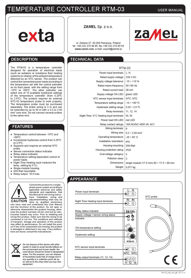
Zamel exta RTM-03 User manual

Zamel

Zamel exta RTM-03 User manual

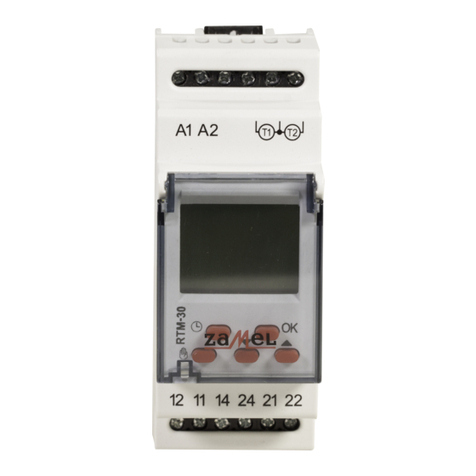
Zamel RTM-30 User manual

Zamel

Zamel RTM-30 User manual

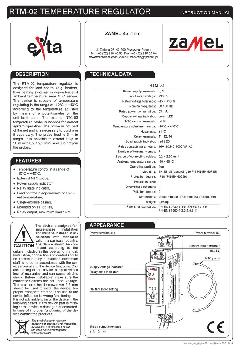
Zamel exta RTM-02 User manual

Zamel

Zamel exta RTM-02 User manual

Popular Temperature Controllers manuals by other brands

AUTOMATION24 TC6704 operating instructions

AUTOMATION24

AUTOMATION24 TC6704 operating instructions

THORLABS TED200C Operation manual

THORLABS

THORLABS TED200C Operation manual

Siemens RVL470 Basic documentation

Siemens

Siemens RVL470 Basic documentation

SMC Networks Thermo-con INR-244-639 Operation manual

SMC Networks

SMC Networks Thermo-con INR-244-639 Operation manual

Elsner Cala KNX T 201 Sunblind quick start guide

Elsner

Elsner Cala KNX T 201 Sunblind quick start guide

Honeywell TS33F user manual

Honeywell

Honeywell TS33F user manual

HeatWave Labs 101303-50 user manual

HeatWave Labs

HeatWave Labs 101303-50 user manual

APAR AR247 series operating instructions

APAR

APAR AR247 series operating instructions

Venta AirSense ECO operating instructions

Venta

Venta AirSense ECO operating instructions

Danfoss C17 Installer's guide

Danfoss

Danfoss C17 Installer's guide

Gira G1 installation instructions

Gira

Gira G1 installation instructions

LCN LCN-GTS6 installation guide

LCN

LCN LCN-GTS6 installation guide

Viessmann Vitotrol 100 UTDB-RF2 Installation and service instructions

Viessmann

Viessmann Vitotrol 100 UTDB-RF2 Installation and service instructions

Adeunis RF sigfox TEMP user guide

Adeunis RF

Adeunis RF sigfox TEMP user guide

Nestbox B1BBH user guide

Nestbox

Nestbox B1BBH user guide

YOKOGAWA UT130 user manual

YOKOGAWA

YOKOGAWA UT130 user manual

VOLTCRAFT ECB-1000P operating instructions

VOLTCRAFT

VOLTCRAFT ECB-1000P operating instructions

Minco CT425 Technical user guide

Minco

Minco CT425 Technical user guide

manuals.online logo
manuals.online logoBrands
  • About & Mission
  • Contact us
  • Privacy Policy
  • Terms and Conditions

Copyright 2025 Manuals.Online. All Rights Reserved.