manuals.online logo
Brands
  1. Home
  2. •
  3. Brands
  4. •
  5. Zamel
  6. •
  7. Temperature Controllers
  8. •
  9. Zamel exta RTM-03 User manual

Zamel exta RTM-03 User manual

TEMPERATURE CONTROLLER RTM-03 USER MANUAL
rtm-03_instr_ext_gb | 29.11.21
APPEARANCE
FEATURES
TECHNICAL DATA
DESCRIPTION
RTM-03
Power input terminals: L, N
Rated supply voltage: 230 V AC
Supply voltage tolerance: -15 ÷ +10 %
Rated mains frequency: 50 / 60 Hz
Rated current load: 26 mA
Supply voltage ON LED: green LED
NTC sensor input terminals: NTC, NTC
Temperature setting range: -10 ÷ +90 ºC
Hysteresis setting range: 0,25 ÷ 2,5 ºC
Relay terminals: 11, 12, 14
Night-Time -5°C Heating input terminals: IN, IN
Power load ON LED: red LED
Relay contact ratings: 16A NO/NC 4000 VA AC1
Wiring terminals: 9
Wiring size: 0,2 ÷ 2,50 mm2
Operating temperature: -20 ÷ 60 oC
Installation orientation: any
Housing mounting: DIN-Rail
Housing protection rating: IP20
Overvoltage category: II
Pollution class: 2
Dimensions: single module (17.5 mm) 90 × 17.5 × 66 mm
Weight: 0,077 kg
● Temperaturecontrolbetween-10ºCand
+90ºC.
● Incrementalhysteresiscontrolfrom0.25ºC
to 2.5ºC.
● SupportsandrequiresanexternalNTC
probe.
● Sensorconnectionstatusindicator.
● Relaystatusindicator.
● Temperaturesetting-dependentcontrolof
power loads.
● Night-TimeHeatinginput(reducesthe
temp. setting by 5°C).
● Single-modulehousing.
● DIN-Railmountable.
● Relayoutput:16Amax.
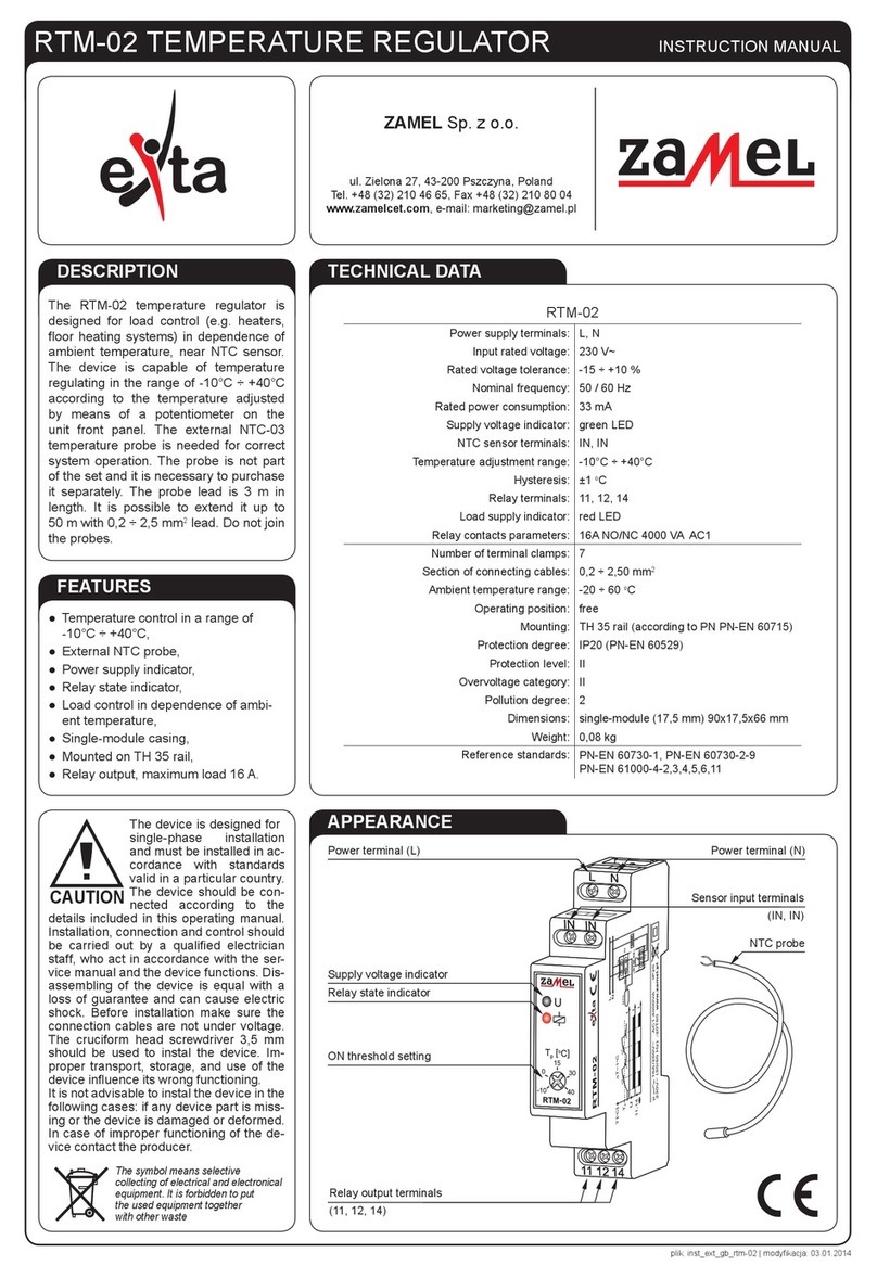
The RTM-03 is a temperature controller
designed for operation of electrical loads
(such as radiators or resistance floor heating
systems) in relation of the ambient temperature
detected by an NTC sensor. The product can
control the connected power loads according to
the temperature set with the control potmeter
on its front panel, with the setting range from
-10ºC to +90ºC. The other potmeter can
select one of 10 available hysteresis settings
of the temperature controller (from 0.25ºC
to 2.5ºC). The product requires an external
NTC-03 temperature probe to work properly.
The temperature probe must be purchased
separately. The probe wiring is 3 m and can
be extended by up to 50 m with a 0.2 to 2.50
mm2core wire. Do not connect several probes
to the same wire.
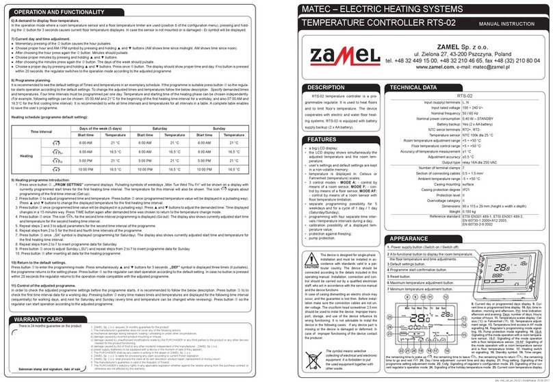
Connect this product to a single-
phase power system according to
applicable electrical and safety
standards and regulations. See
this Manual for the wiring instruc-
tions. Installation, wiring and
adjustment/setting shall only be
done by qualied electricians
who have read and understood this User Manual
and the functions of the product. Do not open or
otherwise disassemble the product housing; other-
wise the product warranty will be void and an elec-
trocution hazard may occur. Prior to installing and
wiring this product, make sure that the wiring to be
connected is not live. The conditions and methods
of transport, storage and operation of this product
may affect its performance. Do not install the prod-
uct if any of its components are missing, the product
is damaged or deformed in any way. If any malfunc-
tions are found, consult the manufacturer.
CAUTION
Relay output terminals (11; 12; 14)
Do not dispose of this device with other
waste! In order to avoid harmful effects on
the environment and human health, the
used device should be stored in designated
areas. For this purpose, you can dispose
of household waste free of charge and in
any quantity to a collection point set up,
as well as to the shop when you buy new
equipment.
ZAMEL Sp. z o.o.
Power input terminals
ON temperature setting
Hysteresis setting
NTC sensor input terminals
Night Time Heating input terminals
Relay status indicator
Supply voltage / sensor wiring status
indicator
NTC probe
ul. Zielona 27, 43-200 Pszczyna, Poland
tel. +48 (32) 210 46 65, fax +48 (32) 210 80 04
www.zamel.com, e-mail: [email protected]
rtm-03_instr_ext_gb | 29.11.21
APPLICATION
INSTALLATION, OPERATION
DIMENSIONS
1. Isolate from power the wiring system to be
connected with this product with its circuit
breaker, overcurrent device or disconnec-
tor, as applicable.
2. Use a suitable tester to verify that the iso-
lated power input wiring is not live.
3. Install the RTM-03 on a DIN-Rail in the re-
spective switchboard.
4. Connect the wiring to the terminals, see
the applicable wiring connection diagram.
5. Turn on the power of the connected wiring
system.
The product is ready for use once properly
installed and wired. The product monitors the
ambient temperature of the external NTC sen-
sor (probe). If the ambient temperature is below
T-∆T,thetemperaturecontrollerswitchesthe
output relay ON (make outputs 11-14), which
powers on the wired power load (e.g. an elec-
tric radiator). The power load will remain on
until the ambient temperature is T+ ∆T. The
temperature hysteresis, which is user-settable
between 0.25°C and 2.5°C, eliminates too fre-
quent switching of the relay within its switching
threshold tolerance. The auxiliary input can be
wired to an external control timer or control
switch for periodic reduction of the ambient
temperature by 5°C (the so-called Night-Time
Heating mode).
NTC sensor wiring indication:
• Wiring shorter / sensor missing: the green
LED pulses 1/second;
• Sensor wiring OK: the green LED stays on.
CONNECTION TIME COURSE
INTERNAL DIAGRAM
Floor heating control system.
Heater
μC
L
N
L
N
PRODUCT FAMILY
The RTM-03 is a model from the RTM
range of temperature controllers.
Product version:
01 - basic
02 - extended
03 - with settable hyster-
esis and Night-Time
Heating input
20 - with LCD panel
30 - with LCD panel ex-
tended
Product type code
∆T (0,25oC ÷ 2,5oC)
T+∆T
T-∆T
T+∆T
T-∆T
WARRANTY CARD
There is 24 months guarantee on the product
Salesman stamp and signature, date of sale
1. ZAMEL provides a two-year warranty for its products.
2. The ZAMEL warranty does not cover:
a) mechanical defects resulting from transport, loading / unloading or other circumstances
b) defects resulting from incorrect installation or operation of ZAMEL products;
c) defects resulting from any changes made by CUSTOMERS or third parties, to products sold or equipment necessary for the correct
operation of products sold;
d) defects resulting from force majeure or other aleatory events for which ZAMEL is not liable;
e) power supply (batteries) to be equipped with a device in the moment of sale (if they appear);
3. All complaints in relation to the warranty must be provided by the CUSTOMER in writing to the retailer after discovering a defect.;
4. ZAMEL will review complaints in accordance with existing regulations.;
5. The way a complaint is settled, e.g. replacement of the product, repair or refund, is left to the discretion of ZAMEL.
6. Guarantee does not exclude, does not limit, nor does it suspend the rights of the PURCHASER resulting from the discrepancy be-
tween the goods and the contract.

Other Zamel Temperature Controllers manuals

Zamel exta RTM-02 User manual

Zamel

Zamel exta RTM-02 User manual

Zamel RTS-02 User manual

Zamel

Zamel RTS-02 User manual

Zamel RTM-30 User manual

Zamel

Zamel RTM-30 User manual

Popular Temperature Controllers manuals by other brands

AUTOMATION24 TC6704 operating instructions

AUTOMATION24

AUTOMATION24 TC6704 operating instructions

THORLABS TED200C Operation manual

THORLABS

THORLABS TED200C Operation manual

Siemens RVL470 Basic documentation

Siemens

Siemens RVL470 Basic documentation

SMC Networks Thermo-con INR-244-639 Operation manual

SMC Networks

SMC Networks Thermo-con INR-244-639 Operation manual

Elsner Cala KNX T 201 Sunblind quick start guide

Elsner

Elsner Cala KNX T 201 Sunblind quick start guide

Honeywell TS33F user manual

Honeywell

Honeywell TS33F user manual

HeatWave Labs 101303-50 user manual

HeatWave Labs

HeatWave Labs 101303-50 user manual

APAR AR247 series operating instructions

APAR

APAR AR247 series operating instructions

Venta AirSense ECO operating instructions

Venta

Venta AirSense ECO operating instructions

Danfoss C17 Installer's guide

Danfoss

Danfoss C17 Installer's guide

Gira G1 installation instructions

Gira

Gira G1 installation instructions

LCN LCN-GTS6 installation guide

LCN

LCN LCN-GTS6 installation guide

Viessmann Vitotrol 100 UTDB-RF2 Installation and service instructions

Viessmann

Viessmann Vitotrol 100 UTDB-RF2 Installation and service instructions

Adeunis RF sigfox TEMP user guide

Adeunis RF

Adeunis RF sigfox TEMP user guide

Nestbox B1BBH user guide

Nestbox

Nestbox B1BBH user guide

YOKOGAWA UT130 user manual

YOKOGAWA

YOKOGAWA UT130 user manual

VOLTCRAFT ECB-1000P operating instructions

VOLTCRAFT

VOLTCRAFT ECB-1000P operating instructions

Minco CT425 Technical user guide

Minco

Minco CT425 Technical user guide

manuals.online logo
manuals.online logoBrands
  • About & Mission
  • Contact us
  • Privacy Policy
  • Terms and Conditions

Copyright 2025 Manuals.Online. All Rights Reserved.