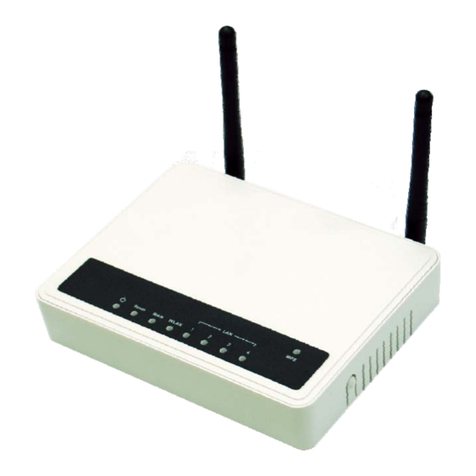
ZComax CPE-250HP Series User manual

CPE
AIRRUNNER
2.4 GHz
Wireless
Network
Station/Router
With Integrated Antenna
CPE-250HP Series
QUICK START GUIDE

Quick Start Guide CPE
2
** IMPORTANT **
Changes or modifications not expressly approved by Zcomax Technologies, Inc. may void the users authority to operate the
equipment.
“Note: This equipment has been tested and found to comply with the limits for a Class A digital device, pursuant
to Part 15 of the FCC Rules. These limits are designed to provide reasonable protection against harmful
interference when the equipment is operated in a commercial environment. This equipment generates uses and
can radiate frequency energy and, if not installed and used in accordance with the instruction manual, may cause
harmful interference to radio communications. Operation of this equipment in a residential area is likely to cause
harmful interference in which case the user will be required to correct the interference at his own expense”.
FCC STATEMENT

Quick-Start Guide CPE
3
READ INSTRUCTIONS
oAll safety and operating instructions should be read
before operating the product.
RETAIN INSTRUCTIONS
oThe safety and operating instructions should be
retained for future reference.
HEED WARNINGS
oAll warnings on the product and in the operating
instructions should be adhered to.
FOLLOW INSTRUCTIONS
oAll operating and use instructions should be followed.
CLEANING
oUnplug this product from the wall outlet before
cleaning. Use only a damp cloth for cleaning.
ATTACHMENTS
oDo not use attachments not recommended by the
product manufacturer as they may cause hazards.
WATER AND MOISTURE
oDo not submerse this product in water. Do not use
the indoor-use only accessories near water.
WALL OR MAST MOUNTING
oThis product should be mounted to a wall or mast
only as recommended by the manufacturer. Do not
stand in front of product during operation.
VENTILATION
oThe product should be situated so that its location or
position does not interfere with its proper ventilation.
POWER SOURCES
oThis product should be operated only from the type
of power source indicated on the marking label.
GROUNDING OR POLARIZATION
oPrecautions should be taken so that the grounding
or polarization means of this product is not defeated.
POWER CORD PROTECTION
oPower supply cord should be routed so that they are
not likely to be walked on or pinched by the items
placed upon or against them, paying particular
attention to cord at plugs, convenience receptacles,
and the point where they exit from the product.
OVERLOADING
oDo not overload wall outlet or extension cords, as
this can result in a risk of fire or electric shock.
OBJECT AND LIQUID ENTRY
oNever push objects of any kind in this product as
they may touch dangerous voltage points or short
out parts that could result in a fire or electric shock.
Never allow liquid of any kind to enter the product.
SERVICING
oDo not attempt to service this product yourself
beyond that described in the operating instructions.
All other servicing should be referred to qualified
service personnel.
HEAT
oThe product should be situated away from heat sources
such as radiators, heat registers, stoves, or other
appliances (including amplifiers) that produce heat.
OUTDOOR ANTENNA GROUNDING
oBe sure the product is grounded so as to provide
some protection against voltage surges and built up
static charges.
oSection 810 of the National Electrical Code (NEC),
ANSI/NFPA No. 70-1990, provides information with
respect to proper grounding of the mast and
supporting structure, grounding of the lead-in wire to
an antenna-discharge unit, size of grounding
conductors, location of antenna-discharge unit,
connection to ground electrodes, and requirements
for the grounding electrode.
oNote to Installer: This reminder is provided to
call the installer’s attention to article 820-40 of
the NEC that provide guidelines for proper
grounding and in particular, specifies that the
cable ground should be connected to the
grounding system of the building, as close to the
point of cable entry as practical.
DAMAGE REQUIRING SERVICE
oThis product should be serviced by qualified service
personnel when:
The power supply cord or plug has been
damaged, or
An object or liquid has entered into the
product, or
The product does not operate normally or
exhibits a marked changed in
performance, or
The product has been dropped, or the
enclosure has been damaged.
This product should only be installed by a
qualified professional.
The unit must only be installed with the antennas
that are approved for use. Following is a list of
approved antenna types:
18dBi Flat Panel
15dBi Flat Panel
Use of higher gain antennas or different style
antennas are forbidden and void the authority to
operate the equipment.
1. Check Product Contents.
Check product for complete contents. The
following items should be included in the box.
a. CPE-250HP Series unit
b. AC Adaptor*
c. Power Injector*
d. 6’ Category-5 Cable*
IMPORTANT SAFETY INSTRUCTIONS
INSTALLATION

Quick Start Guide CPE
4
e. Software CD
f. This Guide
g. Mast-mount Hardware:
i. Brackets x 2
ii. Clamps x 2
iii. Screws x 4
iv. Washers x 8
v. Nuts x 4
* WARNING: Items “b”, “c” and “d” are for indoor-use
only.
2. Prepare For Installation.
The following tools and items are required for
installing the product.
a. A flat-heat screw driver
b. A drill
c. A wall feed-thru tube
d. An antenna mast*
* Note: The product is designed to be mast-
mounted. Alternatively, the product may be
wall mounted (hardware not included).
3. Gather Basic Information.
Gather the following information and write it in
the space provided for future reference. Enter
“NA” for not applicable. Refer to end of this
Guide for sample configurations.
a. Password: __default______________
b. ESSID: _____________________
c. IP Address: _____________________
d. Netmask: _____________________
e. Gateway: _____________________
f. Enable DHCP client: YES ___ NO ___
g. Enable Internal Router: YES ___ NO ___
h. Internal Router’s WAN Port on:
WLAN _____ Ethernet ____
i. NAT: YES _______ NO_________
j. Internal Router’s LAN port IP address:
_______________________
k. Internal Router’s LAN port Netmask:
_______________________
l. Enable Internal DHCP server:
YES ________ NO ________
Begin IP_________________
End IP__________________
Netmask________________
Gateway________________
Primary DNS_____________
Secondary DNS___________
Primary WINS ____________
Secondary WINS _________
m. WEP Key: _______________________
4. Install Software.
Install the software on a PC connected to the
same Ethernet segment as the product.
a. Insert the CD into your CD-ROM drive.
Run SETUP.EXE from the CD's root
directory.
b. Follow the on-screen prompts to install
the software on to your system.
5. Connect All Cables.
Connect cables as follows:
a. Insert the Category-5 cable to the Power
Injector port marked "NETWORK". Insert
the other end of the cable to an Ethernet
hub.
b. Insert the CPE-250HP's RJ-45 connector
to the Power Injector port marked "CPE".
c. Insert the AC adaptor connector to the
Power Injector port marked "DC In". Insert
the AC adaptor to a wall AC outlet. The
Power LED on the CPE-250HP should
turn on.
6. Configure Product.
On a PC that is attached to the same Ethernet
segment as the CPE-250HP, run the installed
CPE-250 Manager software to configure the
product.
a. On the Windows desktop, click on
START|PROGRAMS|ZCOMAX CPE-250
MANAGER/CPE-250 MANAGER to start the
software.
b. Once started, the CPE-250 Manager will
browse the Ethernet segment to locate
any attached CPE-250HP Series
products. It will display all CPE-250HP
units that it can locate during this
discovery process. Each CPE-250HP unit
is displayed in the form of an icon with its
default name listed below. This default
name is formed by concatenating "AP"
with the last 6 numbers of the CPE-
250HP's MAC address (example:
AP123456).
c. Double click on the CPE-250HP product
you wish to configure.
d. Enter “default” at the password prompt.
e. Once logged into the CPE-250HP, the
software will display the main screen.
Click on the tab labeled "CONFIGURATION".
f. The
CONFIGURATION screen is now
displayed. Click on the tab labeled "IEEE
802.11".
g. The
IEEE 802.11 screen is now displayed.

CPE Quick Start Guide
5
h. Enter the ESSID you have gathered from
Step 2. Do not click on the "APPLY"
button now.
i. Click on the tab labeled "IP Address".
j. If you would like to enable the internal
router, select "IP Router" in the TCP/IP
mode selection box and continue to the
next step.
Otherwise choose "Bridge Only" and
perform the following two sub-steps:
i. Enter the IP Address information
from Step 2, or choose to use
DHCP to automatically obtain IP
address, netmask and gateway
information from a DHCP server
by clicking on the "DHCP status"
radio button.
ii. Skip the steps below by
continuing onto Step “v”.
k. Configure the router's WAN port using
information from Step 2 by clicking on one
of the following two radio buttons:
i. WAN on WLA (WLAN)
ii. WAN on Eth (Ethernet)
l. Click on the "SETUP” button just ABOVE
the radio buttons in Step “l” (above) to
setup the WAN port.
m. A new window pops up over the current
window. Click on the "Manual" radio
button to manually configure the WAN
port's IP address, netmask, and gateway.
Or click on the "DHCP" radio button to
automatically assign IP address, netmask,
and gateway information from a DHCP
server.
n. If Network Address Translation (NAT) is
required (i.e., private LAN) place a check
mark next to "NAT (IP Sharing) through
this port".
o. Click on the "Close" button to close this
pop-up window.
p. You are now returned to the original IP
Address tab window. Click on the "SETUP"
button BELOW the WAN port radio
buttons (WAN on WLA, WAN on ETH) to
setup the LAN port.
q. A new windows pops over the current
windows. Enter the Router's LAN port IP
Address and netmask.
r. If you would like to use the built-in DHCP
server to centrally assign IP resources to
PCs on the private LAN, place a check
mark next to "Enable DHCP server".
s. Enter the Start and End IP address for the
DHCP server to assign to DHCP clients
on the private LAN.
t. Enter netmask, gateway, DNS and WINS
server information for the DHCP server to
assign, or click on the radio buttons under
"Use DHCP Wizard" to automatically
obtain this information from the WAN port.
u. Click on the "Close" button to close this
pop-up window.
v. Click on the tab labeled "WEP".
w. The
WEP screen is now displayed.
x. If WEP is required, enter WEP key from
information gathered in Step 2.
y. The product is now fully configured. Click
the "Apply" button. The software will
prompt you that the product will reset to
apply the changes. Click on the "YES"
button to reset the product. Click on the
“LOGOFF” icon to exit the software.
7. Mount Product And Align Internal Antenna.
Warning: As a wireless communication device, the
product has been designed to radiate microwave
(2.4GHz) energy and should only be installed by
qualified professionals. Observe all safety
instructions when performing installation,
specifically, to reduce potential long-term health
hazard, do not stand in front (or within the beam-
width) of the product when it is operating, or position
the product so as to allow exposure of microwave
energy toward human body.
a. Unplug the product from the Power
Injector. Select a suitable outdoor location
to mount the product. Install an antenna
mast as per instruction furnished with
mast and in accordance with National
Electrical Code requirements*
* Note: Be sure the product is grounded so as
to provide some protection against voltage
and built-up static charge. Section 810 of the
National Electrical Code (NEC), ANSI/NFPA
No. 70-1990, provides information with
respect to proper grounding of the mast and
supporting structure, grounding of the lead-in
wire to an antenna-discharge unit, size of
grounding conductors, location of antenna-
discharge unit, connection to ground
electrodes, and requirements for the
grounding electrode.
b. Mount the product by following the
instructions in the section “Using the
Mounting Hardware” (see next section
below). Do not completely tighten the
mounting clamps at this time.
c. Align the product’s internal antenna by
pointing the product directly at the Access

Quick Start Guide CPE
6
Point in which the product is programmed
to associate with.
d. Select a suitable location on an exterior
wall as the cable entry point into the
building. Create an opening at this entry
point using a drill with the proper bit.
e. Insert a wall feed-thru tube into the
opening at the entry point.
f. Route the product’s Ethernet cable into
the building via the wall feed-thru tube*.
*Note: Make sure to create a “drip loop” in the
cable just before it enters the building. Water
easily runs along the slick surface of the
Ethernet cable, and can run right down the
cable and into the building. A drip loop allows
the runoff water to collect and drip off before it
enters the building.
g. Seal the wall feed-thru tube as necessary.
h. Reconnect the product’s RJ-45 connector
into the Power Injector port marked “CPE.
i. The “POWER” LED should turn on. The
“LINK” LED should turn on once the
product associates with an Access Point.
Adjust the product’s position for better
antenna alignment if necessary*. Tighten
the mounting clamps and secure all
cables against the walls as necessary.
*Note: You may optionally fine-tune the
antenna alignment by checking the received
signal strength via the following telnet
command: STAT
8. Change The Default Password.
It is recommended that you change the
default password. To change the password,
run the CPE-250 Manager software and login
with the default password (“default”). Click on
the tab labeled “CONFIGURATION”. Within the
CONFIGURATION screen, click on the tab
labeled “ADMINISTRATION”. Enter the new
password in both “New Password” and
“Confirm Change” text boxes. Click on the
“APPLY” button. The software prompts that
the product will reset for the changes to take
effect. Click on the “YES” button to reset the
product. It is recommended that you confirm
this change by logging in with the new
password.
1. Mount Screws.
Insert one screw from the front of the product
through one of its top mounting holes with a
sealing washer on either side of the mounting
hole. Ensure the seal side of both washers is
against the product. Repeat process for the other
mounting hole near by.
2. Mount Brackets.
Align the screw holes in the mounting bracket with
the screws used in Step 1 so that the bracket
points outward from the product when mounted.
Insert the bracket. Tighten one nut into each screw.
3. Repeat Steps 1 & 2.
Repeat Steps 1 & 2 for the bottom mounting holes.
4. Mount Clamps.
Secure the mounting brackets to mast by using
the mounting clamps. Adjust the mounting clamps
using a flat-head screwdriver so that the product
stays in position yet allows for movements for
alignment adjustment. Tighten the clamps only
after the antenna has been aligned.
The CPE device MUST be installed to provide
a separation distance of at least 35cm from
all persons and must not be collocated or
operating in conjunction with any other
transmitter or antenna
The product can be managed via any one of the
following three methods. Refer to the Users Manual
for complete details.
CPE-250 Manager: Run the CPE-250 Manager
Software. Default password: default.
Web-based Management: Point your browser at
the Product’s IP address (default IP address:
192.168.1.1; Default password: default).
Telnet: Open a Telnet session at the product’s IP
address (default IP address: 192.168.1.1; Default
password: default).
Station/Router Configuration (multiple users)
Below is a sample configuration for Wireless ISPs
to deliver wireless broadband access with to
remote (customer) site. The product is installed at
the customer site as a Station with DHCP client
turn on. Its internal router is turned on and NAT is
MANAGING THE CPE
USING THE MOUNTING HARDWARE
SAMPLE CONFIGURATIONS

CPE Quick Start Guide
7
enabled to service a private Ethernet LAN at the
customer site. Within the product, the DHCP
server is enabled to centrally assign IP resources
to PCs on the private LAN. No WEP.
a. Password: __default_______________
b. ESSID: __ABC________________
c. IP Address: ______NA______________
d. Netmask: ______NA______________
e. Gateway: ______NA______________
f. Enable DHCP client: YES _X_ NO ___
g. Enable Internal Router: YES _X_ NO ___
h. Internal Router’s WAN Port on:
WLAN _X__ Ethernet _____
i. NAT: YES ___X___ NO_________
j. Internal Router’s LAN port IP address:
___192.168.1.1___________
k. Internal Router’s LAN port Netmask:
___255.255.255.0__________
l. Enable Internal DHCP server:
YES ___X____ NO _______
Begin IP__192.168.1.10_____
End IP__192.168.1.200______
Netmask__Use DHCP Wizard__
Gateway__Use DHCP Wizard _
Primary DNS_Use DHCP Wizard
Secondary DNS_ UseDHCPWizard
Primary WINS _UseDHCP Wizard
Secondary WINSUseDHCPWizard
m. WEP Key: _______NA_____________
Station Configuration (one user)
Below is a sample configuration for the product as
used in a “one PC only” application. The product
is installed at the customer site as a Station with
DHCP client turn on so that the product will
receive IP resources (address, netmask, etc.)
from an upstream DHCP server. Its internal router
is turned off. No WEP. The product should be
connected directly to a PC using
a. Password: __default_______________
b. ESSID: __ABC________________
c. IP Address: __NA_________________
d. Netmask: __NA_________________
e. Gateway: __NA_________________
f. Enable DHCP client: YES _X_ NO ___
g. Enable Internal Router: YES ___ NO _X
h. Internal Router’s WAN Port on:
WLAN __NA_ Ethernet _ NA
i. NAT: YES __ NA___ NO__ NA___
j. Internal Router’s LAN port IP address:
________ NA____________
k. Internal Router’s LAN port Netmask:
________ NA____________
l. Enable Internal DHCP server:
YES ___NA__ NO ___NA__
Begin IP______NA________
End IP_______NA_________
Netmask______NA________
Gateway______NA________
Primary DNS___NA_______
Secondary DNS_NA_______
Primary WINS ____NA_____
Secondary WINS __NA_____
m. WEP Key: _______NA_____________

Quick Start Guide CPE
8
Copyright 2002 Zcomax Technologies, Inc. All rights reserved.
P/N: QSG15-130. Rev 1.3
Zcomax and AirRunner are registered trademarks
All other registered marks are the property of their respective owners
Table of contents
Other ZComax Network Router manuals