Zenair CH2000 User manual

CH2000 TRAINER
with LYCOMING 0-235-N2C
SERVICE MANUAL
ZENAIR Ltd.
Huronia Airport
Midland, Ontario
Canada L4R 4K8
(705) 526-2871
November 2002

ZENAIR CH2000 SERVICE MANUAL
_______________________________________________________________________
TABLE OF CONTENTS
SECTION I INTRODUCTION SECTION VI POWERPLANT
SECTION II HANDLING AND SERVICING SECTION VII SURFACE CONTROLS
SECTION III INSPECTION SECTION VIII FUEL SYSTEM
SECTION IIIA AIRWORTHINESS LIMITATIONS SECTION IX INSTRUMENTS
SECTION IV STRUCTURE SECTION X ELECTRIC SYSTEM
SECTION V LANDING GEAR AND BRAKES SECTION XI HEATER /VENTILATION
SECTION XII CABIN DOORS
LIST OF EFFECTIVE PAGES
Section
Page
Date
Section
Page
Date
Section
Page
Date
0
0.1
May 2011
5
5.1
Nov-02
9
9.8
Apr 95
0
0.2
May 2011
5
5.2
Nov-02
9
9.9
Apr 95
1
1.1
Nov-02
5
5.3
Nov-02
9
9.10
Apr 95
1
1.2
Apr 96
5
5.4
Apr 95
9
9.11
Apr 95
1
1.3
Apr 95
5
5.5
Nov-02
9
9.12
Apr 95
2
2.1
Apr 95
5
5.6
Nov-02
9
9.13
Apr 95
2
2.2
Oct-00
6
6.1
Feb-00
10
10.1
Apr 95
2
2.3
Nov-02
6
6.2
Nov-02
10
10.2
Oct-00
2
2.4
Nov-02
6
6.3
Apr 96
10
10.3
Oct-00
2
2.5
Oct-00
6
6.4
Feb-00
10
10.4
Apr 96
2
2.6
Feb-00
6
6.5
Feb-00
10
10.5
Sep 95
2
2.7
Apr 96
7
7.1
Feb-00
10
10.6
Apr 95
2
2.8
Feb-00
7
7.2
Nov-02
10
10.7
Apr 95
2
2.9
Feb-00
7
7.3
Nov-02
10
10.8
Oct-00
3
3A
1 Sep 95
7
7.4
Feb-00
11
11.1
Nov-02
3
3.1
May 2011
7
7.5
Feb-00
11
11.2
Nov-02
3
3.2
May 2011
7
7.6
Oct-00
12
12-1
Nov-02
3
3.3
Nov-02
7
7.7
Nov-02
3
3.4
Nov-02
8
8.1
Feb-00
3
3.5
Nov-02
8
8.2
Apr 95
3
3.6
Nov-02
8
8.3
Nov-02
3
3.7
May 2011
8
8.4
Apr 96
3
3.8
Nov-02
8
8.5
Apr 96
3
3.9
Nov-02
9
9.1
Apr 95
3
3.10
Nov-02
9
9.2
Oct-00
4
4.1
Nov-02
9
9.3
Jul 95
4
4.2
Apr 95
9
9.4
Apr 96
4
4.3
Nov-02
9
9.5
Apr 95
4
4.4
Oct-00
9
9.6
Nov-02
4
4.5
Oct-00
9
9.7
Apr 95
May 2011 0.1

ZENAIR CH2000 SERVICE MANUAL
_______________________________________________________________________
SERVICE MANUAL UPDATE LOG
REV. NO.
DATE ISSUED
DATE
INCORPORATED
INSERTED BY
9
May 2011
May 2011
Note: 0.1 and 0.2 with Update sheet(s) are replaced for each new update.
0.2 May-2011

ZENAIR CH2000 SERVICE MANUAL
________________________________________________________________________
SECTION 1
INTRODUCTION
GENERAL
This manual contains service and maintenance instructions for the Zenair CH2000,
designed and manufactured as a versatile two-seat aircraft in the personal and training
aviation field.
SCOPE OF MANUAL
Sections II and III comprise the service part of this manual, whereas Sections IV through
XI comprise the maintenance instructions. The service instructions include ground
handling, servicing, and inspection periods. The maintenance instructions for each system
include troubleshooting, removal and installation of components, and corrective
maintenance and testing; each major system of the aircraft is covered in a separate section.
Only qualified personnel should perform the operations described in this manual.
In the text, reference is made to the following publications:
- General: Owner’s Manual or Aircraft Flight Manual CH2000 - ZENAIR
Parts Catalogue CH2000 - ZENAIR
- Engine: Operator’s Manual and overhaul manual Series O-235 engines - Textron Lycoming
- Propeller: Prop. Logbook (instructions for use and care) - Sensenich Prop. Co.
AC-43.13.1B Aircraft Inspection, Repair and Alteration
is a useful handbook published by the FAA.
“Aircraft Powerplants”, published by McGraw-Hill
(ISBN #0-07-035569-X) is the standard reference for the mechanic
working on the engine.
The description of the aircraft included in this section is limited to general information;
however, the figure gives specific external dimensions.
Nov-02 1.1

ZENAIR CH2000 SERVICE MANUAL
________________________________________________________________________
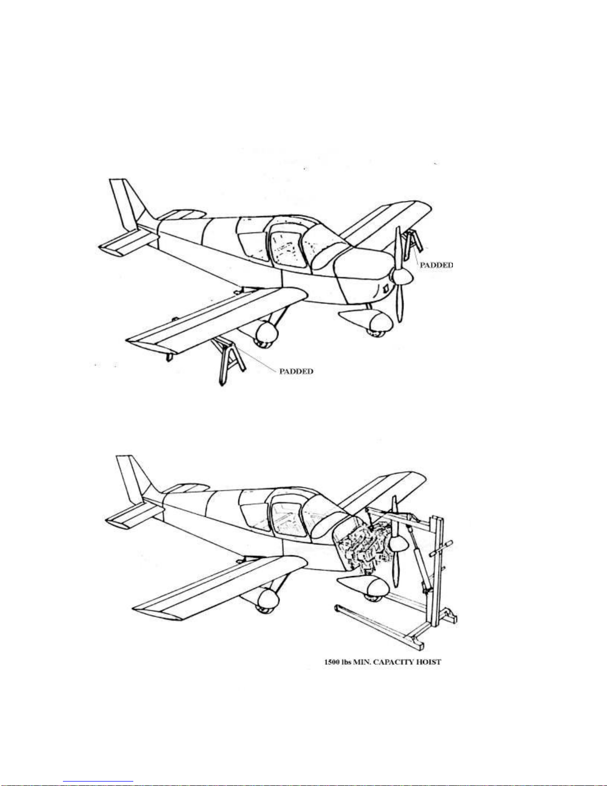
DESCRIPTION - Fig. 1
The Zenair CH2000 is a single engine, two-seat, low-wing monoplane of all-metal
construction.
WING: The wing is of all-metal stressed-skin, full cantilever, low-wing design, consisting
of two wing panels bolted to a spar box assembly in the fuselage. The ailerons are cable
and push rod controlled. The wing trailing edge split flaps are electrically operated.
EMPENNAGE: The empennage consists of the rudder, stabilator, and stabilator trim tabs.
The stabilator is dynamically balanced.
FUSELAGE: The fuselage consists of three basic sections: the engine section, the cabin
section, and the sheet-metal tail cone.
LANDING GEAR: The tricycle landing gear is of the fixed type, consisting of a nose
wheel and two main wheels.
HYDRAULIC SYSTEMS: The dual brake system is operated by master cylinders.
ENGINE: The aircraft is powered by one horizontally opposed Lycoming Model 0-235-
N2C four-cylinder air-cooled engine. The engine employs a wet sump oil system with oil
temperature and pressure indicators.
PROPELLER: The propeller used is a Sensenich fixed pitch, all metal, aluminum alloy,
Model 72-CK series.
FUEL SYSTEM: The fuel system on the Zenair CH2000 consists of one rear aluminum
tank or tanks in the wings, one engine-driven pump, and one electrical auxiliary pump.
FLIGHT CONTROLS: The flight controls are conventional equipment, consisting of a
control wheel which operates the ailerons and stabilator, and pedals which operate the
rudder. Duplicate controls are provided for the co-pilot.
RADIO: Provisions for radio installations consist of microphone and headset jacks and
mounting brackets, necessary wiring, and panel space for extra radios.
CABIN HEATER, DEFROSTER, AND FRESH AIR SYSTEM: Heated air for the cabin
and defroster is obtained directly from the exhaust system muffler shroud. Fresh air is
supplied to the cabin through two individual and orientable air inlet vents in the right and
left door window.
INSTRUMENTS: Provisions for optional instruments are provided, including full IFR
equipment.
1.2 3 Apr 96

ZENAIR CH2000 SERVICE MANUAL
________________________________________________________________________
CH 2000 GENERAL DIMENSIONS
- Fig. 1 -
3 Apr 95 1.3

ZENAIR CH2000 SERVICE MANUAL
________________________________________________________________________
SECTION II
HANDLING AND SERVICING
GENERAL
This section provides ground handling and servicing instructions.
Recommended ground handling procedures, and recommended methods of servicing
are provided in following paragraphs. If trouble or damage to the aircraft is discovered
during ground handling or servicing, refer to the appropriate section for the system
concerned. Lubrication is treated as a separate function.
ACCESS PROVISIONS - Fig. 2
The figure shows the location and identity of the access doors and panels that provide
access for purposes of service and maintenance.
GROUND HANDLING
GENERAL. The aircraft must not be pushed, pulled, or lifted by any other means than
those described. Procedures are given for the proper execution of all necessary handling
operations and, if the instructions are followed, damage to the aircraft or its equipment
will be prevented.
Caution: Use the utmost care at all times during ground handling operations.
STEP, HANDHOLD, AND WALKWAYS
A fixed step is located on each side, below and aft of the inboard end of the wing trailing
edge and fixed handholds are located on the sides of the fuselage, above the aft upper
corner of the rear window. The walkway is made up of a non-skid compound applied to
the wing surface.
Caution: Walk on the walkways only, to avoid damage to the wings.
3 Apr 95 2.1

ZENAIR CH2000 SERVICE MANUAL
________________________________________________________________________
CH2000 ACCESS PANELS
- Fig. 2 -
2.2 Oct-00

ZENAIR CH 2000 SERVICE MANUAL
________________________________________________________________________
HOISTING - Fig. 3
Nose Gear Hoisting - Remove the cowl and lift the aircraft with a hoist attached to the
metal loop on top of the engine.
Main Gear Hoisting - Lift the aircraft one side at a time and insert a padded sawhorse or
equivalent under wing at main wing spar and rib rivet line.
LEVELING - Fig. 4
The aircraft may be leveled while the wheels are on the ground or during the weighing
procedure while the wheels are on scales. Leveling the aircraft for purposes of reweighing
or rigging is accomplished as follows:
Position the level on the door sill (upper fuselage longeron)
To put the airplane in a longitudinally level position, either on scales or on the
floor, deflate the nose wheel tire until the proper position is reached (or add
shims under the two main wheels ).
To level the airplane laterally, place a level across the cabin on the right and
left longerons, shim one main wheel as required. (repeat longitudinal leveling).
WEIGHING PROCEDURE - See Owner's Manual or Aircraft Flight Manual Chapter 6
TIEING DOWN
Secure tie-down ropes to the wing tie-down rings and the tail skid at approximately 45
angles to the ground. Leave sufficient slack to avoid damage to the aircraft when the
ropes contract due to moisture.
TOWING
Move the aircraft using the nose wheel optional tow bar hooked into the nose gear strut
rings.
Caution: Remove the tow bar when not in use as the propeller may hit it when engine is
started.
Nov-02 2.3

ZENAIR CH2000 SERVICE MANUAL
________________________________________________________________________
LOCKING AIRCRAFT
The cabin doors are provided with key locks on the outside.
MAIN GEAR / WHEEL HOISTING
NOSE GEAR / WHEEL HOISTING
2.4 Nov 02

ZENAIR CH2000 SERVICE MANUAL
________________________________________________________________________
AIRCRAFT LEVELING
-Fig. 4 –
Oct-00 2.5

ZENAIR CH2000 SERVICE MANUAL
________________________________________________________________________
SERVICING
FUEL SYSTEM
FILLING FUEL TANKS
Observe all required precautions for handling gasoline. Fill the fuel tanks with the fuel
specified in the engine Operator’s Manual.
DRAINING FUEL VALVE AND STRAINER - Fig. 5
The Gascolator is located under the fuselage near the left wing leading edge. It has a
Curtis type easy drain valve and can be opened to clean the fuel filter. Note: fuel shut-off
valve should be in the "OFF" position when opening the Gascolator.
The Gascolator should be drained regularly to check for water.
REAR FUEL TANK SYSTEM
The fuel tank and sump are drained through the Curtis valve beside the Gascolator.
The fuel strainer at the tank outlet is accessed for removal and cleaning through the large
access door under the fuselage. (see page 7-9 of Owner’s Manual or AFM)
WING TANKS OPTION
The fuel tanks and sumps are drained through the Curtis valves under the wings just rear
of the wheels.
The fuel strainers at the tank outlets are accessed for removal and cleaning through the
access panels beside the Curtis valves. (see next page F.5. Also page 9.6 of Owner’s
Manual or AFM)
2.6 Feb-00

ZENAIR CH2000 SERVICE MANUAL
________________________________________________________________________
FUEL DRAINS
- Fig. 5 -
3 Apr 96 2.7

ZENAIR CH2000 SERVICE MANUAL
________________________________________________________________________
LUBE OIL SYSTEM
FILLING ENGINE SUMP
Fill the engine sump with the specified lubricating oil. (See Owner’s Manual or Engine
Manual.) Access door on right top cowl.(Fig. 2)
DRAINING ENGINE SUMP
Remove the cowl.
Drain the engine sump by means of the oil drain plugs at the bottom of the oil sump.
BRAKE SYSTEM - Fig. 11 on page 5.6
FILLING BRAKE CYLINDER RESERVOIRS
The brake cylinder reservoirs are an integral part of the master cylinders on pilot side.
They must be checked at every 50-hour inspection and replenished when necessary. No
adjustment of brake clearance is necessary on the brakes.
DRAINING BRAKE SYSTEM
To drain the brake system, disconnect the hydraulic brake lines from the brake assembly
of the main gear, and place the end of each line in a suitable container. Slowly pump the
brakes until fluid ceases to flow. To clean the brake system, flush with denatured alcohol.
LUBRICATION - Fig. 6
See the chart for lubrication instructions regarding the locations, time intervals, and types
of lubricant used. Where light lubricating oil is specified, but unavailable, clean engine oil
is a satisfactory substitute. Avoid excess application of lubricants. Excess lubricant on
exterior surfaces of bearings tends to attract dirt and grit, and may lead to malfunction of
the unit.
2.8 Feb-00

ZENAIR CH2000 SERVICE MANUAL
________________________________________________________________________
LUBRICATION CHART
- Fig. 6 -
Feb-00 2.9

ZENAIR CH2000 SERVICE MANUAL
________________________________________________________________________
SECTION IIIA
AIRWORTHINESS LIMITATIONS
GENERAL
This Airworthiness Limitation section is accepted by the FAA. It can only be revised with
prior FAA approval.
LIFE LIMITED PARTS
Following is the list of the parts which must be replaced at the frequencies indicated.
- Fuel line hoses rear of firewall (5 years or 2400 hours, whichever occurs first.)
- Brake lines (7 years)
- Pitot static lines (7 years)
- Electric Trim actuator (2400 hours)
3A. 1 Sep 95

ZENAIR CH2000 SERVICE MANUAL
________________________________________________________________________
SECTION III
INSPECTION
GENERAL
This section provides instructions for conducting scheduled inspections, unscheduled inspections,
replacement of time limited parts and corrosion control. Repair or replacement instructions for those
components found to be unserviceable are in the sections covering the applicable aircraft system.
Refer to Section II for lubrication and servicing instructions. Lubrication and servicing intervals should be
adjusted to take into account the aircraft operating conditions.
Refer to Section IIIA for Airworthiness Limitations.
All of the inspections are general visual inspections unless otherwise specified. They are to be performed by
trained and qualified personnel using appropriate tools and adequate lighting.
Prior to commencing the scheduled inspections listed in Table 1:
a. Thoroughly clean the aircraft and engine;
b. Remove or open the necessary inspection and access panels, the engine cowlings, the spinner and the
optional wheel fairings; and
c. Review the aircraft records for outstanding Airworthiness Directives (AD’s) ,
Airworthiness Limitations (AWLs), Service Bulletins (SBs) or other maintenance requirements (pitot
static system, ELT, fire extinguisher, etc.). Contact the manufacturer for latest AD, SB and Service
Letters.
Note: In addition to the tasks specified in Table 1, do the preflight inspections described in the
Owner’s Manual.
SCHEDULED INSPECTIONS
Scheduled inspections include the items listed in Table 1 Inspection Form, the overhaul
requirements for the engine and propeller, the calendar time inspections and the one-time inspections done
following specified tasks. Do the following:
Inspection Form Requirements
Perform the tasks in Table 1 at the intervals shown. (Refer to Paragraph 6).
Overhaul Requirements
a. Overhaul the engine (Lycoming 0-235) every 2400 flight hours in accordance with Lycoming Direct
Drive Engine Overhaul Manual P/N 602947.
b. Overhaul the propeller (Sensenich Model 72-CK Series) every 2,000 flight hours in accordance with
Sensenich overhaul instructions (Ref. SPRM #590).
c. Overhaul the magnetos every 2,400 flight hours in accordance with the manufacturer’s instructions.
(Ref. Unison Industries - Slick manual # L-1363 sect. 4).
d. Overhaul the horizontal stabilator trim (electric) actuator every 2400 flight hrs. in accordance with the
manufacturer’s overhaul instructions.
Replacement of Time Limited Parts
The following parts are subject to the effects of aging and environmental deterioration and must be
replaced at the time indicated:
Fuel Line Hoses ( rear of firewall) - 5 years or 2400 hours, whichever comes first.
Brake Lines - 7 years
Pitot Static Lines - 7 years
When replacing the fuel lines rear of firewall, replace original fuel lines SAE-30R type with the Parker
SUPER-FLEX FL type.
When replacing the brakes lines and Pitot Static Lines, use Zenair nylon tube type 11 #487-4 or similar with
minimum working preasure of 250 P.S.I. Tube O.D. ¼”, I.D. 0.175 with wall thickness of 0.040. Equivilant
fittings to be used.
May-2011 3.1

ZENAIR CH2000 SERVICE MANUAL
________________________________________________________________________
Calendar Inspection Requirements
a Perform a visual inspection of the pitot-static system connection Tygon splice at the
wing root, for security and condition, every 12 months.
b. Perform a visual inspection of the wing fuel tank compartments (if wing fuel tanks are
installed) for corrosion, cracking, etc every 5 years.
UNSCHEDULED INSPECTIONS
Unscheduled inspections must be performed anytime that unusual operating conditions are
encountered which may affect the integrity or airworthiness of the aircraft. Actions to be taken following the
reporting of such events are as follows:
INSPECTION AFTER SPECIFIED MAINTENANCE ACTIONS
Inspections are to be performed one time only, following the performance of the following tasks:
Installation of new alternator -
drive belt.
Check belt for condition and tension at 25 hours of belt
operation. (Ref. Lycoming Service Instruction #114)
Installation of new, -
re-manufactured or overhauled engine.
Perform a 50-hour engine inspection (Ref. Section 4 of
Lycoming Operator’s Manual).
CORROSION CONTROL
To avoid the deterioration of the CH2000 aircraft due to the effects of corrosion, monitor the
condition of protective coatings on exterior and interior surfaces. If damage to coatings is found, restore
surfaces prior to the occurrence of damage caused by environmental effects.
INSPECTION SCHEDULE
The required inspection tasks and their intervals are listed in Table 1. The tasks are placed in seven
groups: Propeller, Engine, Cabin, Landing Gear, Wing, Fuselage and Empennage.
The first column of Table 1 states the task to be performed, the second column states the applicable
references(s). The third column is divided into four sub-columns, each of which corresponds to an
inspection interval. The last column may be used to verify that a task has been completed. Perform the
stated tasks at the intervals shown when a plus (+) symbol is shown in an interval column. A minus (-)
symbol indicates no maintenance action is required. Tasks may be performed sooner but not later than the
stated intervals. If done sooner, tasks must next be performed at the stated interval (e.g. at 790 flight hours
airframe time, a 100 hour task is performed 10 flight hours before it is due. It must next be performed 100
hours later, at 890 flight hours (or sooner).
Operational checks are tasks that determine that an item is fulfilling its intended purpose. No
verification of meeting tolerances is required.
Functional checks are tasks which determine if one or more functions of an item are performing
within specified limits. Quantitative checks must be performed.
Useful Note: The 50 hour inspection has a tolerance of + 16% (ie between 42 and 58 hours)
May-2011 3.2
Hard Landing
a) Check ELT for inadvertent activation.
b) Check main gear spring for deformation.
c) Check nose gear and firewall for damage.
d) “Inspect per SB Feb 2011 Rev 0”
Propeller Strike
a) Check propeller for damages.
b) Check prop flange re crankshaft damage.
Lightning Strike
a) Check ELT for inadvertent activation.
b) Check skins for damages.
c) Check control connections for damages.
Bird Strike
Check the area for damages
Exceedence of Operational Limits
Refer to applicable manuals

TABLE 1 –ZENAIR INSPECTION FORM
Make / Model
ZENAIR CH2000
Serial No.
Airframe Hours
Type of Inspection
(Circle One)
Registration No:
Engine Hours
50 100 500 1000
Symbols: + Indicates perform task, - Indicates do not perform task
Task
Refer to
Intervals
(Flight Hours)
Initials
50
100
500
1000
Propeller Group
1.Check propeller bolts for torque and
safeties.
2.Inspect blades and hub for cracks,
corrosion, damage, etc.
3.Inspect spinner and backing plate.
Engine Group Danger
Ground magneto primary circuit before
working on engine.
1.Check for oil/fuel leaks.
2.Check for particles on oil suction screen
and sump drain plug.
3.Drain oil and refill.
4.Perform cylinder compression test.
5.Clean the spark plugs. Adjust gap at
.018” to .022”.
6.Check and set magneto timing at 200.
7.Check magneto breaker points and
lubricate breaker point felt.
8.Clean oil suction and oil pressure
screens
9.Inspect the wet type foam air filer.
10. Inspect the exhaust manifold for cracks
(carb and cabin heat shroud removed).
150 HR INTERVALS (Ref. AD-CF-90-
03R2)
11. Inspect the heat shrouds for cracks,
etc.
12. Inspect the motor mount fuselage and
engine attachment points and braces.
13. Inspect the rubber engine vibration
isolating mounts for cracks damage, etc.
Sensenich Prop,
Manual
Sensenich Prop,
Manual
Section X
Lycoming Operator’s
Manual Section 7
Lycoming Operator’s
Manual Section 7
Lycoming Operator’s
Manual Section 5
Lycoming Operator’s
Manual Section 4
Lycoming Operator’s
Manual Section 4
Section VI
Service Letter of
Thursday, June 14,
2001
Section VI
+
+
+
+
+
+
-
-
-
-
+
+
+
-
+
+
+
+
+
+
+
+
+
+
+
+
+
+
+
+
+
+
+
+
+
+
+
+
+
+
+
+
+
+
+
+
+
+
+
+
+
+
+
+
+
+
+
+
+
+
+
+
+
+
3.3 Nov-02

TABLE 1 –ZENAIR INSPECTION FORM
Make / Model
ZENAIR CH2000
Serial No.
Airframe Hours
Type of Inspection
(Circle One)
Registration No:
Engine Hours
50 100 500 1000
Symbols: + Indicates perform task, - Indicates do not perform task
Task
Refer to
Intervals
(Flight Hours)
Initials
50
100
500
1000
14. Inspect engine for security of all
attaching hardware (nuts, bolts, screw,
etc.)
15. Perform valve clearance check
16. Inspect the ignition harnesses for
general condition.
17. Inspect the carburetor air intake box for
leaks.
18. Drain carburetor and clean carburetor
fuel strainer and strainer bowl.
19. Inspect engine cowlings for cracks,
damage, loose rivets, etc.
20. Inspect the vacuum pump, lines and
separator,
21. Change the Oil filter.
22. Inspect the oil radiator, oil lines and
attaching brackets.
23. Clean and flush oil radiator.
24. Inspect engine, firewall and firewall
seals for deterioration, cracking, etc.
25. Inspect cabin heat control box for
cracks, condition, etc.
26. Inspect engine controls for defects,
safeties, etc. Check control travels.
27. Check starter, alternator, fuel pump
and vacuum pump for proper mounting,
security and defects
28. Perform operational checks of all
systems (fuel, oil, heating, etc.)
Lycoming Operator’s
Manual Section 5 and
Lycoming Service
Instruction March 17
1997
Section VI
Section VI
Section VI
Section VI
Section VI
Section XI
Section VI
Section VI
Section VI
-
-
+
+
-
+
-
+
+
-
-
+
-
-
-
+
+
+
+
+
+
+
+
+
-
+
+
+
+
+
+
+
+
+
+
+
+
+
+
+
+
+
+
+
+
+
+
+
+
+
+
+
+
+
+
+
+
+
+
+
3.4 Nov-02
Table of contents
Other Zenair Aircraft manuals
Popular Aircraft manuals by other brands

Diamond Aircraft
Diamond Aircraft DA20-A1 Maintenance manual

Seagull Models
Seagull Models Magic Bird SEA 380 Assembly manual

Shark
Shark UL Flight manual

SOL paragliders
SOL paragliders Flexus LOTUSOne manual

Crosswinds Aviation
Crosswinds Aviation DA20 C1 Eclipse Training manual

Cessna
Cessna 172 1964 Ownersmanual