Zenair STOL CH 701 Technical specifications

Flight Manual
ZENAIR
STOL CH 701
Serial
number:
Regi tration:
Czech Aircraft Works, Czech Republic
edition. 3 CZ
-
March 99

1.
General 2
2.
Limitations
4
3.
Emergency procedures
8
4.
Normal procedures
10
5.
Performance
14
.
Weight and balance/equipment list 1
7.
Aircraft and systems description
19
8.
Aircraft handling, servicing
nrui
maintenance
23
9.
Supplements
27
he structure of document was changed according to requirements of BCAR Section S and
changes due to M OW 450 kg with respect to JAR-VLA rules.

1. General
Introduction
he pilot’s handbook has been prepared to provide pilots and instructors with
information for the safe and efficient operation of this UL-aeroplane.
Certification basis
his type of aircraft has been approved by PFA according to British Civil Airworthiness
Requirements CAP 482 Section S Small Light Aeroplanes, Issue 1 including BCAR Paper
S901
proposed amendments.
Descrip
tive
data
CH 701 is a side-by-side two place, strut-braced high wing monoplane with all-metal
structure. CH 701 is a reliable two seat aircraft designed with pilot and passenger comfort in
mind for short-field capability, excellent performance and good visibility. he S OL CH
701 is truly the aircraft which combines the advantages of a conventional aircraft with those
of an advanced Ultralight.
Standard powerplant is Rotax 912, 4-cylinder, 4-stroke, w/ opposed cylinders
Wing span ................................................................ 8,220 mm
Length ......................................................................
6,100 mm
Height.. ..................................................................... 2,350 mm
MAC
........................................................................
1.43 m
Wing area .................................................................
11.33
m.sq.
Wing loading ............................................................ 39.7 kg/m.sq.
Engine ......................................................................
Rotax
912 80 HP
Propeller.. ................................................................. two or three blade composite or wood
Diameter ...................................................................
1700 mm.

Three-view drawing:
30.7”
(780 mm.)
I
87.5" (2220 mm.) I27FI. 18220mm)

2. Limitations
his section
2
includes operating limitations, instrument markings and basic placards
necessary for safe operation of the aeroplane, its engine, standard system and standard
equipment.
Airspeed
Airspeed limitations and their operational significance are shown below:
VNE
r
VNO
VA
VFE
Speed
Never exceed speed
Maximum structural
cruising speed
Manoeuvring speed
Maximum Flap
extended speed
Airspeed indicator markings:
T
IAS (kt)
94
78
6
55
Remarks
Do not exceed this speed in
any operation
Do not exceed this speed
except in smooth and then
only with caution
Do not make full or abrupt
control movement above this
speed, because under certain
condition the aircraft may be
overstressed by full control
movement
Do not exceed this speed with
flaps extended.
Airspeed indicator markings and their colour-code significance are shown below:
Marking
White arc
IAS value or range (kt)
30
-
55
Green arc
34
-
78
Yellow arc
Red line
Significance
Positive Flap Operating
Range
Normal Operating Range
Manoeuvres must
be
conducted with caution and
only in smooth air
Maximum speed for all
operation
Powerplant:
Engine manufacturer.
...................
.
...............................
Rotax
Engine Model:. ............................................................
Rotas 912
Maximum Power, take-off
.......................................... 80
HP
continuous:
................................................ .77 H P
Maximum Engine RPM, take-off..
..........................
5
800
continuous
........................
5,,
500

Maximum Cylinder Head emperature: . . . . . . . 150 deg.C
Maximum Oil temperature. . . . . . . . . . . . . . . . . . . 140 deg. C
Oil Pressure, Minimum. . . . . . . . . . . . . . . . . . . . .
1.5 bar
Maximum . . . . . . .. . . . . . . . . . . . . 5 bar
Fuel Pressure . . . . . . . . . . . . . . . . . . . . . . . . . . . . 0. 15 - 0.4 bar
Fuel grade.. . . . . . . . . . . . . . . . . . . . . . . . . . . . . . . Premium grade leaded gas, according to
DlN1600, ONORM C1103 EURO
SUPER ROZ 95 unleaded, according to
DIN51603, ONORM C 1101
Oil grade . . . . . . . . . . . . . . . . . . . . . . . . . . . . . . . . . . SAE 20 W 50 or SAE 30 High
performance automotive oil API, S6,
Mobil
1,
15
W50,
NO AVIA ION OIL
Propeller manufacturer
Propeller model
Propeller Blade angle
-
see propeller manual
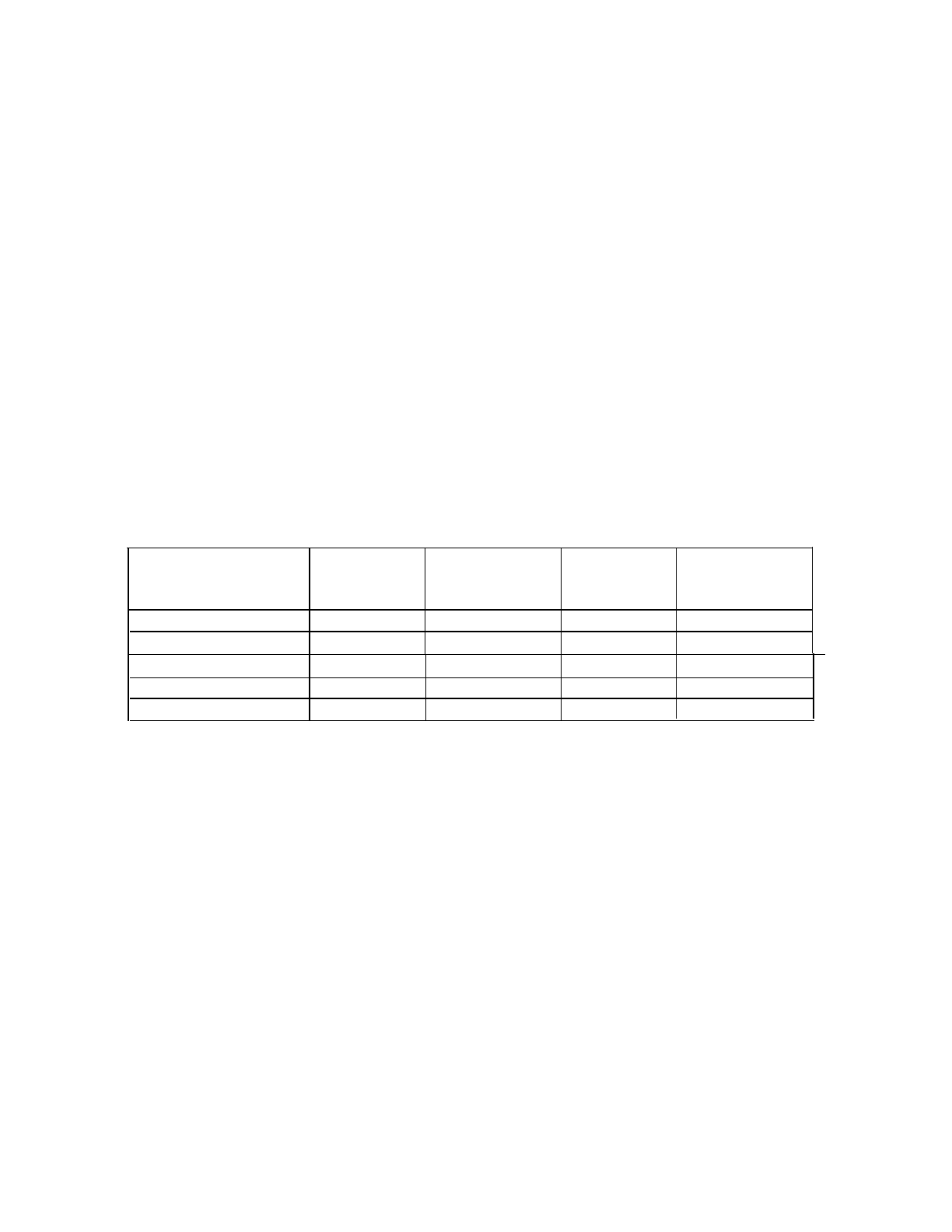
Powerplant instrument markings:
Powerplant instrument markings and their colour code are shown below:
Instrument Red line
Minimum
limit
Green Arc Yellow Arc Red line
Normal operating Caution range Maximum limit
achmeter
500 -5
500 5 500 -
5
800
5 800
Oil emDerature
deg.C 50
90- 110 110-
140
140
Cyl. head temp.
deg.C
150
Fuel (bar)pressure
0.15 0.4
Oil (bar)pressure
1.5
4-5
5
Weight:
Basic Empty weight.....................................................
760
kg.
Maximum take-off weight ..........................................
450 kg
Maximum landing weight.. .........................................
450 kg
Maximum cockpit weight ..........................................
.190
kg
Minimum cockpit weight.. .........................................
.55 kg
Maximum weight in Baggage compartment..
............
.I8 kg
Centre of gravity:
Standard entre of gravity position for empty aircraft is 21.6 % MAC ( 3 10 mm from
reference datum
-
leading edge of slats)
Allowable Range: 20
-
35 % (286 mm to 500 mm)
See section 6 Weight & Balance for details

Approved manoeuvres:
No aerobatics manoeuvres including intentional sppining are approved
Manoeuvring load factors:
Limit load factor: positive 4 negative 2
he ultimate load factors are the limit-load factors multiplied by the safety factor of 1.5
Flight crew:
Minimum number of crew members is 1 and maximum total number of occupants is 2
Kinds of operations:
he aeroplane may be operated in day VFR non-icing condition.
Fuel:
otal capacity:. . . . . . . . . . . . . . . . . . . . . . . . . . . . . . . 42 litres
Usable fuel
:
. . . . . . . . . . . . . . . . . . . . . . . . . . .
1.5 litres
Unusable fuel
:
. . . . . . . . . . . . . . . . . . . . . . . . . . . . . . . 40.5
litres
Approved fuel grades:
. . . . . . . . . . . . . . . . . . . . . . . . . . Premium grade leaded gas, according to
DIN1600,
ONORM Cl 103 EURO
SUPER ROZ 95 unleaded, according to
DlN51603, ONORM C 1101

Limitation placards:
he following limitation placards are placed inside the cockpit:
Never-exceed speed
V
NE
..
.......................................................94 kt
Manoeuvring speed
V
A
..
......................................................... 62
kt
Maximum speed for f aps extended
V
FE
............................55 kt
Maximum Engine RPM,take-off (5 min)
........
5 800
continuous..
.............
5 500
Maximum Cy inder Head Temperature:
.........
150 deg.C
Maximum Oi temperature
.............................
140 deg.C
Maximum oading 18 kg
(40 Ibs)
No oose items
Allowable f el in
litres
baggage weight (kg)
crew weight
(kg) 0 9 18
55 42
42
42
80
42
42 42
100
42
I
42
I
42
140
42
42 42
This aerop ane is c assified as a sma ight
aerop ane approved for day VFR on y, in
non-icing condition. A aerobatics
manoeuvres inc uding intentiona spinning
are prohibited.

3. Emergency proced res
his section provides checklist and amplified procedures for coping with emergencies
that may occur. Emergencies caused by aeroplanes or engine malfunction are extremely
rare if proper preflight inspections and maintenance are practised.
However, should an emergency arise, the basic guidelines described in this section should
be considered and applied to correct the problem.
Emergency landing:
1.
Set airspeed for best rate of Descent 45 kt, flaps up
2. Shut off fuel
3. Shut off engine
4.
ighten seat belts and harness
Avoid tight turns. In some cases, the flaps may be extended before touchdown. Land as usual,
straight ahead power-off approach. Do not try to do any turns
-
the loss of altitude while
gliding is marginal.
Accidental spins:
o recover from a spin:
1.
Pull throttle to idle position
2. push rudder opposite the spin’s rotation
3. bring the pitch control slightly forward.
Fires:
On the ground, before
engine
is started.
1. Go on pushing starter
2. Shut off fuel
3.
Open throttle full as soon as engine starts to blow the fire out
On the ground, engine running.
1. Cabin heat off
2. shut off fuel
3. throttle open to blow fire out
In
the air.
1. Cabin heat off
2. Fuel off
3. Ignition off
4. Electrics off
5.
Perform an emergency landing
Do not attempt to re tart engine after in-flight fire !!!!!!

Fire in cockpit
1. Electrics off
2. Cabin heat off
3. Use fire extinguished
To restart engine in flight (after fuel sfarvafion):
Pull choke before starting and choke in as soon as engine starts.
Note:
Make sure that the aircraft is equipped with a functioning fire extinguisher which is
easily accessible to the pilot. It is recommended to equip the aircraft with an Emergency
Locator ransmitter (EL ) and First Aid Kid.

4. Normal proced res
Section 4 provides checklist and amplified procedures for the conduct of normal
operation.
Obtain adequate professional flight training on the STOL CH 701 and the required pilot
licence before attempting operation of the aircraft.
Pre-flight
inspection:
(“walk around” before each flight):
1.
Ignition switch off, fuel open, controls free.
2. Drain gascolator and all drain valves to ensure that no water is in the fuel lines check
cowl fasteners for looseness, check spinner and prop. You may want to remove the cowl
to check the exhaust and general engine condition for safety. Check fuel quantity as well
as coolant level and water pump.
3. Make a visual check of the front wing attachment points, pitot static, upper forward
strut attachment (remove tie down), condition of slats and wing tip. Folding wings
(option) confirm that the push-pull tubes’ quick release connections are secure.
4. Flaperon, check general condition, hinges, rear strut attachment, flaperon control and rear
wing attachment points
5. Landing gear condition, attachments, tires
6. Stabilator attachments, elevator and rudded hinges, cables and attachments, controls
stops (remove rear tie down).
Continue walk around in reverse order.
2
4
Before
starting engine:
Operate controls and make a rapid visual check for proper operation. Make sure
windshield is clean for maximum visibility. Check brakes, and fasten and check safety belt.

Starting engine:
(Refer also to the engine Manual for detailed information)
1.
fuel valve ON
2.
cock
-
pull (only for cold engine)
3. throttle
-
idle
4. master switch -ON
5. ignition switch ON
6.
turn starter key to start the engine.
When engine start, set RPM to 2 500. Check oil pressure
-
it must raise during 10 sec. after
engine start. Do not increase RPM before oil pressure of 2 bar is reached.
7. Release choke gradually when engine starts.
8.
Avionics and other switches ON
Warm-up and ground test:
(Refer also to the engine Manual for detailed information)
Warm-up the engine until the oil temperature is 50 C. Set RPM to 3850 and proceed with
ignition check Drop must not be greater than 300. he difference between each circuit must
be less than 115. After check of take-off setting let the engine cold.
On cold days, wait for the temperature gauge to register before taxing, allowing the engine
to warm up.
Note: For winter operation, the radiator size may have to be reduced to keep engine
within operating range. Wrap wide tape around the exposed surfaces of the radiator as
required.
Taxing:
With the tricycle configuration taxiing is facilitated by us of a steerable nose wheel. Avoid
steering the aircraft with the brakes. When winds exceed 15 to 20 kt, taxi very slowly to
prevent inadvertent lift-off.
Before take-off:
1.
set altimeter
2. set trim
3.
check avionics and other switches
-
ON
4. flaps up (handle back)
5.
check freedom and deflection of controls
6. check that doors are locked
7.
fasten seat belts, not uncomfortably tight (can you reach fuel shut off valves
?)
8.
check that choke is full in
Take off.-
1.
set throttle
g
raduall
y
to full

2. check RPM and gauges
3. release brakes
4. draw stick slightly back
Note: For short field take-off: same as above but use the middle flaps setting and climb at
the best angle of climb
Note: As you become more familiar with your S OL you can try various flaps settings
and speeds. his may improve short field take-off performances depending on piloting
techniques and skills.
Climb
Best rate of climb
(Vy):
approx. 40 kt, flaps up. his will provide the greatest altitude gain
in shortest time.
Best
angle
of climb
(Vx):
approx. 30 kt, flaps in middle setting (if no middle setting flaps
down). his will provide the greatest altitude gain in the shortest distance.
Make sure that limit values for temperatures and pressures are not exceeded.
Cruise:
75 % cruise is achieved at:
Lower RPM means slower cruise speed, quieter flying, better fuel economy and increased
endurance. Above figured are for standard adjusted propellers.
Descent:
Use some power to prevent engine from cooling too much (approx. 3 000 RPM when
descending at 40 to 50 kt)
Best rate of descent
-
35 kt, flaps up
Approach:
hrottle full back, 35 kt and flaps down (handle forward) will result in a steep approach
for landing in tight spots. Use power to stretch the approach or no flaps
-
extent them only in
short final.
Landing:
When over the runway, move the stick slowly back to prevent touch down until the main
wheels make smooth contact. he nose will drop as soon as the stick pressure is released.

Cross wind landings and wind limitations:
Approach with one wing low, or use crabbing technique, or combination of both.
Straighten the aircraft out just before touchdown. When winds are over 25 kt, simply take-
off and/or land into the wind as practically no ground run is required.
Missed landings:
Apply full power. Pull flaps up when speed is above 40 kt. Continue with circuit pattern
Shut down (engine):
After normal flight and taxing is engine cold enough to turn it off. When long taxing full full
power were made, let the engine cold.
1. switches -OFF
2. ignition switch OFF
3. master switch -OFF
4. fuel valve OFF
Remove ignition key when aircraft is unattended
Note: he hourmeter counts “engine time”
from
the moment the muster switch is turned on.
Do not forget to turn the master switch off.
Tie down:
When the aircraft is not in use, tie it down at each forward strut at wing junction (loop
rope through the hole to prevent it from slipping down and bending the strut) and at the
rear fuselage tie down ring. ie down the stick forward (use a bungee around Y stick
secured at the pedals). Make sure the doors are properly latched. he optional cabin cover
will minimize dust, or damage to the windshield and windows (and keep curious onlookers
out).
Note: As the aircraft is not equipped with a “parking brake” it is important to tie down the
plane when it is not attended.

5. Performance
Section 5 provides data for airspeed calibration, stall speeds and take-off, landing and other
data. he data in the charts has been computed from actual flight tests with the aeroplane and
engine in good condition and using average piloting techniques.
he flight and operational characteristics of the S OL CH 701 are normal in all respects.
here are no “unconventional” characteristics or operations that need to be mastered.
All the controls respond in a usual way within the entire range of operations of the
airplane.
Speeds provided are indicate airspeed
(IAS),
unless specified otherwise.
Pitot must be in correct position
static
-
cabin static pressure
rue airspeed = IAS
+/-
5 kt in normal operations
Performances are given in standard atmosphere. Aircraft and, powerplant in new
condition with standard equipment.
Stall speed (at gross weight 45 kg):
Flaps Up
31 kt
Flaps Down
7
kt
-
the above speeds are with engine at idle, the aircraft simply “mushes in” at stall. he
airplane has a relatively high sink rate with flaps fully lowered.
-
With power, the indicated stall speed is bellow any accurate indication as nose attitude
is very high. Stall occurs around a
walking,
speed preceded
by
substantial buffet. he nose
drops fast.
CAUTION: Maximum flaps extended speed
V
F
= 55
kt
Take-off distances:
in feet, off hard surface, flaps up
Ground roll
Sea level (ISA)
169
3 000
ft densitv altitute
33
000 ft density altitude
ake-off distance
over
15
m obstacle
83
-
take off distances from grass fields are longer and depend on the actual surface.
Landing distances:
Landing distance over 15
m.
obctacle is 283 ft (ground roll 180 ft)

Climb performance chart:
rate of climb (FPM, full throttle):
sea level (ISA)
850
fpm
at IAS
42 kt
3000 ft density alt.
720
fpm
at
IAS 39 kt
6000 ft density alt.
415
fpm
at IAS
35
kt
9000 ft density alt.
200
fpm
at
IAS
33
kt
Service ceiling
with standard original carburetor jet setting: 14 000 feet density altitude at gross weight.
Best rate of climb and best angle of climb
-
see section
4
Fuel consumption:
(Rotax 912)
take-off power . . . . . . . . . . . . . . . . . . . . . . . .
22 litres/hour
75 %
. . . . . . . . . . . . . . . . . . . . . . . . . .16.2 litres/hour
Range and endurance:
engine settings cruise speed (kt)
max. continuous
80
75 % 70
range (NM)
150
180
Above values are valid for aircraft in good condition and are without reserve. Ensure that you
are not exceeding M OW limit 450 kg while loading your aircraft.
Before attempting cross-country flights, proper knowledge of the fuel consumption and
capacity is required.
Best angle of glide
-
(gross weight) 40 kt, with flaps up

6. Weight and balance/eq ipment list
A wide center of gravity range makes loading your Zenair S OL CH 701 easy. Use the
following graph & table and actual weights to calculate and check that marginal points fall
within the permissible range.
hese figures must be within the limits for all flying configurations. Limits for c.g.
position: 20
-
35 % (286 mm to 500 mm).
Weight and center of gravity limits
MTOW 450
kg
110 130 150 170 190
Loaded airplane moment (kg.m)
When c.g of empty aeroplane in standard, the
baggage capacity is not critical for position

Aircraft centre of gravity determination
Measuring the aircraft
-
inflate the tires
-
level the upper fuselage longeron with a spirit level
-
measure the length LF and LR: plumb line on the slat leading edge at rib #l and through the
wheelaxles.
-
weighing the aircraft: Place the empty, but entirely equipped aircraft on 3 scales and
level as above
-
lay the wheel fairings on the appropriate scales.
-
fill weighing report
-
follow the example on the next page.

Sample Weight
&
Balance Report
WN=
75 kg
Scale reading
:
Left main wheel
Right main wheel
Nose wheel
Distances:
Main wheels
Nose wheel
WL
= 92 kg
WR= 91 kg
WN
= 75 kg
LM
= 0.725 m.
LN
= 0.700
m.
XC
= (WL + WR) * LM - LN * WN
=
(92+91) * 0.725 - 75 * 0.7 = 0.311 m.
WL + WR + WN92 + 91 + 75
0.311
% =
___
=
0.217 =
21.7 %
1.43
Sample of the first row of c.g. table:
Actual empty weight
date of weighing.
.
. . . . . . . . . . . . .
Weight Distance Moment
(kg) (m) (kw)
258 0.311
80.2
Date:
Name:
Signature:

7. Aircraft and systems description
his section provides description and operation of the aeroplane and its system.
he S OL CH 701 aircraft design conforms to P 10141 Design Standards for advanced
Ultra-light Aeroplanes (AULA) (Canada) and BCAR Section S (UK).
Construction:
All-metal construction, stressed skin, single curvature metal skins riveted to stiffeners.
Airframe:
Construction is of 6061- 6 aluminium sheet metal riveted to aluminium angles with
Avex rivets. his high strength aluminium alloy construction provides long life and low
maintenance costs thanks to its durability and corrosion resistance characteristics.
Wings:
he wing has a high lift airfoil with full-span fixed leading edge slats (bolted to the wing’s
leading edge) “Junker” type (separate airfoil) full-span
trailing
edge flaperons (combination
flaps
&
ailerons) and Hoerner wing tips to maximize the S OL CH 701’s effective
wingspan.
Flight Contro/s:
he S OL CH 701 is equipped with a dual flight control stick between the pilot and
passenger which branches in the form of a convenient Y handle. he classic rudder pedals,
connected to a large-diameter steerable nose wheel for easy of ground handling, are
equipped with toe-brake hydraulic pedals on the pilot side (on both sides on option) for
effective ground steering. he vertical tail is all moving to provide maximum crosswind
capabilities. he trim-control on the elevator is electrically operated from the switch on
control stck)
he Flap control operates the full span flaperons, it it located on the floor, pilot’s side. o
extend flaps, lift handle and move forward to the provided notch. Maximum permissible
flaps extended speed is 55 kt.
Instrument panel:
Instrument panel is situated in front of pilot and includes instruments for control of the
flight and engine. he aeroplane is fitted al least with those instruments:
Control
of flight
an airspeed indicator
an altimeter
a magnetic direction indicator
slip indicator (ball)
control of
engine
rpm indicator
a fuel quantity indicator
Table of contents
Other Zenair Aircraft manuals
Popular Aircraft manuals by other brands

Diamond Aircraft
Diamond Aircraft DA20-A1 Maintenance manual

Seagull Models
Seagull Models Magic Bird SEA 380 Assembly manual

Shark
Shark UL Flight manual

SOL paragliders
SOL paragliders Flexus LOTUSOne manual

Crosswinds Aviation
Crosswinds Aviation DA20 C1 Eclipse Training manual

Cessna
Cessna 172 1964 Ownersmanual