Zenitel Vingtor Stentofon SPA-V2 Quick guide

TECHNICAL MANUAL A100K10370
Configuration & Installation Manual
Public Address & General Alarm System
SPA-V2
LS zone 1
Cabins
LS zone 2
LS zone 3
LS zone 4
Lifeboat area
PA microphone panel PA microphone & Alarm panel
Alarm panel
Entertainment
LS zone 5
LS zone 6
Engine
area
Open deck
GENERAL
ABANDON
MANUAL
RESET
EMS
SPARE
SPA-A6CD
1
2
3
4
5
6
ALL
SPA-M6D
TALK
DIM.
Open deck
ACM Integrated System
ACM Telephone System
Telephone
PABX
Accommodations
Weatherproof
ZONE1
ZONE2
ZONE3
ZONE4
ZONE5
ZONE6
GENERAL
ALARM
ABANDON
ALARM
MANUAL
ALARM
EMERGENCY
PA
Talk-Back
SPA-V2 Main Unit

2A100K10370
SPA-V2 Public Address & General Alarm System
Installation & Conguration Manual
Contents
1 Introduction...............................................................................................................................4
1.1 About this Document...........................................................................................................4
1.2 Publication Log ...................................................................................................................4
1.3 Related Documents ...........................................................................................................4
1.4 Rules and Regulations........................................................................................................4
2 Installation&CongurationProcedures................................................................................5
2.1 General Description ............................................................................................................5
2.2 Receiving and Inspecting the Equipment............................................................................5
2.3 Planning the Installation......................................................................................................5
2.3.1 Guidance Note......................................................................................................5
2.3.2 Environmental Requirements ...............................................................................6
2.4 Cable Requirements ...........................................................................................................6
2.5 Power Supply Requirements ..............................................................................................7
2.6 InstallationandOutlineSpecications ................................................................................7
2.6.1 Cabinets ...............................................................................................................7
2.6.2 Microphone Panels - Indoors................................................................................9
2.6.3 SPA-M6BOKS.......................................................................................................9
2.6.4 SPA-AC6 & SPA-AC6-D Alarm Panels .................................................................9
2.6.5 ACBOKS.............................................................................................................10
2.6.6 SPA-W1-V2 & SPA-W1-D Weatherproof PA Panels...........................................10
2.6.7 SPA-W1AR-V2 & SPA-W1AR-D......................................................................... 11
2.6.8 SPA-W6A4 & SPA-W6A4-D................................................................................ 11
2.6.9 SPA-REM7..........................................................................................................12
2.6.10 SPA-BOXM1.......................................................................................................12
2.6.11 VM15-RD/VM50-RD & VM15-RDF/VM50-RDF Volume Controls ......................12
2.6.12 STBOKS .............................................................................................................13
2.7 Connecting Equipment......................................................................................................13
2.7.1 Connecting Power Supply 1 ...............................................................................13
2.7.2 Connecting Power Supply 2 ...............................................................................14
2.7.3 Connecting SPA-M1-V2 & SPA-AC6 ..................................................................15
2.7.4 Connecting SPA-M1-D & SPA-AC6-D ................................................................16
2.7.5 Connecting SPA-M6 & SPA-AC6........................................................................17
2.7.6 Connecting SPA-M6-D & SPA-AC6-D ................................................................18
2.7.7 Connecting SPA-W1-V2 .....................................................................................19
2.7.8 Connecting SPA-W1-D .......................................................................................19
2.7.9 Connecting SPA-W1AR-V2 ................................................................................20
2.7.10 Connecting SPA-W1AR-D ..................................................................................21
2.7.11 Connecting SPA-W6A4.......................................................................................22
2.7.12 Connecting SPA-W6A4-D...................................................................................23
2.7.13 Connecting Loudspeaker in Single System........................................................24
2.7.14 Connecting Loudspeaker & Volume Controls in Single Entertainment System..25
2.7.15 Connecting Loudspeaker & Volume Controls in A+B System in Two Racks ......26
2.7.16 Connecting Talk-Back System ............................................................................27
2.7.17 Connecting PABX & Entertainment ....................................................................27
2.7.18 CongurationExample1:Microphonepanels,PABX.........................................28
2.7.19 CongurationExample2:Microphone,AlarmPanels,PABX.............................29
2.7.20 CongurationExample3:DualPA/GA ...............................................................30
2.7.21 CongurationExample4:RequiredPA/GAConnectionbetweenRacks1&2..31
2.8 JumperSettingsforCongurationofFunctions................................................................32
2.8.1 Jumper settings on SPA Terminal Board ............................................................32
2.8.2 Jumper settings on SPA-EMS-V2 board (990-362)............................................33
2.8.3 Volume Control Override ....................................................................................34
2.8.4 Jumper Settings on 4-Way Entertainment 6 Zones Board (990-363).................35
2.8.5 Jumper Settings on SPA Multi 4-Way Entertainment 6 Zones Board (990-338) 35

3
SPA-V2 Public Address & General Alarm System
Installation & Conguration Manual
A100K10370
2.9 Volume Adjustment on SPA Terminal Board .....................................................................36
2.9.1 Signal Adjustment Talk-Back Input .....................................................................36
2.9.2 Signal Adjustment Microphone Input ..................................................................36
2.9.3 Signal Adjustment PABX Input............................................................................36
2.9.4 Signal Adjustment Entertainment Input ..............................................................36
2.9.5 SignalAdjustmentAmplierInput .......................................................................36
2.9.6 VolumeAdjustmentonAmplierVPA-120/VPA-240/VPA-400............................36
2.9.7 VolumeAdjustmentonAmplierEA1400/EA1600 .............................................37
2.10 Loudspeaker Power Consumption....................................................................................37
2.11 Alarm Setup ......................................................................................................................37
2.11.1 Alarms and Priorities ..........................................................................................37
2.11.2 PossibleCongurationofAlarmRelayBoards...................................................37
2.11.3 Frequency Change on Alarm..............................................................................38
2.11.4 Alarm 1 ..............................................................................................................39
2.11.5 Alarm 2 ..............................................................................................................39
2.11.6 Alarm 3 ...............................................................................................................40
2.11.7 Alarm 4 ..............................................................................................................40
2.11.8 Alarm 5 ...............................................................................................................41
2.11.9 Alarm 6 ...............................................................................................................41
2.11.10 Alarm 7 ...............................................................................................................42
2.11.11 Alarm 8 ...............................................................................................................42
2.11.12 Alarm 9 ...............................................................................................................43
2.11.13 Alarm 10 .............................................................................................................43
2.11.14 Alarm 11..............................................................................................................44
2.11.15 Alarm 12 .............................................................................................................44
2.11.16 Alarm 13 .............................................................................................................45
2.11.17 Alarm 14 .............................................................................................................45
2.11.18 Alarm 15 ............................................................................................................46
2.11.19 FIRE Alarm .........................................................................................................46
3 Commissioning.......................................................................................................................47
3.1 General .............................................................................................................................47
3.2 Mechanical Inspection ......................................................................................................47
3.3 Cable Connection Inspection ............................................................................................47
3.4 Power Supply/Consumption Check ..................................................................................47
3.5 FunctionCongurationCheck...........................................................................................47
3.6 Startup Procedure.............................................................................................................48
4 Appendix A: Local Mute.........................................................................................................50
5 AppendixB:CustomAlarmCongurationExample...........................................................51
6 AppendixC:AlarmTonePattern...........................................................................................52
Figures
Figure 1 Available cabinet height options ................................................................................................................. 7
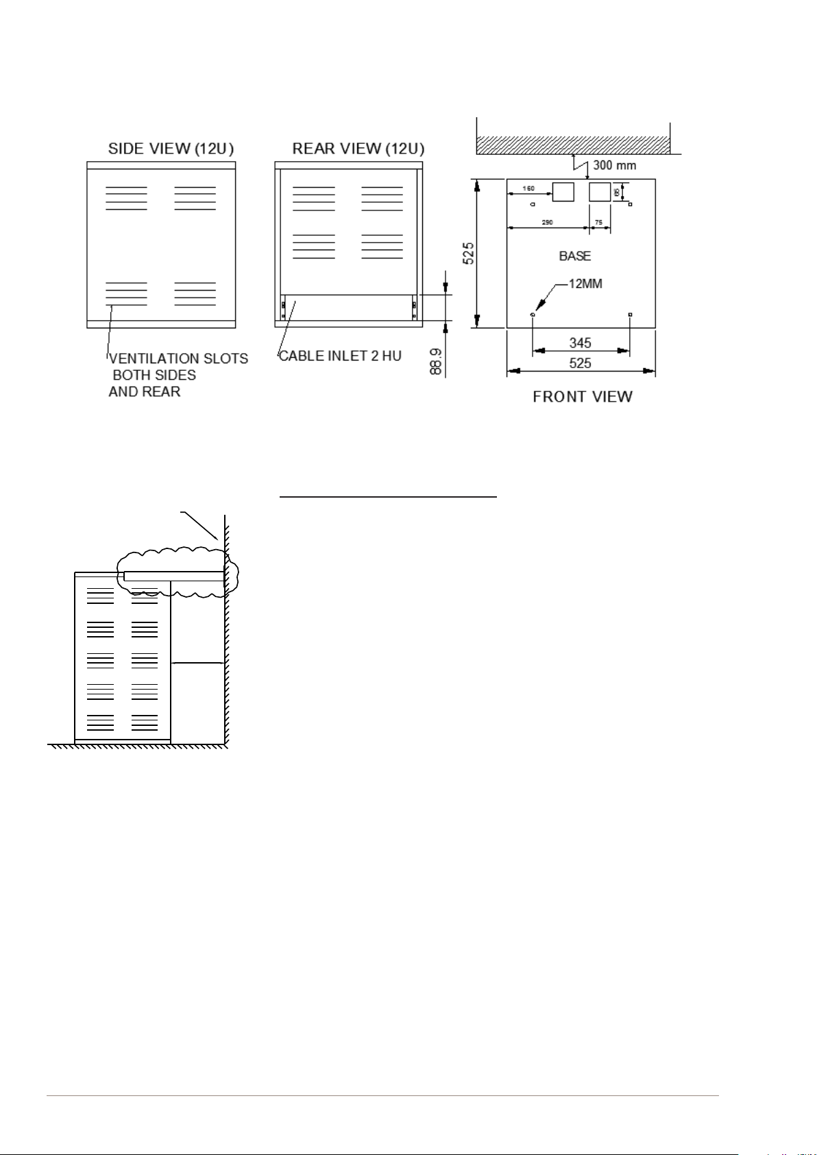
Figure2 Cabinetmeasurementsfront,side&rear................................................................................................... 8
Figure 3 Fastening for 20U and higher racks............................................................................................................ 8
Figure 4 230 VAC and 24 VDC connections........................................................................................................... 13
Figure 5 230/230 VAC with SPA-FAIL board........................................................................................................... 14
Figure6 JumperforEntertainmentOutputtoexternalsystem ............................................................................... 32
Figure 7 Jumper for audio from Talk-Back system.................................................................................................. 32
Figure 8 Jumpers for Alarm Priorities...................................................................................................................... 33
Figure9 Jumpersforexternalaudiooutperzone .................................................................................................. 33
Figure10 Jumpersforrecrewalarmperzone ....................................................................................................... 33
Figure11 JumpersforPBXaudiooutputperzone................................................................................................... 33
Figure 12 Jumpers for Talk-Back with emergency message .................................................................................... 33
Figure13 JumpersforoverrideonAllCallvs.zones1-6 ......................................................................................... 34
Figure 14 Jumpers for override on normal & EMS vs. EMS only.............................................................................. 34
Figure15 Jumpersforoverridewithinternalorexternal24VDC............................................................................. 34
Figure 16 Alarm/Mic Panel with Local Mute for Dual System ................................................................................... 50

4A100K10370
SPA-V2 Public Address & General Alarm System
Installation & Conguration Manual
1 Introduction
1.1 About this Document
The scope of this document is to provide relevant information on the
installation,conguration,andcommissioningoftheSPA-V2Public
Address & General Alarm System for marine vessels.
TheinformationinthisdocumentisaimedatSystemAdministrators,
System Installers and End Users.
1.2 PublicationLog
Rev. Date Author Comments
1.10 2008-3-15 JF Published
2.0 2011-1-28 HKL Revised text, gures & new prole
3.0 2013-3-19 HKL Loudspeaker - Volume controls connections
4.0 2016-9-02 SEN New alarm conguration & drawings updated
4.1 2017-4-26 SEN Distance compass safety updated 2.3.2
4.2 2019-10-21 HKL Phontech CIS Talk-Back
5.0 2020-3-6 HKL EA1400/EA1600 included
1.3 Related Documents
Doc. no. Documentation
A100K10369 SPA-V2 System Manual
A100K10371 SPA-V2 User Manual
Project documents, drawings and SPA schematics
Outline drawings in AutoCAD
Amplier and Entertainment manuals
1.4 RulesandRegulations
The SPA-V2 Public Address and General Alarm System is designed to
meettherequirementsinaccordancewithSOLAS:
- SectionIII,partB,regulation6.4and6.5
- MSC.48(66) – International Life-Saving Appliance (LSA) Code
- MSC/Circ.808 – Public Address for passenger vessels
- MSCA.830(19)–CodeonAlarmsandIndicators,1995
The system also meets additional requirements from the following class
societies:
DNV,GL,BV,LR,RS,CCS,RINA,andABS.
The SPA-V2 system and its components have been tested according to
thefollowingregulations:
●IEC60533:Secondedition,1999
“Electrical and electronic installation in ships - Electromagnetic
compatibility”.
●IEC60945:Fourthedition,2002
“Maritime navigation and radio communication equipment and
systems - General requirements - Methods of testing and required
test results”.
●IACSE10:Corr.1July2003
“Uniedenvironmentaltestspecication-Testingprocedurefor
electriccontrolandmonitoring,safetyandprotection,onboard
computerbasedsystemsandperipherals,loadinginstruments,
internal communication and other electrical equipment as considered
appropriate”.

5
SPA-V2 Public Address & General Alarm System
Installation & Conguration Manual
A100K10370
2 Installation&CongurationProcedures
2.1 General Description
Thissectiondescribestheproceduresforinstallingandconguringthe
SPA-V2 Public Address System. It is recommended that this section be
read together with delivered project documentation before installing the
system.TheSPAsystemisdesignedforruggeduse.However,aswith
anyotherelectronicequipment,reasonablecareandjudgmentmust
beexercisedwhenhandlingthisequipment.Hardshocksandrough
handling may damage electronic components.
LNote that this manual describes the standard SPA-V2 system and equipment. For
systems with additional equipment and conguration, see project documentation
and relevant manuals.
2.2 ReceivingandInspectingtheEquipment
BeforeunpackingtheSPAsystemdelivery,checkthepackingcarton
for signs of damage. Any damage to the carton should be reported to
thesupplierbeforeproceedingfurther.WhendeliveryisExWorks,the
transporter is liable for damages incurred.
Openthecarton,carefullyremovethecontentsandcheckforanysigns
of mechanical damage.
TheSPAdeliverypackagecan,dependingontheorder,containthe
followingequipment(seeattachedpackinglist):
● Rackcontainingampliers,modules,etc.
●Microphone control panels and alarm control panels
●Technical and User manuals
●Microphones
● Speakersofdierenttypes
2.3 PlanningtheInstallation
The design of the SPA rack depends on the functions that the system
requires,i.e.whetheritshallbeaPA(PublicAddress)oracombined
PA/GA (Public Address and General Alarm) system. (See section 2.)
Tobeabletoplantheloudspeakerinstallation,youneedtheGAplanfor
the vessel. The number of loudspeakers required depends on whether
the system is a PA or PA/GA system. GA for passenger vessels must
havetwosystems,eachinadierentrezone.
2.3.1 Guidance Note
WithreferencetotheCodeandIMORes.A.830(19),soundpressure
levelsaredenedasfollows:
a) General Alarm
- Interiorandexteriorspaces:80dB(A)andatleast10dB(A)above
ambient noise levels.
- Insleepingpositionsandcabinbathrooms:75dB(A)andatleast
10 dB (A) above ambient noise level.
b) Public Address
- Interiorspaces,includingsleepingpositionsandcabinbathrooms:
75 dB (A) and at least 20 dB (A) above ambient noise level.

6A100K10370
SPA-V2 Public Address & General Alarm System
Installation & Conguration Manual
- Exteriorspaces:80dB(A)andatleast15dB(A)aboveambient
noise level.
c) Under no circumstances should the audible alarm levels in a space
exceed120dB
2.3.2 EnvironmentalRequirements
TheSPAsystemhasbeenfullytestedandfulllsallrequirements
according to EN 60945 and IACS E10 standards.
Rack Temperature:-15°Cto+55°C
Humidity:At25°C<95%RH,at55°C<93%RH
Compasssafety:DistanceSPArack:180cm
DistanceSPA-Mfamilypanels:110cm
DistanceSPA-Wfamilypanels:80cm
DistanceSPA-ACfamilypanels:10cm
LWe strongly recommend installing the rack in a ventilated technical instrument
room with temperatures between 18 °C and 25 °C. This will extend the life span
of the system.
2.4 CableRequirements
Allelectricalcablesandwiringexternaltotheequipmentshallbe
approved ship cable of type twisted pair with outer braided copper shield
0.75 mm2andatleastofaame-retardanttype.Thisrequirementis
intended to comply with SOLAS Ch. II-1/45.5.2. The PA system has
beenfullytestedandfulllsallrequirementsaccordingtoEN60945and
IACS E10 standard.
Cablesforservicerequiredtobeoperableunderreconditionsareto
beofre-resistanttypecomplyingwiththerequirementsofIEC60331-
,wheretheypassthroughmachineryspacesofcategoryAandother
highre-riskareasotherthanthosewhichtheyserve.Forpassenger
vessels,thisrequirementalsoappliesforcablespassingthroughmain
verticalrezones(IACSURE15).
Thefollowingelectricalservicesarerequiredtobeoperableunderre
conditions:
●Fire and General Alarm system
●Public Address system
Examplesofhighreriskareasare,apartfrommachineryspaceof
categoryA,galleysandpantriescontainingcookingappliances,laundry
withdryingequipment,spacesdenedbyparagraphs(8),(12)and
(14)ofSOLASCh.II-2Reg.9.2.2.3.2.2,andareaswithfuelhandling
equipment.
Do not run the installation cable from microphone and alarm panels
parallel or near to the installation cable for loudspeakers or power
cables.
Theshieldsmustbeinterconnectedinjunctionboxesandgroundedin
the SPA main unit only.
●Signal cable 0.75 mm2
● Powercable230VAC3x2.5mm2

7
SPA-V2 Public Address & General Alarm System
Installation & Conguration Manual
A100K10370
●Power cable’s dimension 24V DC must be calculated according to
total power consumption.
LThe SPA unit must be connected to the vessel’s central ground.
2.5 PowerSupplyRequirements
The customer must provide a dedicated single phase power input which
shouldadheretothefollowingrecommendations:
● 230VAC,50-60Hz,fusedandcapableofdeliveringamaximumof
2Aper100Wattamplier.
● 24VDCEmergencypower(ifrequired),fusedandcapableof
deliveringamaximumof8Aper100Wattamplier.
●Should be wired and fused independently from all other inputs.
●Must not be controlled by a switch.
●A warning tag should be attached to circuit-breaker-type fuses to
preventunauthorizedmanualoperation.
●Proper grounding is essential for reliable operation
2.6 InstallationandOutlineSpecications
Thissectionshowsoutline,panelcutoutandmountingholes.Drawings
are available in AutoCAD.
LAll dimensions are in mm.
2.6.1 Cabinets
The cabinets are standard 19” racks with heights from 12U to 40U
moduleunitsdependingonthenumberofampliers,entertainment
sources,monitors,andothermodulesintheactualinstallation.
Figure 1 Available cabinet height options
12U
16U
20U
24U
30U
40U
I
0
BASS TREBLE MASTERVOLU ME POWER
-10 -10 0+10 +10 10
0 0 5
OUTPUTLEVEL OVERL . ON
dB-40 . -12 . -6 . 0 +1
SERIES POWERAMPLIFIER
I
0
BASS TREBLE MASTER VOLUME POWER
-10 -10 0+10 +10 10
005
OUTPUTLEVEL OVERL. ON
dB-40 . -12 . -6 . 0 + 1
SERIES POWERAMPLIFIER
I
0
BASS TREBLE MASTERVOLU ME POWER
-10 -10 0
+10 +10 10
0 0 5
OUTPUTLEVEL OVERL . ON
dB-40 . -12 . -6 . 0 +1
SERIES POWERAMPLIFIER
I
0
BASS TREBLE MASTERVOLU ME POWER
-10 -10 0+10 +10 10
0 0 5
OUTPUTLEVEL OVERL . ON
dB-40 . -12 . -6 . 0 +1
SERIES POWERAMPLIFIER
I
0
BASS TREBLE MASTERVOLUME POW ER
-10 -10 0+10 +10 10
0 0 5
OUTPUTLEVEL OVERL . ON
dB-40 . -12 . -6 . 0 +1
SERIES POWERAMPLIFIER
I
0
BASS TREBLE MASTERVOLU ME POWER
-10 -10 0+10 +10 10
0 0 5
OUTPUTLEVEL OVERL . ON
dB-40 . -12 . -6. 0 +1
SERIES POWERAMPLIFIER
I
0
BASS TREBLE MASTERVOLU ME POWER
-10 -10 0+10 +10 10
0 0 5
OUTPUTLEVEL OVERL . ON
dB-40 . -12 . -6 . 0 +1
SERIES POWERAMPLIFIER
I
0
BASS TREBLE MASTERVOLU ME POWER
-10 -10 0+10 +10 10
0 0 5
OUTPUTLEVEL OVERL . ON
dB-40 . -12 . -6 . 0 +1
SERIES POWERAMPLIFIER
I
0
BASS TREBLE MASTERVOLUME POW ER
-10 -10 0+10 +10 10
0 0 5
OUTPUTLEVEL OVERL . ON
dB-40 . -12 . -6 . 0 +1
SERIES POWERAMPLIFIER
I
0
BASS TREBLE MASTERVOLU ME POWER
-10 -10 0+10 +10 10
0 0 5
OUTPUTLEVEL OVERL . ON
dB-40 . -12 . -6. 0 +1
SERIES POWERAMPLIFIER
I
0
BASS TREBLE MASTERVOLUME POW ER
-10 -10 0+10 +10 10
0 0 5
OUTPUTLEVEL OVERL . ON
dB-40 . -12 . -6 . 0 +1
SERIES POWERAMPLIFIER
I
0
BASS TREBLE MASTERVOLU ME POWER
-10 -10 0
+10 +10 10
0 0 5
OUTPUTLEVEL OVERL . ON
dB-40 . -12 . -6. 0 +1
SERIES POWERAMPLIFIER
I
0
BASS TREBLE MASTERVOLUME POW ER
-10 -10 0+10 +10 10
0 0 5
OUTPUTLEVEL OVERL . ON
dB-40 . -12 . -6 . 0 +1
SERIES POWERAMPLIFIER
I
0
BASS TREBLE MASTERVOLU ME POWER
-10 -10 0+10 +10 10
0 0 5
OUTPUTLEVEL OVERL . ON
dB-40 . -12 . -6. 0 +1
SERIES POWERAMPLIFIER
AMP.1 AMP.2 AMP.3
NORM AL NORM AL NORM AL
FAULT FAULT FAULT
OVERLOAD OVERLOAD OVERLOAD
AMP.1 AMP.2 AMP.3
NORM AL NORM AL N O RMAL
FAULT FAULT FAULT
OVERLOAD OVERLOAD OVERLOAD
PROGRAM OUTPUTLINE MONITORVOLUME
POWER
LINEFUSE
MAINSWIT CH
SERIES
MASTERCONTROL
0
2
22
11
33 44
55
46
8
10
OFF ON
PROGRAM OUTPUTLINE MONITORVOLUME
POWER
LINEFUSE
MAINSWIT CH
SERIES
MASTERCONTROL
0
2
22
11
33 44
55
46
8
10
OFF ON
PROGRAM OUTPUTLINE MONITORVOLUME
POWER
LINEFUSE
MAINSWITCH
SERIES
MASTERCONTROL
0
2
22
11
33 44
55
46
8
10
OFF ON

8A100K10370
SPA-V2 Public Address & General Alarm System
Installation & Conguration Manual
Figure 2 Cabinet measurements front, side & rear
Pleasetakenoteofthefollowing:
● Cableinletsshouldberealizedthroughtherearofthecabinet.
- Thetwo75x65mmslotsattherearofthebaseareNOT
recommended for cable inlets.
● Forbigandheavyracks,removetheheavyampliersbefore
mounting. (It may be necessary with other fastening arrangements.)
●There are four 12 mm fastening holes for mounting the rack to the
oorasstandard.
●There are air ventilation slots on both sides and rear of all units.
●Free space on both sides should be minimum 300 mm.
●There is free space (134 mm) at the rear side of the rack for a cable
run from the wall.
●The rack should be mounted at least 300 mm from the wall.
●Racks from 20HU and higher must be fastened at the top to the wall.
(seegure)
Figure 3 Fastening for 20U and higher racks
Afterinstallation,allcabletermination,sub-boardsandinternalsystem
equipment can be accessed by removing the lower front cover panels.
FASTENING TO WALL
SIDE VIEW
300 mm
mm

9
SPA-V2 Public Address & General Alarm System
Installation & Conguration Manual
A100K10370
2.6.2 MicrophonePanels-Indoors
SPA-M1-V2,SPA-M1-D,SPA-M6-V2,
SPA-M6-D.
LSPA-M1-V2 version are equipped with 2x cable gland PG-16
2.6.3 SPA-M6BOKS
For SPA-M1 and SPA-M6 when wall mounted.
2.6.4 SPA-AC6&SPA-AC6-DAlarmPanels

10 A100K10370
SPA-V2 Public Address & General Alarm System
Installation & Conguration Manual
2.6.5 ACBOKS
For SPA-AC6 and SPA-AC6-D when wall mounted.
2.6.6 SPA-W1-V2&SPA-W1-DWeatherproofPAPanels
96
66
40

11
SPA-V2 Public Address & General Alarm System
Installation & Conguration Manual
A100K10370
2.6.7 SPA-W1AR-V2&SPA-W1AR-D
Weatherproof PA and alarm panel
2.6.8 SPA-W6A4&SPA-W6A4-D
Weatherproof PA and alarm panel

12 A100K10370
SPA-V2 Public Address & General Alarm System
Installation & Conguration Manual
2.6.9 SPA-REM7
Remote panel for message recorder
2.6.10 SPA-BOXM1
For VM15-R and VM50-R when wall mounted.
2.6.11 VM15-RD/VM50-RD&VM15-RDF/VM50-RDFVolume
Controls
5
96 17.5
86
96
75
46
0
Ø4
0
4
5
33.5
5
96 17.5
86
96
75
46
0
Ø4
0
4
5
33.5

13
SPA-V2 Public Address & General Alarm System
Installation & Conguration Manual
A100K10370
2.6.12 STBOKS
For VM15-RD/VM50-RD and VM15-RDF/VM50-RDF when wall
mounted.
2.7 ConnectingEquipment
This section shows drawings for each unit with marked terminal blocks
and describes the connections between the units and the SPA rack.
Typicalsystemcongurationsareshownattheendofthissection.(All
drawings are also available in AutoCAD.)
2.7.1 ConnectingPowerSupply1
230V AC main and 24V DC emergency.
Figure 4 230 VAC and 24 VDC connections
2
1
XB
3
2
1
XA
SHIP’S EMERGENCY
24VDC POWER SUPPLY
SHIP’S MAIN 230VAC
POWER SUPPLY
+
N
L
E
24VDC
230VAC
MAIN TERMINAL BOARD 990-552
123
+-
POWER
SUPPLY
24VDC
123
+-
EMERGENCY
POWER
SUPPLY
24VDC
X1 X2
INTERNAL
POWER SUPPLY
-+
230VAC 24VDC
L N
E
AMPLIFIER
-+
230VAC 24VDC
L N
E
AMPLIFIER
_

14 A100K10370
SPA-V2 Public Address & General Alarm System
Installation & Conguration Manual
2.7.2 ConnectingPowerSupply2
230V AC main and 230 V AC emergency with failure unit SPA-FAIL.
Figure 5 230/230 VAC with SPA-FAIL board
SHIP'S EMERGENCY
230VAC POWER SUPPLY
SHIP'S MAIN 230VAC
POWER SUPPLY

15
SPA-V2 Public Address & General Alarm System
Installation & Conguration Manual
A100K10370
2.7.3 ConnectingSPA-M1-V2&SPA-AC6

16 A100K10370
SPA-V2 Public Address & General Alarm System
Installation & Conguration Manual
2.7.4 ConnectingSPA-M1-D&SPA-AC6-D

17
SPA-V2 Public Address & General Alarm System
Installation & Conguration Manual
A100K10370
2.7.5 ConnectingSPA-M6&SPA-AC6

18 A100K10370
SPA-V2 Public Address & General Alarm System
Installation & Conguration Manual
2.7.6 ConnectingSPA-M6-D&SPA-AC6-D

19
SPA-V2 Public Address & General Alarm System
Installation & Conguration Manual
A100K10370
2.7.7 ConnectingSPA-W1-V2
2.7.8 ConnectingSPA-W1-D

20 A100K10370
SPA-V2 Public Address & General Alarm System
Installation & Conguration Manual
2.7.9 ConnectingSPA-W1AR-V2
This manual suits for next models
20
Table of contents