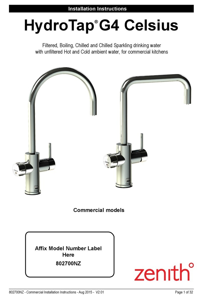
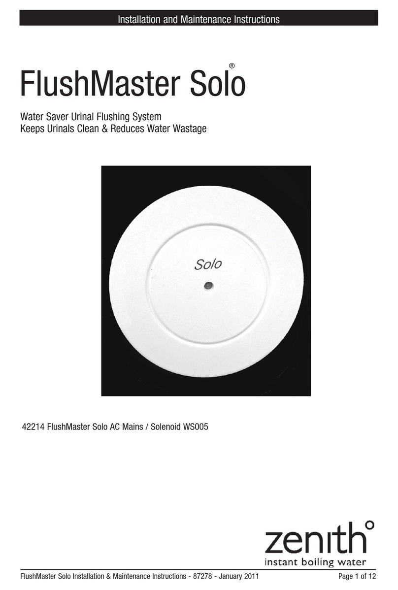
Zenith Surgeon 42226NZ User manual

Page 1 of 8 81424NZ June 2012 v1.01
Installation and Operating Procedures
Aqua Sense Taps
Automatic Taps - Deck and Wall Models.
AquaSense taps are suitable for use in Ablution troughs; Basins and Kitchen sinks
Wall installation model
Deck installation model
Wall Mounted (battery) Model Code: 42226NZ (Surgeon)
Wall Mounted (mains) Model Code: 42225NZ (Surgeon)
Deck Mounted (battery) Model Code: 42211NZ
Deck Mounted (mains) Model Code: 42208NZ
Wall Mounted (battery) Model Code: 42222NZ
Wall Mounted (mains) Model Code: 42223NZ
High Neck (battery) Model Code: 42229
Note: Surgeon models have a 20 second run-on after use.
High Neck model

Page 2 of 8 81424NZ June 2012 v1.01
Contents
Contents . . . . . . . . . . . . . . . . . . . . . . . . . . . . . . . . . . . 3
General Fitting Instructions . . . . . . . . . . . . . . . . . . . . . 3
Components . . . . . . . . . . . . . . . . . . . . . . . . . . . . . . . . 4
Installation Details . . . . . . . . . . . . . . . . . . . . . . . . . . . . 4, 5
Trouble Shooting . . . . . . . . . . . . . . . . . . . . . . . . . . . . . 6
Maintainence. . . . . . . . . . . . . . . . . . . . . . . . . . . . . . . . 6
End of Disposal . . . . . . . . . . . . . . . . . . . . . . . . . . . . . . 6
Warranty Information . . . . . . . . . . . . . . . . . . . . . . . . . . 8
NOTE:
It is the installers responsibility to ensure the installation complies with AS/
NZS3500.1, AS/NZS3500.2, AS/NZS3500.4.1, AS/NZS3500.4.2 and local water
authority regulations.
Contents

Page 3 of 8 81424NZ June 2012 v1.01
General Fitting Instructions.
1. Preparation
You must read these instructions thoroughly before attempting to install this tap. First check the
solenoid valve supplied is suitable for the site water pressure and conditions. The standard valve
requires 50kPa - 800kPa water pressure and 5º - 55º C water temperature. If your water pressure is
outside the stated range please contact the manufacturer.
2. Pre-Fitting
First turn off the water supply. If possible select an upright position for the valve. (As shown in
diagrams) check correct water flow direction when installing solenoid valve. Ensure there is sufficient
room to fit the tap head assembly and enough clearance for the 1” spigot and locating peg to fit
without interference. Fitting an isolation valve, in-line filter, double check valve, prior to the solenoid
valve is mandatory.
3. Installation
Cut the pipework with tube cutters, remove sharp edges and burrs. Purge pipe work to remove all
loose debris. Fit filter, isolation valve, double check valve and solenoid valve. Check all plumbing
joints are secure. Take care not to over-tighten any joints. Now fit the sensor tap faucet to the required
position in the worktop, sink or wall. The sensing distance for standard wall mounted tap is 150mm or
200mm for the surgeon’s model. To prevent any nuisance sensing, keep a 100mm distance from sink
base to Sensing Range lowest point (see fig.1 and fig.2). Secure the faucet with the nut and clamps
provided.
Important:where ever possible you must use the base fixing pins supplied with the faucet.
Ensure the flow restrictor in the tap outlet is adequately secured to prevent removal by hand. Firmly
secure the flexible water supply hose from the faucet to the solenoid valve and turn on the water
supply and check for leaks.
4. Plug and Socket Connections
CAUTION: Mount the battery box / Transformer with care, position where the risk of damage or
moisture intrusion is minimal. Ensure the battery pack or powersupply is left disconnected at this
stage, all cable sockets and plug connections are clean and dry. Then connect firmly and ensure that
the plug and sockets are secured with the barrel nuts on the fittings.
5. Final Test.
Connect the battery pack or power supply unit. The sensor should now activate the solenoid when
your hands are placed under the sensing area.
I
mportant
i
nsta
ll
at
i
on
d
eta
il
s
f
or wa
ll
mount
Minimum 250mm
100mm
150mm
Sink Base
Tap Spout
Sensing Range
Important installation details for wall mount
taps to avoid reflection problems.
Mininum 300mm
100mm
Sink Base
Tap Spout
Sensing Range
200mm
Fig.2 Surgeon ModelFig.1 Standard Model

Page 4 of 8 81424NZ June 2012 v1.01
Components
SUPPLIED:
1.Wall or Deck mounted Tap
with fixing nut and washers.
2. AC or DC Power supply
3. 6 V DC Latching Valve
4. Brass Nipple Nut and Olive
5. JG 15mm X 1/2 BSP adapter
Installation Details
AC Power supply
JG adapter Latching Valve (6 V DC)
Brass Nipple, Nut & Olive
Inlet - Flow direction - from
isolating valve and double
check valve (not supplied)
Flexible hose (Tap)
connection
NOT SUPPLIED:
1. Isolation valve
2. Double check valve.
3. Mixing valve (optional)
4. In line filter
Outlet -
(to Tap)
Wall installation detail Deck installation detail
Important installation details for wall
mount taps to avoid reflection problems.
Clinical Basins
150-200mm
Scrub Troughs
250mm-300mm
Recommended Distance
The minimum recommended distance from the tap spout
to the sink base is normally 250mm for basins or 300mm for
troughs.
This will be greater if there is excessive reflection which can be
caused by bright surfaces such as chromed wastes and/or
Tap spout
Sink base

81424NZ June 2012 v1.01 Page 5 of 8
Installation details
B
B
B
240V PSU
PSU connector
D624
T connector
Water
Isolation Valve*
Filter/Y-
Straner*
Solenoid
valve
Pex hose
D624
T Connector
D632/1 Extension cable
(Optional if cable
doesn’t reach)
Fixings & washers
Mixed water supply
D623
Splitter lead
Multi / AC mains Installation
NOTE: You must only use the Zenith power supply unit. The use of an
alternative unit may cause damage.
TAP1 TAP2 TAP3
Installation details
Power specifications:
Input: 220 - 240 V AC
Current: 0.3 A
Freq.: 50 - 60 Hz.
Output: 6 V DC
Instructions for Attaching Colour Coded Sticker
on AquaSense Tap
Attach Colour Coded
Temperature Sticker
at the front face of the
Tap’s spout.
NOTE:
Plumber must attach
the appropriate colour
coded sticker compliant
to local Water Regulatory
requirements to indicate
the water temperature
dispensed by the Tap.
Push together Rotate fixing against thread to lock connection

Page 6 of 8 81424NZ June 2012 v1.01
Fault Remedy
Tap will not operate
Check electrical connections, Check fuses (mains models only), Check for input voltage (6VDC), Check / Clean
all connections, Check for cable damage, Dis-connect power supply and re-connect after 30 seconds, Check
water is on and flowing, Check solenoid valve is fitted correctly, Check valve for operation, Check for debris in
valve, Water pressure is too low / high check pressure reading.
Tap operates
in reverse.
(Runs when hands
are not present)
Reversed valve polarity (Contact manufacturer)
Tap operates
intermittently
Clean sensor lens with non-abrasive material only, Tap may be installed too close to a R.F. interference source,
Tap may be installed too close to very bright lighting or highly reflective surroundings,
Water pressure may be too low for valve to operate reliably (min 50kPa required),
Voltage too low check output supply (power supply unit or battery, Lithium only)
Trouble Shooting
In order to help preserve our environment we ask that you dispose of this product correctly. Please contact your local
city council for collection centre details.
End of Life Disposal
Maintenance
Replacement
rubber for
diaphragm
Valve Diaphragm Replacement
Isolate power and water supply.
Remove fixing clip on top of latching valve coil by levering up clip with screw
driver and clicking back until clip releases from shaft.
Lift coil, spring clip and spacer from latching valve shaft.
Carefully undo the 4 screws retaining the valve housing. When the last screw
is about to be released, grip the valve body and top section as it is spring
loaded.
Carefully separate the top section containing the spring and plungers from the
lower body. The diaphragm should now be visible. Lift it out of position.
Remove the centre plastic piece from the rubber diaphram. Fit the new
diaphram to the plastic centre. Replace it in the same orientation.
Re-assemble in the reverse of above. Note the position of all parts in the
diaphragm for correct assembly. To order quote Zenith part number 90279NZ
Diaphram Kit.
The valve will require periodic cleaning and servicing. please contact Zenith
for servicing.
For general cleaning do not use abrasive cleaners or materials, only use soap
and water or non-abrasive cleaners.

Page 7 of 8 81424NZ June 2012 v1.01
This page intentionally left blank

Contact:
Zip Heaters (Aust) Pty. Ltd.
ABN 46 000 578 727
67 Allingham Street, Condell Park NSW 2200
Postal: Locked Bag 80, Bankstown 188
Zip AquaSense tap distributed by Zip Heaters (Aust.) Pty Ltd.
Manufactured by Dart Valley services UK
Website: WWW.zipheaters.com
Facsimile(02) 9796 3858
Telephone(02) 9796 3100
Free Call 1 800 638 633
Page 8 of 8 81424NZ June 2012 v1.01
Head Office
Zenith Heaters Limited,
Unit 2/15 Moselle Avenue,
Henderson.
Auckland. 0610
New Zealand.
www.zenithheaters.co.nz
Telephone: 0800 558055
Facsimile: 0800 559055
Warranty
Normal
warranty Extended
warranty Pro-Rata warranty
on main Tank
1yr 2yr 3yr 4yr 5yr
Domestic
HydroTap Parts & Labour Parts & Labour replacement
@25%rrp replacement
@33%rrp replacement
@50%rrp
HydroBoil Parts & Labour Parts & Labour replacement
@25%rrp replacement
@33%rrp replacement
@50%rrp
AutoBoil Parts & Labour Parts only replacement
@25%rrp
Commercial
HydroTap Parts & Labour Parts only
All other Parts & Labour
Warranty table effective from 1st April 2008.
Full warranty details may be found on the website
Registering Your Purchase
Registering your Zenith installation on the website may help to establish date of installation should it become necessary to
service the appliance under terms of the Zenith warranty. To register your installation go to www.zenithheaters.co.nz and
look under the heading “Warranty”, or forward the completed product registration form (enclosed) to your nearest Zenith
head office.
NOTE: Extended warranty and Pro-Rata warranty will only be available on products which have been registered with
Zenith Heaters Ltd., head office
As Zenith Heaters Limited policy is one of continuous product improvement, changes to specifications may be made
without prior notice. Images in this booklet have been modified and may not be true representations of the finished
goods.
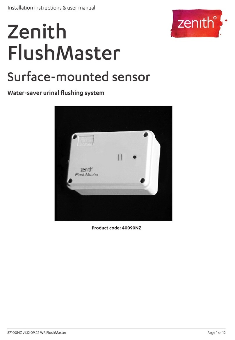
This manual suits for next models
6
Table of contents
Other Zenith Plumbing Product manuals

Zenith
Zenith FlushMaster 40090NZ Manual

Zenith
Zenith HydroTap G5 UltraCare BCU 40 User manual

Zenith
Zenith HydroTap G5 Instruction Manual

Zenith
Zenith HydroTap G4 User manual

Zenith
Zenith Miniboil Manual

Zenith
Zenith FlushMaster Solo 42214 User manual

Zenith
Zenith HydroTap G5 User manual
Zenith
Zenith ChillTap Residential Manual

Zenith
Zenith HydroTap G4 Celsius Series User manual

Zenith
Zenith HydroTap Classic User manual