manuals.online logo
Brands
  1. Home
  2. •
  3. Brands
  4. •
  5. Zephyr
  6. •
  7. Ventilation Hood
  8. •
  9. Zephyr Bogart EBO-E36ASX Installation guide

Zephyr Bogart EBO-E36ASX Installation guide

This manual suits for next models

1

Other Zephyr Ventilation Hood manuals

Zephyr Venezia ZVE-E30AS Installation guide

Zephyr

Zephyr Venezia ZVE-E30AS Installation guide

Zephyr Typhoon AK2100CS Installation guide

Zephyr

Zephyr Typhoon AK2100CS Installation guide

Zephyr Tempest AK0714 Installation guide

Zephyr

Zephyr Tempest AK0714 Installation guide

Zephyr Luce Island ZLC-M90AS Installation guide

Zephyr

Zephyr Luce Island ZLC-M90AS Installation guide

Zephyr ZMD-E42AS Installation guide

Zephyr

Zephyr ZMD-E42AS Installation guide

Zephyr Slope ESL-M90AS Installation guide

Zephyr

Zephyr Slope ESL-M90AS Installation guide

Zephyr Typhoon AK2136CS Installation guide

Zephyr

Zephyr Typhoon AK2136CS Installation guide

Zephyr Titan AK7636BS Installation guide

Zephyr

Zephyr Titan AK7636BS Installation guide

Zephyr Siena Pro ZSP-E36BS Installation guide

Zephyr

Zephyr Siena Pro ZSP-E36BS Installation guide

Zephyr Verona ZVO-E30BG Installation guide

Zephyr

Zephyr Verona ZVO-E30BG Installation guide

Zephyr Breeze II AK1200x Installation guide

Zephyr

Zephyr Breeze II AK1200x Installation guide

Zephyr ALU-E63 Operating and maintenance manual

Zephyr

Zephyr ALU-E63 Operating and maintenance manual

Zephyr Bogart EBO-E42ASX Installation guide

Zephyr

Zephyr Bogart EBO-E42ASX Installation guide

Zephyr Tempest II AK7500ASX Installation guide

Zephyr

Zephyr Tempest II AK7500ASX Installation guide

Zephyr Twister Installation guide

Zephyr

Zephyr Twister Installation guide

Zephyr Roma Island ZRM-E36BS Installation guide

Zephyr

Zephyr Roma Island ZRM-E36BS Installation guide

Zephyr Roma Groove ZRG-E30BS Installation guide

Zephyr

Zephyr Roma Groove ZRG-E30BS Installation guide

Zephyr Ravenna ZRV-E30AGC Installation guide

Zephyr

Zephyr Ravenna ZRV-E30AGC Installation guide

Zephyr ATI-M90ASX User manual

Zephyr

Zephyr ATI-M90ASX User manual

Zephyr AK9028AS Installation guide

Zephyr

Zephyr AK9028AS Installation guide

Zephyr EAL-E42ASX User manual

Zephyr

Zephyr EAL-E42ASX User manual

Zephyr Z1C-00SU User manual

Zephyr

Zephyr Z1C-00SU User manual

Zephyr AK2000 Installation guide

Zephyr

Zephyr AK2000 Installation guide

Zephyr Titan Island AK7742AS Installation guide

Zephyr

Zephyr Titan Island AK7742AS Installation guide

Popular Ventilation Hood manuals by other brands

Gorenje S3 IHGC963S4X manual

Gorenje

Gorenje S3 IHGC963S4X manual

KOBE ISX2136SQB-1 Installation instructions and operation manual

KOBE

KOBE ISX2136SQB-1 Installation instructions and operation manual

U.S. Products ADVANTAGE-100H Information & operating instructions

U.S. Products

U.S. Products ADVANTAGE-100H Information & operating instructions

Kuppersberg DUDL 4 LX Technical Passport

Kuppersberg

Kuppersberg DUDL 4 LX Technical Passport

Framtid HW280 manual

Framtid

Framtid HW280 manual

Thermador HGEW 36 FS installation manual

Thermador

Thermador HGEW 36 FS installation manual

Electrolux LFT769X user manual

Electrolux

Electrolux LFT769X user manual

AEG X69453MVO UK user manual

AEG

AEG X69453MVO UK user manual

Broan B5836SS manual

Broan

Broan B5836SS manual

Heinner HDCH-6060RGBK quick start guide

Heinner

Heinner HDCH-6060RGBK quick start guide

Baumatic AS35SS instruction manual

Baumatic

Baumatic AS35SS instruction manual

Franke FTF 604 XS V2 Instructions for use and installation

Franke

Franke FTF 604 XS V2 Instructions for use and installation

Best UCB3I30SBW installation instructions

Best

Best UCB3I30SBW installation instructions

Gram EFU 503-90 X instruction manual

Gram

Gram EFU 503-90 X instruction manual

CIARRA CBCS6803 Installation and user manual

CIARRA

CIARRA CBCS6803 Installation and user manual

sauter SHG501 Instructions for installation and use

sauter

sauter SHG501 Instructions for installation and use

Franke 392-17 User instructions

Franke

Franke 392-17 User instructions

FALMEC Polar Black 35 Instruction booklet

FALMEC

FALMEC Polar Black 35 Instruction booklet

manuals.online logo
manuals.online logoBrands
  • About & Mission
  • Contact us
  • Privacy Policy
  • Terms and Conditions

Copyright 2025 Manuals.Online. All Rights Reserved.

JAN06.0101
2
PLEASE READ ENTIRE INSTRUCTIONS BEFORE PROCEEDING.
INSTALLATION MUST COMPLY WITH ALL LOCAL CODES.
IMPORTANT: Save these Instr ctions for the Local Electrical Inspectors se.
INSTALLER: Please leave these Instr ctions with this nit for the owner.
OWNER: Please retain these instr ctions for f t re reference.
Safety Warning: T rn off power circ it at service panel and lock o t panel, before wiring this appliance.
Req irement: 120 V AC, 60 Hz. 15 or 20 A Branch Circ it
E page 2
F page 23
S page 45
APPROVED FOR RESIDENTIAL APPLIANCES
FOR RESIDENTIAL USE ONLY
READ AND SAVE THESE INSTRUCTIONS
3
www.zephyronline.com
Table of Contents
Important safety Notice ..................................................................... 4
Electrical & Installation req irements ............................................. 5
Electrical requirements .............................................................. 5
Before installing the hood ........................................................... 5
List of Materials ................................................................................. 6
Parts supplied: ........................................................................... 6
Parts not supplied ...................................................................... 6
Dimensions and clearances.............................................................. 7
Installation Instr ctions ..................................................................... 8
Venting methods ........................................................................ 8
Preparation ................................................................................ 8
Installation - D ctwork Calc lation Sheet ...................................... 9
Installation ....................................................................................... 10
Electrical connection ................................................................ 12
Description of the hood ................................................................... 14
Control Ball .............................................................................. 15
emote Control ........................................................................ 16
Maintenance .................................................................................... 17
Cleaning ................................................................................... 17
Grease filter ............................................................................. 17
eplacing the light bulb: ........................................................... 17
Trouble Shooting ...................................................................... 18
Warranty ........................................................................................... 19
List of Parts and Accessories .......................................................... 20
4
Important safety Notice
CAUTION:
FOR GENERAL VENTILATING USE ONLY. DO NOT USE TO EXHAUST HAZARDOUS OR EXPLOSIVE MATERIALS OR
VAPORS.
WARNING
TO REDUCE THE RISK OF FIRE, ELECTRIC SHOCK, OR INJURY TO PERSONS, OBSERVE THE FOLLOWING:
A. Use this unit only in the manner intended by the manufacturer. If you have questions, contact the manufacturer.
B. Before servicing or cleaning the unit, switch power off at service panel and lock service panel disconnecting means to
prevent power from being switched on accidentally. When the service disconnecting means cannot be locked,
securely fasten a prominent warning device, such as a tag, to the service panel.
C. Installation Work and Electrical Wiring ust Be Done By Qualified Person(s) In Accordance With All Applicable Codes
& Standards, Including Fire-rated Construction.
D. Sufficient air is needed for proper combustion and exhausting of gases through the flue (chimney) of fuel burning
equipment to prevent back- drafting. Follow the heating equipment manufacturers guideline and safety standards such
as those published by the National Fire Protection Association (NFPA), the American Society for Heating, Refrigeration
and Air Conditioning Engineers (ASHRAE), and the local code authorities.
E. When cutting or drilling into wall or ceiling, do not damage electrical wiring and other hidden utilities.
F. Ducted systems must always be vented to the outdoors.
CAUTION:
To r duc risk of fir and to prop rly xhaust air, b sur to duct air outsid - do not v nt xhaust air into spac s
within walls, c ilings, attics, crawl spac s, or garag s.
WARNING
TO REDUCE THE RISK OF FIRE, USE ONLY METAL DUCT WORK.
Install this hood in accordance with all requirements specified.
WARNING
To R duc Th Risk Of Fir Or El ctric Shock, Do Not Us This Hood With Any Ext rnal Solid Stat Sp d
Control D vic .
WARNING
TO REDUCE THE RISK OF A RANGE TOP GREASE FIRE.
a) Never leave surface units unattended at high settings. Boilovers cause smoking and greasy spillovers that may ignite.
Heat oils slowly on low or medium settings.
b) Always turn hood ON when cooking at high heat or when flambeing food (i.e. Crepes Suzette, Cherries Jubilee,
Peppercorn Beef Flambe).
c) Clean ventilating fans frequently. Grease should not be allowed to accumulate on fan or filter.
d) Use proper pan size. Always use cookware appropriate for the size of the surface element.
WARNING
TO REDUCE THE RISK OF INJURY TO PERSONS, IN THE EVENT OF A RANGE TOP GREASE FIRE, OBSERVE THE
FOLLOWING:
a) S OTHER FLA ES with a close-fitting lid, cookie sheet, or other metal tray, then turn off the gas burner or the electric
element. BE CAREFUL TO PREVENT BURNS. If the flames do not go out immediately, EVACUATE AND CALL THE
FIRE DEPART ENT.
b) NEVER PICK UP A FLA ING PAN - you may be burned.
c) DO NOT USE WATER, including wet dishcloths or towels - a violent steam explosion will result.
d) Use an extinguisher ONLY if:
1) You know you have a class ABC extinguisher, and you already know how to operate it.
2) The fire is small and contained in the area where it started.
3) The fire department is being called.
4) You can fight the fire with your back to an exit.
OPERATION
a. Always leave safety grills and filters in place. Without these components, operating blowers could catch onto hair,
fingers and loose clothing.
The manufacturer declines all responsibility in the event of failure to observe the instructions given here for installation,
maintenance and suitable use of the product. The manufacturer further declines all responsibility for injury due to
negligence and the warranty of the unit automatically expires due to improper maintenance.
* NOTE: Please check our website for revisions before doing any custom work.
READ AND SAVE THESE INSTRUCTIONS
5
www.zephyronline.com
Electrical & Installation requirements
ELECTRICAL REQUIREMENTS
Important:
Observe all governing codes and ordinances.
It is the customers responsibility:
 To contact a qualified electrical installer.
 To assure that the electrical installation is adequate and in conformance with National Electrical Code, ANSI/NFPA 70
 latest edition*, or CSA Standards C22.1-94, Canadian Electrical Code, Part 1 and C22.2 No.0- 91 - latest edition**
and all local codes and ordinances.
If codes permit and a separate ground wire is used, it is recommended that a qualified electrician determine that the
ground path is adequate.
Do not ground to a gas pipe.
Check with a qualified electrician if you are not sure range hood is properly grounded.
Do not have a fuse in the neutral or ground circuit.
IMPORTANT:
Save Installation Instructions for electrical inspectors use.
The range hood must be connected with copper wire only.
The range hood should be connected directly to the fused disconnect (or circuit breaker) box through metal electrical
conduit.
Wire sizes must conform to the requirements of the National Electrical Code ANSI/NFPA 70  latest edition*, or CSA
Standards C22.1-94, Canadian Electrical Code Part 1 and C22.2 No. 0- 91 - latest edition** and all local codes and
ordinances.
A U.L.- or C.S.A.-listed conduit connector must be provided at each end of the power supply conduit (at the range hood
and at the junction box).
Copies of the standards listed may be obtained from:
* National Fire Protection Association Batterymarch Park Quincy, Massachusetts 2269
** CSA International 85 1 East Pleasant Valley Road Cleveland, Ohio 44131-5575
BEFORE INSTALLING THE HOOD
1. For the most efficient air flow exhaust, use a straight run or as few elbows as possible.
CAUTION: Vent unit to outside of building, only.
2. At least two people are necessary for installation.
3. The hood is fitted with Screws and Drywall Anchors suitable for most surfaces, consult a Qualified Installer, check if
they perfectly fit with your cabinet/wall.
4. Do not use flex ducting.
5. COLD WEATHER installations should have an additional backdraft damper installed to minimize backward cold air
flow and a nonmetallic thermal break to minimize conduction of outside temperatures as part of the ductwork. The
damper should be on the cold air side of the thermal break.
The break should be as close as possible to where the ducting enters the heated portion of the house.
6. ake up air: Local building codes may require the use of ake-Up Air Systems when using Ducted Ventilation
Systems greater than specified CF of air movement.
The specified CF varies from locale to locale. Consult your HVAC professional for specific requirements in your area.
6
List of Materials
PARTS SUPPLIED:
 Blower unit housing
 Hood canopy
 etal filter x 1
 Halogen light bulb x 2
 Duct covers
 Remote Control
 Hardware Packet:
Allen spanner x 1
Lower support bracket
Tem p l ate
Use, Care and Installation guide
2,9x6,5 screws x 4 (to fix duct cover)
6x20 screws x2 + bushings (to fix vapour screen)
6x70 screws x 2 (to fix duct cover support bracket)
10x60 wall anchors x 2 (to fix duct cover support bracket)
5x45 screws x 3 (2 to fix lower support bracket + 1 to fix blower unit)
PARTS NOT SUPPLIED
 Duct, conduit and all tools required for installation.
Ductl ss R circulating Kit
to be used only in the Ductl ss (r circulating) v rsion
includ s: charcoal filter, charcoal filter support and fixing bracket, deflector
Int rnal blow r
To be used only in case of Internal blower installation.
In-lin blow r
To be used only in case of in-line blower installation
Nois r duction spong
Note: may be already included on internal/in-line blower package.
CAUTION
To reduce the risk of fire and electric shock, install this rangehood only with integral blowers mod. EBI-600A rated 120V
60Hz 450W or with remote blowers mod. EBN-1100A rated 120V 60Hz 900W, manufactured by Elica.
7
www.zephyronline.com
Dimensions and clearances
19" 11/16
5/8" 2"min
7" 1/2*
Side
Cabinet Side
Cabinet
35" 7/16
min. cabinets opening widths
24" to 32"
bottom o canopy
to cooking sur ace
ceiling
CenterLine
14" 6/8
26"
12" 12"
Ducting
and conduit
area
passage(Duct
bends are not
considered)
22" 1/4
42" - 36"
15" 3/4
8"
13"
5" 3/8
min 35" 13/16*
max 49" 7/16*
25" 11/16
min 35" 13/16
max 43" 2/16
* Ductl ss (r circulating) v rsion ONLY
Not : if n c ssary ord r th prop r duct cover
extension kit.
8
Installation Instructions
Closely follow the instr ctions set o t in this man al.
All responsibility, for any eventual inconveniences, damages or fires caused by not complying with the instructions in this
manual, is declined.
VENTING METHODS
The hood is equipped with a transition B for discharge of fumes to the outside (Ducting v rsion).
Should it not be possible to discharge cooking fumes and vapour to the outside, the hood can be used in the Ductl ss
(r circulating) v rsion. Attach a charcoal filter and the deflector F on the duct cover support bracket G. Fumes and
vapors are recycled through the top grille H by means of a duct connected to the transition B and the transition mounted
on the deflector F.
NOTE: For ductl ss (r circulating) v rsion only: purchas th Ductl ss R circulating Kit.
Minimum Duct Siz (Ducting/Ductl ss v rsion): 8" Round Pip .
PREPARATION
Do not cut a joist or stud unless absolutely necessary. If a joist or stud must be cut, then a supporting frame must be
constructed.
Fittings material is provided to secure the hood to most types of walls/ceilings.
However, a qualified technician must verify suitability of the materials in accordance with the type of wall/ceiling.
The weight of the hood is:
Before making cutouts, make sure there is proper clearance within the ceiling or wall for exhaust vent.
Hood installation height above cooktop is the users preference. The lower the hood above the cooktop, the more efficient
the capturing of cooking odors, grease and smoke.
Th hood shall b install d at 24" minimum to 32" abov th count rtop.
Check your ceiling height and the hood height maximum before you select your hood.
B
Pip
F-H-G
Ducting v rsion
with int rnal blow r
Pip
B
Pip
B
Ducting v rsion
with In-lin blow r
Roof pitch w/
Flashing and cap
D ctless
(recirc lating)
version
Roof pitch w/
Flashing and cap R mot
v ntilator
Side wall cap
with gravity
damper
B
Pip
9
www.zephyronline.com
Installation - Ductwork Calculation heet
3 1/4  x 1 
Rect.,
straight
6  Round,,
straight
7", 8
Round,,
straight
3 1/4  x 1 
Rect.9 °
elbow
3 1/4  x 1 
Rect.45°
elbow
3 1/4  x 1 
Rect.9 °
flat elbow
3 1/4  x 1 
Rect.
wall cap
with damper
3 1/4  x 1 
Rect.to
6  round
transition
3 1/4  x 1 
Rect.to
6  round
transition
9 ° elbow
6  Round,,
9 ° elbow
6  Round,,
45°elbow
1 Ft. x ( ) =
1 Ft. x ( ) =
1 Ft. x ( ) =
15 Ft. x ( ) =
9 Ft. x ( ) =
24 Ft. x ( ) =
3 Ft. x ( ) =
5 Ft. x ( ) =
15 Ft. x ( ) =
15 Ft. x ( ) =
9 Ft. x ( ) =
Ft.
Ft.
Ft.
Ft.
Ft.
Ft.
Ft.
Ft.
Ft.
Ft.
Ft.
6" Round
wall cap
with damper
6 Round,
roof cap
6 Round to
3 1/4  x 1 
rect.
transition
6 Round to
3 1/4  x 1 
rect.
transition
9 ° elbow
7", 8" round
9 ° elbow
7", 8" round
45° elbow
7", 8" Round
wall cap
with damper
7", 8"
Round,
roof cap
7 Round to
3 1/4  x 1 
rect.
transition
6 Round to
3 1/4  x 1 
rect.
transition
9 ° elbow
3 Ft. x ( ) =
3 Ft. x ( ) =
1 Ft. x ( ) =
16 Ft. x ( ) =
15 Ft. x ( ) =
9 Ft. x ( ) =
3 Ft. x ( ) =
3 Ft. x ( ) =
8 Ft. x ( ) =
15 Ft. x ( ) =
Ft.
Ft.
Ft.
Ft.
Ft.
Ft.
Ft.
Ft.
Ft.
Ft.
Duct pieces Equivalent number
lenght x used = Total
Duct pieces Equivalent number
lenght x used = Total
Subtotal column 2 =
Subtotal column 2 =
Total ductwork =
Subtotal column 1 =
Maximum Duct Length: For satisfactory air movement, the total
duct length should not exceed 1 equivalent feet.
10
Installation
1. If possible, disconnect and move freestanding or
slide-in range from cabinet opening to provide easier
access to rear wall. Otherwise put a thick, protective
covering over countertop, cooktop or range to
protect from damage or dirt. Select a flat surface for
assembling the unit. Cover that surface with a
protective covering and place all canopy hood parts
and hardware in it.
2. Determine and mark the centerline on the wall where
the canopy hood will be installed.
3. Select a mounting height comfortable for the user
and mark on wall behind cooktop.
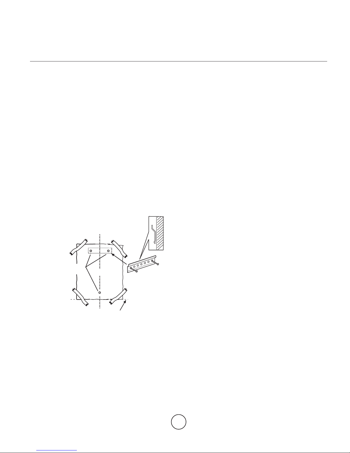
4. Tape template, matching center-line and hood
bottom as shown in Figure below.
5. Place the lower support bracket on the template
making it coincide with the traced triangle, mark
center of two fastener location and one lower
fastener location then remove template.
C
L
centerline
mounting
height
reference
fasteners
locations lower
support
bracket
6. ark wall with horizontal line 1" above highest and
1" below lowest fastener location.
7. Find studs behind drywall by tapping wall or using a
stud finder. ark the center of the studs with a
vertical line to the right and left of the marked
fastener location.
8. Not : all fastener location must span the studs
otherwise proceed as follows:
Cutout drywall along marked lines. Install each
necessary between studs firmly flush with already
existing stud front. ake sure all mounting screws
will anchor to added studs. Replace drywall and
refinish.
9. Determine and make all necessary cuts in the wall
for the vent system. Install the vent system before
the canopy hood. See Venting methods and
Dimensions and clearance paragraphs.
Not - for Ductl ss - r circulating - installations:
Vent system is not required.
10. Determine the required height for the conduit and cut
a 1-1/4" (3.2 cm) hole at this location.
Run wires through hole according the National
Electrical Code or CSA Standards and local codes
and ordinances.
Note: If a In-line blower installation is required/
needed, then provide an additional hole/conduit.
There must be enough power supply cable from the
fused disconnect (or circuit breaker) box to make the
connection in the hoods Junction box/es.
Use caulking to seal all openings.
Do Not turn on power until installation is completed.
11.Remark center line and hood bottom on same
location as before and tape template on wall as in
step 4 above.
12. ount the lower support bracket with wood screws
(supplied in mounting hardware kit) on locations
marked on template, then remove template.
13.Install duct cover support bracket to wall flush to
ceiling with drywall anchors supplied (the duct cover
support bracket should be installed about 1/8 (3mm)
away from the ceiling).
For Ductl ss (r circulating) installations
Install the deflector (available as an extra kit) under
the duct cover support bracket.
14. Not : disregard this step if intending to install a in-
line blower.
Purchase and install the Internal blower (see
paragraph Before installing the hood - Parts not
supplied for model reference).