ZERO GRAVITY PHOENIX Operating instructions

ELECTRO-PNEUMATIC PHOENIX
Operating and Maintenance Manual
PHOENIX

2
Electro-Pneumatic Operation
TABLE OF CONTENTS
Section
Number
Description
Page
Number
Standard and Limited Warranty
3
Packing List
4
Installation Guide
Filter Element Installation
5
9
Operating Manual
10
1.0
Components
11
1.1
Body
11
1.2
Motor/Gearbox
11
1.3
Opto Disc
11
1.4
Indexing Valve
11
1.5
Backwash Valve
11
1.6
Element Selection
11
1.7
Discharge Regulating Valve
12
1.8
Control System
12
1.8.1
Control Cover
12
1.8.2
Circuit Board
12
1.9
Differential Pressure Switch
13
2.0
2.1
Operating Guidelines
Filter Operation
14
14
2.2
Differential Pressure Switch
14
2.3
Backwash Duration Timer
15
2.4
Backwash Interval Timer
16
2.5
Fault Conditions
16
3.0
Filter Start-Up
18
3.1
Backwash Cycle
18
4.0
Recommended Maintenance
19
4.1
Removal, Inspection and Cleaning of Filter Elements
19
4.2
Replacement of Filter Elements
20
4.3
Removal of Indexing Valve
20
4.4
Replacement of Indexing Valve
21
4.5
Setting Up Opto Disc
21
5.0
Filter Diagnostics
23
5.1
Fault Indication
23
5.2
Fault Finding
24
6.0
Spare Parts
25
Exhibit 1
Pressure/Flow Diagram
26
Exhibit 2
Circuit Board Layout (ZG 10086)
Exhibit 3
General Assembly Diagram (ZG 10250)
Exhibit 4
Cut-Away Diagram (ZG 10254)
Version 3.0
January 2008

3
Standard and Limited Warranty
Seller warrants that title to goods sold hereunder is unencumbered at time of sale. All other
warranties are expressly disclaimed including, but not limited to, merchantability, fitness for
purpose, and all other warranties, express or implied.
Seller expressly disclaims any liability for damages, actual, consequential, incidental or
otherwise, for injury to property of buyer, its agent or third persons in custody of goods sold
hereunder.
Seller may determine to repair or replace any defects in goods of its own manufacture,
which arise from defective materials or workmanship during the twelve (12) months, or (60)
months on the filter elements, following the date of tender of delivery to the end purchaser if
buyer gives seller timely written notice with a description of the basis for claim.
Seller may refund amounts paid by buyer without other liability to buyer. The buyer
acknowledges and agrees that the limitations of warranty, liability and remedy are fair and
not unconscionable and the sole and exclusive remedies afforded at law with all other
statutory and common law remedies being hereby waived. A claim under the warranty by
the buyer for repair or replacement of goods shall be timely filed with the seller in
accordance with the written procedures of the seller in effect at the time of any such claim.

4
PHOENIX
Electro-Pneumatic Operation
PACKING LIST
Contents:
1. Stainless steel filter housing (Phoenix) complete with controls and (6) filter elements and
corresponding O rings.
2. Operating manual & installation guide
Please read the “Installation Guide” provided before installing filter to system.

5
PHOENIX
Electro-Pneumatic Operation
INSTALLATION GUIDE
POWER SUPPLY
The power supply required for the filter is 24 VDC @ 1 Amp
PNEUMATIC CONNECTIONS
An 80 psi, clean and dry compressed air supply should be made to the ¼” connector on the
Backwash Valve actuator. There is no need to run exhaust lines from the actuator, as
snubbers have been fitted to the actuator for this purpose.
DIFFERENTIAL PRESSURE (DP) SWITCH
The filter is supplied with a DP switch connected hydraulically and electrically to the filter;
the operating range of this switch is from 2 to 45 psi (differential pressure). Should the
differential pressure across the filter exceed 45 psi, damage may occur to the switch.
The DP switch is wired using the common ( C ) and normally closed contacts (NC).
NOTE: With an optional dual indicator Differential Pressure switch, the left set of terminals
are related to the lowest dial setting (backwash set point) and the right set of terminals are
for the highest setting (high set point).
PIPE CONNECTIONS
The filter inlet (bottom) and discharge (side) are 3 inch, 4 bolt flanges (ANSI 150 bolt hole
pattern). The backwash connection is a ¾” NPT female which should be plumbed to a
suitable drain or tank capable of handling the system’s pressure. To avoid excessive
pressure drops, which could impair backwash effectiveness, do not run the
backwash line more than 10 feet with the id of the line no less than ¾”.
FILTER SUPPORT
The filter can be either supported at the base of the six pods or at the inlet flange.
DIMENSIONS AND WEIGHT
Weight: Dry = 85 lbs excluding elements and 85 lbs including elements
Wet = 110 lbs (assuming water)

6
OPERATING REQUIREMENTS
The Phoenix filter requires a minimum working pressure of 40 psi. This pressure will ensure
that there is a minimum of 30 psi on the outlet of the filter at time of backwash, e.g. 10 psi
differential pressure at backwash. Correspondingly, if a higher DP set point is desired, then
a higher inlet pressure is required.
PUMP
To achieve the above pressure, it is imperative that the correct pump be chosen to deliver
the required flow at the required pressure. Please contact Zero Gravity Filters for
assistance in pump selection.
REGULATING VALVE
A regulating valve must be fitted on the discharge of the filter, enabling the user to
balance the filter’s pressure and flow rate. At the same time, the regulating valve will
ensure sufficient pressure for backwash, particularly important if the filter discharge is to
atmosphere (i.e. an open tank). Please note: Do not use a butterfly type valve for this
purpose.
ISOLATING VALVES
It is advisable to fit inlet and discharge isolating valves to the filter for ease of maintenance.
GAUGES
Pressure gauges must be fitted to the system to monitor both the inlet and discharge
pressure of the filter. Gauges may be fitted between the pump and filter inlet and between
the filter discharge and regulating valve. Alternatively, there are blanked off ports on the
filter’s inlet to which a 1/4” gauge may be fitted. In addition, to monitor the filter’s outlet
pressure a gauge may be fitted on the bottom surface to where the pods are attached.
INLET STRAINER
A coarse strainer must be fitted to the inlet side of the filter if particulate size is greater than
¼”.

7
Example of Installation:

8
FILTER ELEMENT INSTALLATION
Once the filter has been installed as per the Installation Guide and pressure tested, the filter
elements can now be fitted. To gain access to the inside of the filter to install the filter
elements, please follow the instructions below.
Removing doughnut shaped cover:
1. Remove the 6” filter cover retaining ring and red backing ring.
2. Remove “Clampco” ring clamp coupling from around doughnut shaped filter cover.
3. Remove doughnut shaped filter cover. If difficulty is experienced, gently insert a broad
screwdriver under the outer edge of the filter cover to relieve the “O” seal suction. Insert
the screwdriver more than ¼” to avoid damaging the large “O” ring inside the filter
housing. You will now see six element holders, one in each of the filter pods and the
common discharge port. Cover the discharge port to prevent any ingress of debris and
remove each element holder.
4. Lightly lubricate the “O” rings on the element holders with a site approved lubricant and
attach the filter elements to the element holders by referring to the following drawing.
5. Once the filter elements are attached, place the six filter elements into the pods.
6. Generously lubricate the neck “O” ring.
7. Check that the filter cover “O” ring is correctly located in its groove around the
circumference of the filter body and replace doughnut shaped filter cover.
8. Replace “Clampco” ring clamp, red backing ring and 6” retaining ring, in that order.

9
CAUTION: WHEN FITTING ELEMENTS TO THE ELEMENT HOLDERS, THE
ELEMENTS MUST BE HELD BY THE VERY TOP PORTION OF THE ELEMENT’S
PLASTIC CAGE, ELSE DAMAGE MAY RESULT TO THE ELEMENT OR CAGE
ASSEMBLY. ONCE FITTED THE SCREWS MUST BE CHECKED FOR TIGHTNESS
ONE HOUR AFTER OPERATION.

10
Electro-Pneumatic Phoenix
OPERATING MANUAL
Description
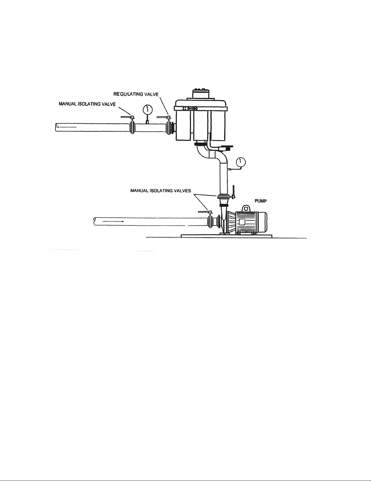
The Phoenix filter is a fully automatic backwashing filter, comprising six patented filter
elements in separate pods surrounding a central inlet chamber. The discharge from each
pod is collected in a common area under the “doughnut” shaped filter cover before leaving
via a common discharge port. The central inlet chamber contains a proprietary indexing
valve, which operates the filter’s backwash. Backwash is controlled by the circuit board
situated inside the filter cover, which in turn powers a 24 VDC electric motor and gearbox
assembly. The motor/gearbox rotates the Indexing Valve while sequentially backwashing
each pod. A pneumatic backwash valve opens and closes with each indexing position.
Operating Parameters
Power Supply: 24 VDC, 1 Amp supply
Minimum Operating Pressure: 40 psi
Maximum Operating Pressure: 100 psi
Maximum Differential Pressure: 40 psi
Static Test Pressure: 230 psi
Maximum Operating Temperature: 135º F (higher temperature ratings available)
Flow Rate: see flow chart (Exhibit 1)
Micron Ratings: 25, 50, 75, 125, 200 and 400 micron.
Minimum Air Pressure: 60 psi
Maximum Air Pressure: 100 psi
Materials Composition
Filter Material
Filter Housing: Stainless steel 304L
Control Cover: Aluminum (non-wetted part)
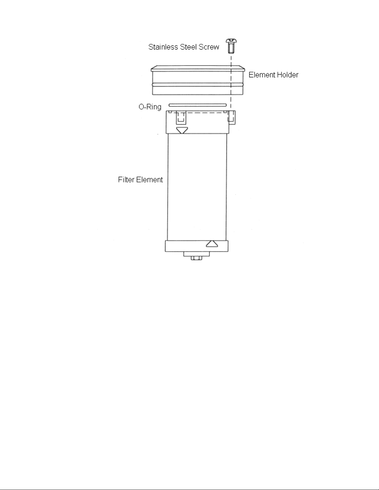
Filter Elements: Stainless steel 316.
Element Holders: Glass filled polypropylene (stainless steel available), stainless
steel screws
Indexing Valve: Stainless steel 304 with Buna, EPDM, or Viton ‘O’ rings and
polyacetal shoe.
Backwash Valve: Chrome plated, brass body, stainless steel 316 ball with PTFE
seats and double acting actuator. Stainless steel wetted parts
available.
DP Switch: One micro switch, brass wetted parts, fitted with visual indicator
and nitrile seals. Upgrades include an additional micro switch,
stainless steel wetted parts, and Viton seals.
‘O’ Rings: Viton standard throughout, Buna and EPDM available.

11
1.0 Components
1.1 Filter Body
Manufactured from stainless steel 304L, the filter body consists of six pods each containing
a filter element and joined by a common inlet and outlet. Also connected to the central
chamber of the filter is the backwash pipe. The inlet and outlet connections are 3” flange,
ANSI 150 bolt hole pattern, and the backwash connection is 3/4” NPT female.
1.2 Motor/Gearbox
The motor/gearbox is fitted on top of the Indexing Valve. The motor/gearbox rotates the
Indexing Valve 360º while backwashing each pod in sequence.
1.3 Opto Disc
A slotted disc is fitted to the top of the motor/gearbox drive shaft, to provide indication to the
circuit board by means of two optical sensors the position of the Indexing Valve.
1.4 Indexing Valve
The Indexing Valve is situated in the central inlet chamber. The motor/gearbox drives this
valve. During backwash, the Indexing Valve rotates to close off the inlet to each pod in
sequence while simultaneously providing access to the ¾” backwash port. Fitted on the
backwash line is a pneumatically operated Backwash Valve that opens and closes with
each index position. The opening of the Backwash Valve allows a reverse flow of clean
liquid to open each element in sequence while flushing the accumulated debris from the
filter element to drain.
1.5 Backwash Valve
The Backwash Valve is pneumatically operated. In the filter position, the valve is closed
and prevents liquid loss from the backwash line. During backwash, the valve opens and
closes with each index position. If there is a fault with the filter (see Section 5.0), the
backwash valve will automatically close.
1.6 Element Selection
Element selection is dependent on the nature of the contaminant in the fluid to be filtered.
As can be seen from the flowchart in Exhibit 1, the smaller the micron size the lower the flow
rate through the filter. Correspondingly, this will also directly affect the clean differential
pressure across the filter.

12
1.7 Discharge Regulating Valve
It is essential to fit a regulating valve on the discharge of the filter for two reasons:
1. To ensure the correct flow rate through the filter, and
2. to provide the necessary head pressure on the filter’s discharge for efficient
backwashing.
1.8 Control System
The control system is located directly beneath the control cover, which is held in place by
two snug fitting “O” rings. The power supply to the circuit board is 24 VDC with a maximum
load of 1 Amp.
The following indicators and controls are provided:
1.8.1 Control Cover
1. Power LED – Illuminates AMBER
when the panel is connected to a live
24 VDC supply.
2. Backwash LED – Illuminates BLUE
when the filter is in backwash
mode.
3. Fault LED – Illuminates when there
is a fault with the filter. For various
faults and indications, refer to
section 2.4.
4. Manual Backwash Button (Hand
Symbol) - Used to manually initiate
a backwash.
5. Backwash Counter - A non-reset
counter which is incremented at the
completion of each backwash.
1.8.2 Circuit Board
Fitted to the vertical circuit board are the following (please refer to Exhibit 2 for a layout
drawing of the board):
a. Backwash Duration Timer (marked WASH) - This timer is used to set the amount of time
that the diverting valve remains stationary at each pod during backwash. Thereby,
controlling the amount of water used to backwash each pod. There are six set-points
beginning at two seconds and increasing by one second to the maximum setting of 7
seconds, please refer to Section 2.2.

13
b. Backwash Interval Timer (marked
TIME) -This timer is used to set the
maximum time between each
backwash. There are six set-points
ranging from 1 minute to 24 hours,
please refer to Section 2.3.
c. Terminal connectors labeled as follows:
DPSW LOW:
To connect from the DP’s ‘Normally Closed’ and ‘Common’ contacts to terminals
1 and 2 on the circuit board.
PWR 24V
For connecting the power supply: Note the (+) and (–) must be connected
correctly. Failure to do so, will result in malfunction of the filter.
WASH N.O.
Volt free contacts providing remote indication when the filter is in backwash mode.
The contacts are normally open and have a maximum load of ½Amp.
FAULT N.O.
Volt free contacts providing remote indication when the filter is in a fault condition.
The contacts are normally open and have a maximum load of ½Amp.
DPSW HIGH
For connecting an optional second set of DP contacts for indication of high DP
across the filter. Connect from the second set of ‘Normally Closed’ and ‘Common’
contacts on the DP switch to terminals 9 and 10 on the circuit board.
BACK WASH
Provides 24 VDC power to the pneumatic actuator fitted to the backwash valve.
d. Motor Connector – This connection is made between the circuit board and the motor.
e. Display Board Connector – This connection is made between the circuit board and
the top circuit board located on the control cover, refer to Section 1.8.1.
1.9 Differential Pressure (DP) Switch
A (DP) switch is provided and is mounted to the bracket on the filter (see ‘Installation
Guide’). The DP switch is connected hydraulically to the common inlet and discharge of the
filter, and electrically to terminals on the control circuit board.
2.0 Operating Guidelines
Before operating the filter, ensure that it has been installed per the INSTALLATION GUIDE
provided. Failure to do so could affect the filter’s performance and void the filter’s warranty.
2.1 Filter Operation

14
A differential pressure (DP) switch situated on the side of the filter monitors the filter’s
common inlet and discharge pressures. The Phoenix will initiate an automatic backwash
sequence once the DP switch reaches a predetermined set point adjusted by the operator.
The filter controls are contained within the filter and comprise a printed circuit board, timing
disk, optical sensors, a 24 VDC motor and gearbox assembly, and a pneumatically operated
ball valve on the filter’s backwash line.
Upon backwash initiation, the 24 VDC motor and gearbox assembly rotates a proprietary
diverting valve located in the inlet chamber. The rotation of the diverting valve indexes a
‘shoe’ through 360º during the backwash process. During backwash all six-filter elements
are backwashed sequentially by the indexing of the shoe allowing uninterrupted flow during
backwash. The slots in the timing disk determine the position of the valve.
The backwash sequence indexes the shoe such that it is positioned over the inlet to pod 1.
The flow of liquid into pod 1 has now been shut-off. The pneumatic ball valve is then
opened. By opening the backwash valve to atmosphere, a portion of clean filtered liquid is
allowed to travel in a reverse direction from the inside to the outside of the filter element.
This reverse supply of clean liquid will cause the filter element to open along its entire length
while ‘shimmering’ at the same time. The combination of the filter element opening and
‘shimmering’ allows for a very quick and efficient backwash.
In this way, all debris is removed from the outside of the filter element, even debris that may
be lodged on the surface of the filter element. This results in a very efficient backwash with
very little fluid required. The backwash sequence to clean each pod is normally 2 seconds.
When one pod has been backwashed, the next pod is then selected and so on until all six
pods have been backwashed. Once the backwash has been completed, the filter will return
to its clean differential pressure every time.
2.2 Differential Pressure (DP) Switch
The difference in pressure between the filter’s inlet and discharge operates a diaphragm,
which in turn will open the normally closed electrical contacts within the switch. This in turn
provides a signal to the control system (circuit board) which then initiates a backwash.

15
2.2.1 Backwash Set Point
DP switch showing adjusting screws
The DP set point may be adjusted by turning the
adjusting nut located inside the switch cover. Turning
this nut will alter the setting on the indicating gauge
located on the outside of the switch. This indicator is
for reference only. The actual differential pressure at
which the switch operates is determined by calculating
the difference between the inlet and outlet pressure
gauges.
It is imperative that the clean DP of the filter be
ascertained prior to setting the backwash set point on
the switch. To set the DP set point, determine the
maximum acceptable DP that the filter can impose on
the overall system and set the switch accordingly.
Note, the closer the backwash set point is to the filter’s
clean DP, the more frequent the filter will backwash. It is usually necessary to try a number
of settings until the best compromise is reached. Maximum setting for the DP switch is
40 psi.
The DP switch is factory set at approximately 10 psi. Note: For effective cleaning, the
filter requires a minimum of 30 psi on the discharge side of the filter at time of
backwash.
2.2.2 High Set Point
The High set point is adjusted by the second adjusting nut located in the DP switch, situated
on the right hand side of the switch. When making adjustments to this setting it is
imperative that the setting is not to close to the backwash setting. This will avoid a false
alarm condition during a backwash sequence. Normally a difference of 10 psi should be
sufficient between both settings.
2.3 Backwash Duration Timer
The backwash duration is the amount of time each pod is backwashed. The backwash
duration is the length of time the Indexing Valve Shoe remains stationary at each pod and
the time that the pneumatic Backwash Valve remains open. This is how adjustments are
made to achieve optimum backwash efficiency. The backwash duration can be set as low
as 2 seconds without hindering backwash efficiency, and is dependent upon system
pressure. The backwash duration is factory set to 3 seconds and this setting is
recommended for most applications. The longer the duration, the longer the remaining five
elements are “on line” before they are cleaned. Therefore, at some point, a full cleaning of
the filtering elements will be impaired.
The objective when setting the backwash duration is to find the optimum balance between
low backwash wastewater and full element cleaning. Full element cleaning is demonstrated

16
when the filter returns to a clean DP as evidenced by comparing the inlet and discharge
gauge pressures.
To alter the backwash duration, adjust the DIP switches on the ‘WASH’ timer as illustrated
in Exhibit 2. The lowest setting is 2 seconds and is selected by moving the first DIP switch
down. Duration time is increased in 1 second increments and is adjusted by moving each
DIP switch in sequence until the desired number of seconds is achieved. Refer to Exhibit 2
for an illustration of all possible settings.
2.4 Backwash Interval Timer
The Phoenix filter is designed to be operated with the DP switch provided. This ensures
that backwashing follows the contaminant load on the filter, which will often be variable.
The Phoenix filter has an additional advanced facility, which takes over from the DP switch
at times of low contaminant loading. This feature is called the backwash interval timer and
is factory set at 8 hours. This ensures that the filter does not spend excessive amounts of
time inactive during conditions of low contaminant loading. This facility avoids the problems
frequently encountered with mechanical equipment, which remains static for long periods of
time.
To alter the interval time adjust the DIP switches on the ‘TIME’ timer as indicated in Exhibit
2. It is imperative that only one DIP switch is switched ‘ON’. Note, this adjustment is
different from the procedure for setting the backwash duration timer.
Note: Adjustments to both timers must be done when in filtration mode and not during a
backwash. Therefore, it is advisable to initiate a manual backwash immediately after any
alterations are made to ensure that the new settings have been registered in the control
system.
2.5 Fault Conditions
There are three fault conditions available on the Electro-Pneumatic model, including:
Valve Not Home:
Upon initiation of a backwash, an internal timer begins. This timer allows the Indexing Valve
to complete its 360-degree rotation within 60 seconds. If the valve does not return to its
home position within 60 seconds, as indicated by the position of the opto disc, an alarm is
signaled.
The fault lamp will illuminate both RED and YELLOW in color and the pneumatically
operated backwash valve will close. Please refer to Section 5.0 for corrective action.

17
High Torque:
A thermal overload is fitted on the circuit board to protect the motor/gearbox from excessive
torque. If the Indexing Valve Shoe is jammed and unable to continuing rotating, the thermal
overload will shut off power to the circuit board. The pneumatically operated backwash
valve will close. The fault lamp will illuminate YELLOW in color. Please refer to Section 5.0
for corrective action.
High Differential Pressure (Optional):
This fault is only available when an optional set of micro switches is provided. The fault
lamp will illuminate RED when the differential pressure across the filter exceeds the user
defined high set-point on the DP switch. Please refer to Section 5.0 for corrective action.
Please Note:
If any of the aforementioned fault conditions are met, the backwash valve will close and
remain closed until the fault is remedied. Once the fault is identified and corrected, switch
power off and back on. The filter will then perform a reset routine and return back to the
filter position.

18
3.0 Filter Start-Up
Once the filter has been properly installed and after reviewing the filter’s control system, the
filter may be started by following the procedure below.
1. With the inlet, discharge and backwash valves closed, start any pumps serving the
filter. Slowly open the inlet valve. Check and correct for any possible leaks. Bleed
air from the filter body using the bleed cock on the underside of the filter.
2. Ensure that power is to the filter in accordance with the Installation Guide (the Amber
LED should be illuminated). Ensure air to the backwash valve is at least 80 psi.
3. The discharge valve may now be slowly opened and the regulating valve adjusted to
give the desired flow rate and pressure combination.
4. A final, on-line backwash check should be performed. Manually initiate a backwash
by depressing the manual backwash button on the control cover, check that the
backwash counter advances, backwash LED illuminates Blue and the pneumatic
backwash valve is operating correctly, refer to Section 1.5.
3.1 Backwash Cycle
Upon a signal from either the DP switch, manual backwash button or interval timer, the filter
will begin a backwash cycle. This cycle is as follows:
1. The blue backwash lamp will illuminate and the motor/gearbox will drive the Indexing
Valve Shoe to the first pod.
2. When the indexing valve has reached the first pod, the motor/gearbox will stop and
the pneumatic air solenoid valve on the backwash valve actuator will be energized.
This will open the backwash valve for the allotted time on the duration timer.
3. When the backwash valve is opened it causes a reverse flow of fluid through the pod
the Indexing Valve Shoe is positioned. This reverse flow of fluid passes through the
dirty element and causes the element to open and shimmer while backwashing the
debris trapped on the element. This debris is sent to drain via the backwash valve
and pipework.
4. Once the backwash duration time has elapsed, the backwash valve is then closed.
Once the valve is closed, the motor/gearbox will drive the Indexing Valve Shoe to the
next pod and the above procedure is then repeated for the remaining dirty pods.
5. After the last pod has been cleaned, the indexing valve is rotated to the park position
(filter position) and the blue backwash lamp is extinguished and the backwash
counter is advanced.

19
4.0 Recommended Maintenance
Depending on the application, the filter elements may require to be removed for
cleaning at regular intervals. In any case, the following preventative maintenance program
should be followed:
Every Six Months
1. Visually inspect the following:
a. No leaking around ‘Clampco’ ring clamp
b. No leaking from backwash ball valve
c. No leaking from indexing valve weep hole
d. Illumination of AMBER power lamp
2. Push manual backwash button and observe the following:
a. Illumination of BLUE backwash lamp
b. Opening and closing of backwash valve as indicated by rotation of indicator on valve.
3. Record backwash count
Every Twelve Months
1. Renew all O Rings
2. Visually inspect filter elements
4.1 Removal, Inspection and Cleaning of Filter Elements
To remove the filter elements from the filter, perform the following procedure:
1. Switch off or bypass any pump serving the filter.
2. Isolate filter from system by closing the inlet, discharge, and backwash valves.
Disconnect power supply and drain filter.
3. Remove the 6” filter cover retaining ring and backing ring from control panel housing.
4. Remove “Clampco” ring clamp coupling from around doughnut shaped filter cover.
5. Remove doughnut shaped filter cover. If difficulty is experienced, gently insert a
broad screwdriver under the outer edge of the filter cover to relieve the “O” seal
suction. Insert the screwdriver less than a ¼” to avoid damaging the large “O” ring
inside the filter housing. You will now see six filter element holders and the common
discharge port.
6. Cover the discharge port to prevent any ingress of debris and remove each element
in turn by gently lifting the white element holder in each pod.
Once the filter elements are removed, perform the following cleaning procedure:
1. If the contaminant is loose, then a simple shaking motion in water will suffice.
2. If light scale has formed, then any proprietary stainless steel cleaner will clean the
elements to a like new condition. Always follow-up by running water down the center
of the filter element to ensure that no debris is lodged between the turns of the coil.
3. If the filter elements are heavily scaled, use a mild industrial acid and follow the
product’s safety precautions. Always follow-up by running water down the center of
the filter element to ensure that no debris is lodged between the turns of the coil.

20
Once the elements are clean, examine closely for any damage to the filter elements and the
support cage inside each element, finally check tightness of mounting screws. Refer to
Section 4.2 for instructions on replacing filter elements.
Please refer to Section 6.0 for “O” ring part numbers.
4.2 Replacement of Filter Elements
To replace the filter elements, follow the procedure below:
1. Lightly lubricate the “O” ring on each filter element holder using a site approved
lubricant. Ensure that each “O” ring is fitted properly within the groove on the
element holder.
2. Insert filter elements into each pod.
3. Examine the “O” rings on the ID and OD of the doughnut cover. If any damage is
found, then replace “O” ring. Check that the doughnut OD “O” ring is correctly
located in its groove.
4. Generously lubricate the ID doughnut “O” ring.
5. Replace doughnut shaped filter cover.
6. Replace in order, ‘Clampco’ ring clamp, red backing ring, and then the 6” filter cover
retaining ring.
7. Restart any pump, open all valves and carry out a backwash routine. Check filter
performance.
4.3 Removal of Indexing Valve
To remove the indexing valve, follow the procedure below.
1. Carry out a manual backwash, on completion, isolate and drain filter. The purpose of
this backwash is to ensure that the indexing valve is in the filtering position. Note:
backwash LED is NOT illuminated.
2. Remove control cover. This is done by lifting the cover straight up from the control
housing, being careful not to lift the cover too far from the housing in that the wiring is
attached to the circuit board within the control housing.
3. Disconnect control cover from circuit board by the white six pin plug located on the
underside of the control cover.
4. Disconnect all wiring from terminals, noting their position. Note: It is important that
the position of the motor is not altered.
5. Remove the four screws securing the motor, gearbox and circuit board to the filter
housing. These screws must not be confused with the four screws holding the circuit
board to the motor/gearbox. The motor, gearbox, and circuit board can now be
removed from the filter.
6. The indexing valve assembly with its drive shaft is now visible. Remove the retaining
ring holding the valve assembly into the filter housing.
7. Screw in the two 6” ¼UNC bolts of the Phoenix Extraction Tool, approximately ½”,
see Section 6.0 for part number.
8. Carefully extract the valve assembly from the filter by pulling straight up on the
Phoenix Extraction Tool. If difficulty is experienced in removing the valve assembly,
then lever the square section cross bar of the Phoenix Extraction Tool against the
control housing using a flat bar.
Table of contents
Popular Water Filtration System manuals by other brands

Gambro
Gambro WRO 300 Operator's manual

Red Sea
Red Sea ReefMat 1200 user manual

Felder
Felder Nr.1 LF 600 user manual

PureEffect
PureEffect ULTRA-UC installation instructions

ChemoformGroup
ChemoformGroup Summer Fun SF 122 Installation and operating instructions

Cintropur
Cintropur NW 18 Instructions for installation, use and maintenance

spotzero
spotzero ZTCII2000 User manual & installation guide

Perma-Trade
Perma-Trade permasolvent primus 2.1 operating instructions

Clean Water
Clean Water Living Water VORTEXer user guide

EHEIM
EHEIM Aquaball 2206 instructions

Frymaster
Frymaster PF95LP Installation & operation manual

Kessel
Kessel EasyClean SkimTech Basic Translation of original instruction manual