BNP 162, 164 and 166 TUMBLE BLAST CABINETS Page 2
© 2017 CLEMCO INDUSTRIES CORP. www.clemcoindustries.com Manual No. 14429 Rev. F
Preventive Maintenance ...........................................6.0
Daily Maintenance .......................................................6.1
Weekly Maintenance ...................................................6.2
Monthly Maintenance ..................................................6.3
Service Maintenance .................................................7.0
Gun and Nozzle Assembly ..........................................7.1
Media Hose .................................................................7.2
Gear Reducer ..............................................................7.3
Bearing Lubrication .....................................................7.4
Reclaimer Wear Plate Replacement ...........................7.5
Replacing/Installing Reclaimer Liners .........................7.6
Troubleshooting ........................................................8.0
Dust leaking from cabinet enclosure ...........................8.1
Abnormally high media consumption ..........................8.2
Reduction in blast cleaning rate ..................................8.3
Plugged nozzle ............................................................8.4
Media bridging .............................................................8.5
No media or air comes out the nozzle
during blast cycle .....................................................8.6
Blockage in media hose ..............................................8.7
Media surge .................................................................8.8
Poor suction in media hose .........................................8.9
Air only (no abrasive) from nozzle .............................8.10
Media buildup in cabinet hopper, media does
not convey to reclaimer ..........................................8.11
Static shocks .............................................................8.12
Dust leaking from dust collector ................................8.13
Accessories and Replacement Parts
Optional Accessories ..................................................9.1
Electrical Components ............Refer to Elect. Schematic
Cabinet and Barrel Assembly ......................................9.3
Gun and Rack Assembly .............................................9.4
Drive Mechanism .........................................................9.5
Media Metering Assemblies ........................................9.6
Plumbing Assembly .....................................................9.7
Reclaimer Assemblies .................................................9.8
Reclaimer Liners, Rubber ...........................................9.9
300 and 600 CFM Reclaimer Replacement Parts ......9.10
900 CFM Reclaimer Replacement Parts ..................9.11
1.4 General Description
1.4.1 BNP tumble cabinets are intended for blasting
batches of small parts, using fixed nozzles and a rotating
barrel. The cabinet system consist of three major
components:
1. Cabinet Enclosure
2. Reclaimer
3. Dust Collector
1.4.2 Cabinet Enclosure: This manual covers the
three standard BNP tumble cabinet sizes.
The load capacity of the barrel depends on the model.
Standard cabinets are supplied as follows:
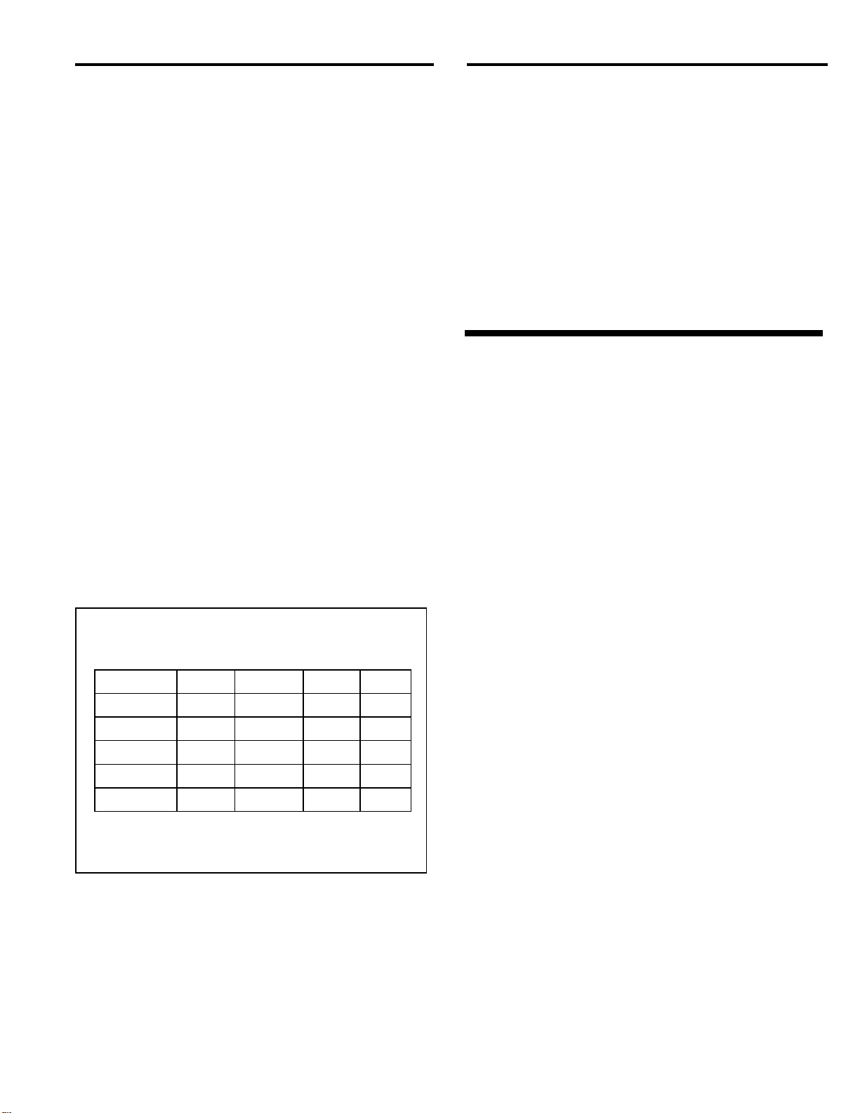
MODEL BNP-162 BNP-164 BNP-166
No. of Guns two four six
Max. volume 1 cu. ft. 2 cu. ft. 3 cu. ft.
Max. weight 100 lbs. 200 lbs. 300 lbs.
Reclaimer cfm 300 or 600 600 or 900 900
1.4.3 Reclaimer: The reclaimer is a pull-thru style,
adjustable, cyclone separator, into which air, dust, fines,
and by-products generated by the blasting process are
drawn from cabinet enclosure for separation. The
reclaimer size is determined by the cabinet size; therefore,
reclaimer sizes are not interchangeable. 300 cfm and 600
cfm reclaimers are attached to the back of the cabinet
enclosure; 900 cfm reclaimers are freestanding.
1.4.4 Dust Collector: All dust collectors used with
these tumble cabinets are pull-thru, reverse-pulse type
cartridge collectors. Dust and fines drawn from the
reclaimer are collected on the outer surface of the filter
cartridge. Refer to dust collector options in Section 1.6.
1.4.4.1 Refer to Figure 1 for arrangement of
components with a CDC-1 dust collector. The model
shown is a 164 with a 600 cfm reclaimer. Figure 2
shows a freestanding 900 cfm reclaimer connected to
an RPC-2 reverse-pulse dust collector. The optional
RPH-2 (600 cfm and 900 cfm) is set up the same way as
the RPC, but includes a hopper for additional dust
storage, and empties into a drum. The overall height of
the RPH is approximately 10-feet, 6-inches, and 12-ft
when the top access door is open. An upgraded, RPC or
RPH collector may be added at any time.
1.5 Theory of Operation
1.5.1 Once the components are correctly setup and
parts are loaded into the barrel, the air supply and
exhauster are turned ON and the cabinet door is closed.
The cabinet is readied for operation by setting the timer
on a constant speed control panel or by pulling the
sequence switch on a variable speed control panel.
Starting the timer causes air to flow through the blast
guns. Air moving through the guns draws media into the
blast gun mixing chamber. The media mixes with the air
and propels out the nozzles. As the barrel rotates, the
parts tumble in the blast stream until all parts and
surfaces are uniformly cleaned. Some of the blast media
remains in the barrel to cushion the parts as they tumble.
A portion of the blast media, along with fines, dust, and
by-products generated by blasting, flows through the
adjustable slide gates into the cabinet hopper. These
particles are drawn into the reclaimer for separation.
Lightweight dust and fines are drawn out to the dust
collector. Heavier reusable media fall through the screen
into the reclaimer hopper for reuse. The dust collector
traps dust and fines and discharges clean air. Blasting
automatically stops when the timed cycle is completed.