Zeta Alarm Systems Premier Power Pack EN54-4 User manual

PREMIER POWER PACK INSTRUCTION MANUAL
GLT.MAN-138
Issue: 1.13 27/7/2012 N.R.P.J.
EN54-4 POWER SUPPLY UNIT
INSTRUCTION MANUAL

PREMIER POWER PACK INSTRUCTION MANUAL
GLT.MAN-138 PAGE 1
Issue: 1.13 27/7/2012 N.R.P.J.
CONTENTS
Introduction to the Premier Power Pack PSU..................................................................... 2
Changes to EN54-4 (The Fire Alarm Equipment Power Supply Standard) ......................... 3
Indications........................................................................................................................... 4
LCD .................................................................................................................................. 4
LED External .................................................................................................................... 5
LED Internal..................................................................................................................... 5
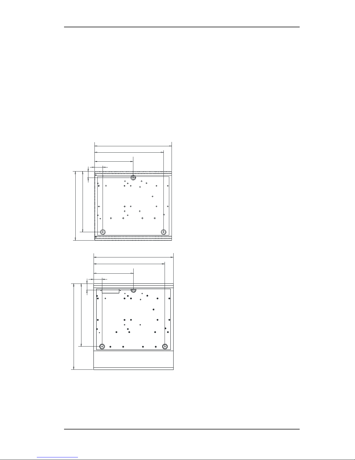
Mounting the Power Supply ............................................................................................... 6
Electrical Connections......................................................................................................... 7
Electrical Safety Measures .............................................................................................. 7
Batteries.......................................................................................................................... 7
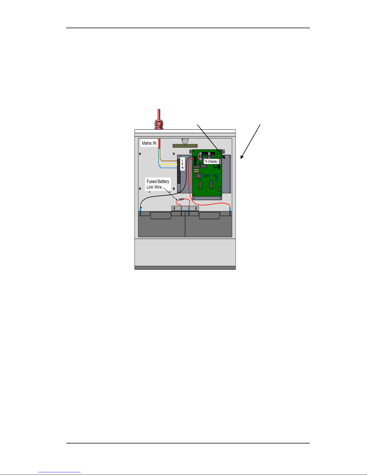
Connecting the Mains & Battery..................................................................................... 8
Connecting Ancillary Equipment to the PSU..................................................................... 10
Recommendations for Cable to Auxiliary Equipment ...................................................... 11
Checking the Battery Charger Voltage.............................................................................. 11
Choosing the Correct Battery Size .................................................................................... 12
Technical Information ....................................................................................................... 13
Maintenance Information................................................................................................. 15
Manufacturer's Declaration.............................................................................................. 15

PREMIER POWER PACK INSTRUCTION MANUAL
GLT.MAN-138 PAGE 2
Issue: 1.13 27/7/2012 N.R.P.J.
INTRODUCTION TO THE PREMIER POWER PACK PSU
The Premier Power Pack is an EN54 compliant Power Supply, intended to power ancillary fire alarm equipment.
It incorporates a small LCD screen that will give information about the Power Supply status (such as output
voltage, output current, charger voltage etc).
It also displays basic information via its LEDs (Power/General fault / earth fault & Battery fault). These LEDs are
located on the panel door, and also on the controller PCB itself.
The power supply has a 3 state charger. It will initially supply a BOOST charge current, until it has detected that
the battery is close to full charge, then it will switch to FLOAT charging. If it detects flat or missing batteries, it will
switch to PULSE mode, until it detects good batteries.
The PSU monitors batteries for High Internal resistance, and will report a fault if it detects a resistance that would
prevent the PSU giving its rated output.
The power supply will prevent battery deep discharge by disconnecting the batteries when they reach their final
voltage under a mains fail condition.
The Power pack PSU is also available as a “CIE version”, used to power fire alarm panels. This version of the PSU is
normally supplied without the current measuring feature.
The “Control panel” version does not have the LCD fitted, so will communicate its status via its internal LEDs only.

PREMIER POWER PACK INSTRUCTION MANUAL
GLT.MAN-138 PAGE 3
Issue: 1.13 27/7/2012 N.R.P.J.
CHANGES TO EN54-4 (THE FIRE ALARM EQUIPMENT POWER
SUPPLY STANDARD)
In 2006 the Fire alarm Power Supply Equipment standard changed, adding the requirement that a PSU should
monitor the internal resistance of its batteries, and give a warning when it is above a certain level.
The reason for this is that when a battery’s internal resistance increases, it will reach a point where the battery
will no longer be able to supply the rated output voltage of the PSU under full load conditions. So under a mains
fail condition, the Power supply, running on batteries only, could not supply it`s rated load.
For Example, if a 5 Amp power supply has batteries with 2 ohms internal resistance, when running on batteries,
and supplying full load, there would be a 10V (V=IxR = 5 x 2 = 10 Volts) drop across the battery, meaning that the
output voltage would be outside the working range of the power supply.
The Premier Power Pack range of power supplies will give a Battery Hi Internal resistance fault when the internal
resistance for that power supply’s rating is close to the level that would cause the working voltage to be out of
range.
NOTE: Batteries reporting a high internal resistance WILL NOT BE CURED BY CHARGING ALONE. Either replace the
batteries, or discharge & charge 3 or 4 times (Note that this will take several days, and is not guaranteed to cure
the problem)

PREMIER POWER PACK INSTRUCTION MANUAL
GLT.MAN-138 PAGE 4
Issue: 1.13 27/7/2012 N.R.P.J.
INDICATIONS
LCD
The Stand alone Premier Power Pack PSU has a 4 line LCD display, which can show the current state of the power
supply.
The Power supply has 2 buttons. The first turns on the backlight. The second will scroll through the available
display screens, showing the PSU`s current state.
Screen 1: PSU Model information and System Normal / Power Supply Fault Indication
Z
E
T
A
A
L
A
R
M
S
Y
S
T
E
M
S
P
R
E
M
I
E
R
P
O
W
E
R
-
P
A
C
K
R
A
T
I
N
G
3
0
V
D
C
5
.
6
A
S
Y
S
T
E
M
N
O
R
M
A
L
This is the model information screen. It will give a general indication of the system state in the bottom line.
System Normal for a healthy system. Power Supply Fault if there are any problems.
Screen 2: Mains / Battery Healthy, PSU output Voltage, PSU output current
M
A
I
N
S
:
O
K
B
A
T
T
S
:
O
K
V
(
A
)
=
2
9
.
5
V
(
B
)
=
2
9
.
5
V
C
U
R
R
E
N
T
0
.
1
2
A
M
P
S
This screen shows whether mains and battery are OK or BAD. It also shows the output voltage, and the current
being supplied. In the event of a blown 24V output fuse, the screen will show V(A)=BAD or V(B)=BAD.
Screen 3: Battery Charger Info
B
A
T
T
E
R
Y
I
M
P
:
0
.
0
0
3
7
C
H
A
R
G
E
R
V
O
L
T
:
2
5
.
4
5
V
C
H
A
R
G
E
T
Y
P
E
:
B
O
O
S
T
B
A
T
T
E
R
Y
S
T
A
T
E
:
G
O
O
D
This screen gives information about the battery & charger circuit. The Battery IMP(edance) is the internal
resistance of the battery , explained in the recent changes to EN 54-4 section.
The Charger Voltage will be the voltage at the battery terminals.
The Charge Type gives the current charging method. The methods used are:-
BOOST –Constant current charge of 920mA. Used when batteries are flat
FLOAT –Float charge is applied as the batteries approach a full charge
PULSE –used when the voltage at the charger terminals is less than the final voltage. Used to check if the
batteries are present.
OFF –Charger is turned off when no mains is present
This manual suits for next models
1
Table of contents
Other Zeta Alarm Systems Power Supply manuals
Popular Power Supply manuals by other brands

Videx
Videx 520MR Installation instruction

Poppstar
Poppstar 1008821 Instructions for use

TDK-Lambda
TDK-Lambda LZS-A1000-3 Installation, operation and maintenance manual

TDK-Lambda
TDK-Lambda 500A instruction manual

Calira
Calira EVS 17/07-DS/IU operating instructions

Monacor
Monacor PS-12CCD instruction manual