manuals.online logo
Brands
  1. Home
  2. •
  3. Brands
  4. •
  5. Zeta
  6. •
  7. Smoke Alarm
  8. •
  9. Zeta ZT-MSH User manual

Zeta ZT-MSH User manual

User manual
ZT-MSH AC/DC smoke & heat alarm
Approved to EN 14604:2005/AC:2008
and BS5446-2:2003
Model CE LPCB Interconnection
Suitable for
Leisure
Accommodation
Vehicles (LAV)
ZT-MSH 2831-CPR-
F2800 330v/01 Yes Yes
Cautions
ELECTRICAL HAZARD: Disconnect power from equipment prior to making any
internal adjustments. Installation and service should only be performed by qualified
personnel.
PRODUCT LIMITATIONS: This smoke & heat alarm does not detect gas, or flame,
and should not be covered with a guard or similar obstructing item.
This smoke & heat alarm may not alert people who are hearing impaired. It is strongly
recommended that the special-purpose smoke & heat alarms using visual or vibrating alerting
devices, should be installed for these occupants.
This smoke & heat alarm may not be effective in fires where smoke and heat is prevented
from reaching the device (eg where intermediate doors are closed), where the fire grows so
rapidly that the egress path is blocked (even when correctly located), and where the fire is
intimate to a person (eg where a victim's clothes catch fire).
SLEEPING OCCUPANTS: Studies have shown that smoke & heat alarms may not
awaken all sleeping occupants, and it is the responsibility of individuals in the
household that are capable of assisting other to provide assistance to those who may be
awakened by the alarm sound, or to those who may be incapable of safely evacuating the
area unassisted.
INSTALLATION LIMITATIONS This product is designed for use in a single
residential unit, such as a family home or apartment. It should only be used in
lobbies, hallways, basements etc. if interconnected with other compatible smoke or heat
alarms. Smoke alarms, located outside the dwelling may not provide early warning to
occupants.
This product is not designed for use in non-residential buildings. Non-residential buildings
require special fire detection and alarm systems. This product alone is not a suitable
substitute for a fire detection system installed in places of work or where people sleep on a
temporary basis, such as hotels or motels, dormitories, hospitals, nursing homes or group
homes of any kind, even if they were once dwellings. Please refer to local regulations for fire
detection and alarm system requirements.
Features
ZT-MSH AC/DC smoke & heat alarms provide smoke/heat detection and
alarm functions within a single unit. Advanced electronics in conjunction with
a photoelectric smoke sensing chamber and an electronic thermistor provide
early detection of smoke and high immunity against unwanted alarms. The
heat sensor provides sensitive rate-of-rise operation or fixed-temperature
operation when the response threshold value is exceeded.
ZT-MSH AC/DC smoke & heat alarms are mains powered, with battery backup,
suitable for general residential applications. ZT-MSH AC/DC smoke & heat
alarms is suitable for general application in residential area and also for
detection of fire without smoke (e.g. ethanol fire). It provides home owners and
installers with an easy-to-install, premium solution for life safety and property
protection applications.
Audible and Visual Alarm Indicators
When operating normally, a green LED in the Test button illuminate. When
smoke/heat is detected, an internal sounder will activate to alert occupants,
and a red LED will flash rapidly. The sounder is a loud, pulsating alarm.
Whenever alarm indication is given, it shall be assumed that is an actual fire.
Test Button
Pressing and holding the Test button for 3 s will activate the smoke & heat
alarm to check its operation. The alarm will sound and the red LED will flash
rapidly. Releasing the test button will return the unit to normal operation.
Low Battery
When the battery is depleted, the smoke & heat alarm will emit a short audible
signal every 48 s for at least 30 days, while the red LED flashes simultaneously.
When the Low Battery signal is given, change the battery without delay.
Fault
When the smoke chamber is degraded or contaminated over a limit or the
thermistor is damaged, the smoke & heat alarm will emit two short audible
signals every 48 s, while the red LED not flashes simultaneously. When the fault
is given, try vacuum the product on the outer surface, especially the smoke inlet,
to remove dirt. If the condition persists, return the product for service.
Hush Button
Pressing the Hush button will reduce the sensitivity of the smoke & heat alarm
for approximately 10 min. The Hush button should only be used after the cause
of the alarm is known (such as normal cooking fumes). The Hush feature
allows time for the smoke/heat to clear. During the hush time, the red LED will
flash once every 6 s. After the Hush time has expired, the smoke & heat alarm
will return to normal sensitivity. If smoke/heat is still present in the unit, the
alarm will re-activate. The Hush feature can be used repeatedly.
Under hush mode, press the hush button again will return the unit to normal
operation.
Alarm Memory
Alarm Memory feature allows easy identification of any unit that has previously
been in the Alarm condition. If a unit enters the Alarm condition and
subsequently returns to the Normal condition, the Alarm Memory is set. Initially,
the red LED will flash three times every 48 s. In order to preserve battery
power, this visual indication will stop after 24 hours and the unit will return to
normal operation.
If the Alarm Memory is active, pressing and releasing the Test/Hush button
resets the Alarm Memory with 3 short beeps.
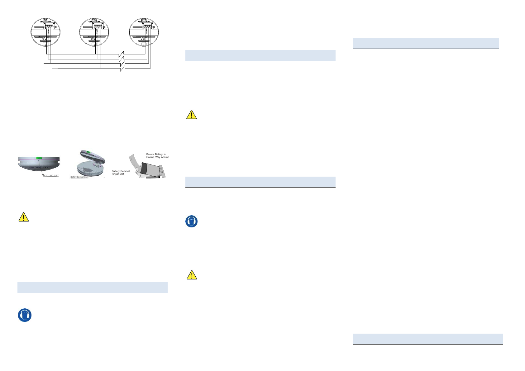
Interconnection Terminals
Interconnected smoke & heat alarms will activate sounders on all units if any
smoke & heat alarm detects smoke/heat. In this case, only the smoke & heat
alarm(s) that detected smoke/heat will flash the red LED indicator. This allows
the home owner to quickly locate the cause of the alarm. Up to 24 units can be
interconnected as long as the cabling is less than 250 m in length.
Specifications
Main power source AC 220 V ~ AC 240 V, 50 Hz
Standby power source DC 9 V battery
Operating temperature 0 °C ~ +45 °C
Operating humidity 10 % ~ 90 % RH, non-condensing
Alarm sounder output ≥85 dB @ 3 m
Interconnection (max) 24 units, 250 m cabling
Approvals
ZT-MSH AC/DC smoke & heat alarms have the following approvals.
EN 14604:2005/AC:2008 Smoke alarm devices
BS5446-2:2008Fire detection and fire alarm devices for dwellings – Part 2:
Specification for heat alarms
CE 2831-CPR-F2800
Installation Preparation
Equipment
Before commencing installation, ensure all equipment and tools to mount and
test the device are available, such as drills, mounting screws (supplied), cables
and ladders.
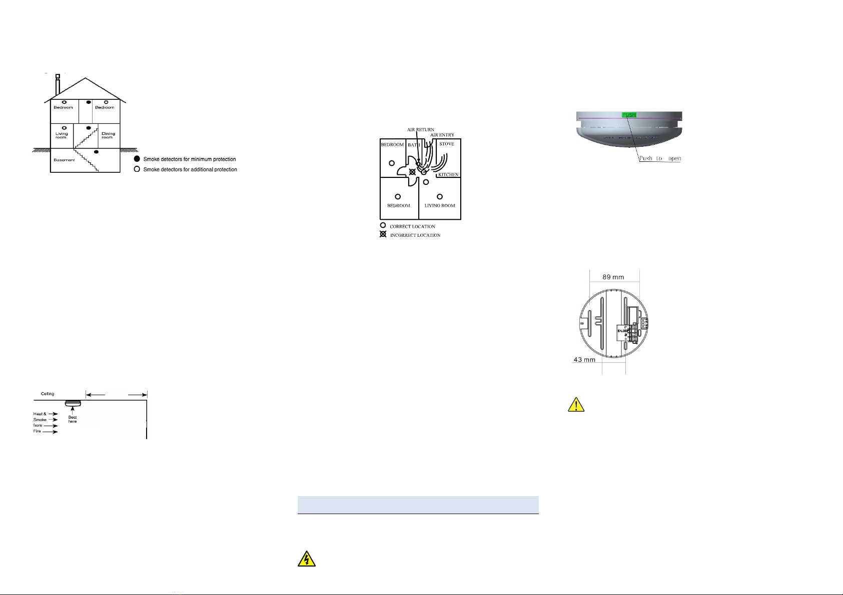
Location Selection in Homes and Apartments
WARNING: Location and number of smoke and heat alarms may be
specified in relevant regulations. Where these do not exist, the
requirements for smoke alarm installation of NFPA 72 can be used. For your
information, the National Fire Alarm Code, NFPA, reads as follows.
11.5.1 *Required Detection.
*Where required by applicable laws, codes, or standards for a specific type of occupancy,
approved single- and multiple-station smoke alarms shall be installed as follows:
(1) *In all sleeping rooms and guest rooms
(2) *Outside of each separate dwelling unit sleeping area, within 6.4 m (21 ft.) of any door
to a sleeping room, the distance measured along a path of travel
(3) On every level of a dwelling unit, including basements
(4) On every level of a residential board and care occupancy (small facility), including
basements and excluding crawl spaces and unfinished attics
(5) *In the living area(s) of a guest suite
(6) In the living area(s) of a residential board and care occupancy
For complete coverage, smoke alarms should be installed in all rooms, halls,
storage areas, basements, and attics in the dwelling. The minimum coverage
is one smoke alarm on each floor and one outside each sleeping area. Please
use the following location guide.
Single Storey Dwellings
Install a smoke alarm in the hallway outside every separate bedroom area, as
shown in Fig. 1 a). Two smoke alarms should be installed in dwellings with two
bedroom areas, as shown in Fig. 1 b).
GLT-317-DoP-2
330v/01
19
2831
Fig. 1 a)
–
Single bedroom area Fig. 1 b)
–
Multiple bedroom areas
Multi-Storey Dwellings
Install a smoke alarm on every floor of a multi-floor dwelling, as shown in
Fig. 2.
Fig. 2 – Multi-storey dwelling
Enhanced Safety
To improve early detection performance and safe evacuation, consider
installing additional smoke alarms as follows.
•At least of two smoke alarms.
•Inside every bedroom.
•At both ends of a bedroom hallway if the hallway is more than 12 m.
•Inside every room where one sleeps with the door partly or completely
closed, since smoke could be blocked by the closed door, and a hallway
alarm may not wake up the sleeper if the door is closed.
•At the bottom of the basement stairwell.
•Second-floor smoke alarms at the top of the first-to-second floor
stairwell.
•In your living room, dining room, family room, attic, utility and storage
rooms.
Be sure no door or other obstruction blocks the smoke path to the smoke
alarm.
Installation Location
Install smoke & heat alarms as close to the centre of the ceiling as possible,
away from light fittings and air-conditioning ducts. If this is not practical, put the
alarm on the ceiling, no closer than 50 cm from any wall or corner as shown in
Fig. 3.
Fig. 3 – Smoke & heat alarm location
from walls
Under flat horizontal ceilings, the horizontal distance from any point in the
protected area to the detector nearest to that point should not exceed 5.3m for
heat detectors
If some of your rooms have sloped, peaked, or gabled ceilings, try to mount
alarms 0.9 m measured horizontally from the highest point of the ceiling.
Where Not to Install Your Smoke & heat alarm
Nuisance alarms occur when smoke & heat alarms are installed where they
will not work properly. To avoid nuisance alarms, do not install smoke & heat
alarms in the following situations.
•In or near areas where combustion particles are present, such as
kitchens with few windows or poor ventilation, garages where there may
be vehicle exhaust, near furnaces, combustion heaters, and space
heaters. Combustion particles are the by-products of something that is
burning, which the smoke & heat alarm may detect.
•Within 6 m of kitchens where combustion particles are normally present.
If a 6 m distance is not possible, e.g. in a mobile home, try to install the
smoke & heat alarm as far away from the combustion particles as
possible, preferably on the wall. Ensure the area is well ventilated.
•In dead-air areas, where ventilation systems cause air-flow that would
not pass through the smoke & heat alarm sensing chamber. Avoid also
air-flow from areas where normal combustion particles are expected,
such as kitchens. Fig. 4, which indicates the correct and incorrect smoke
& heat alarm locations.
Fig. 4 – Dead-air areas
•In damp or very humid areas, or within 3 m of bathrooms with showers.
Moisture in humid air can enter the sensing chamber, then condense into
droplets upon cooling, which can cause nuisance alarms.
•In very cold or very hot areas, including unheated buildings or outdoor
rooms. If the temperature rises above or falls below the operating range
of smoke & heat alarm, it may not function properly. The temperature
range for your smoke & heat alarm is 0 °C ~ 45 °C.
•In very dusty or dirty areas. Dirt and dust can build up on the smoke &
heat alarm’s sensing chamber, to make it overly sensitive. Additionally,
dust or dirt can block openings to the sensing chamber and limit the
smoke & heat alarm from sensing smoke.
•Near fresh air vents or high draft areas like air conditioners, heaters or
fans, fresh air vents and drafts, which can drive smoke away from smoke
& heat alarms.
•In dead air spaces, which are often at the top of a peaked roof or in apex
of ceilings and walls. Dead air may prevent smoke from reaching a
smoke & heat alarm. See Fig. 3 and 4 for recommended mounting
locations.
•In insect-infested areas. If insects enter a smoke & heat alarm’s sensing
chamber, they may cause a nuisance alarm. Where insects are a
problem, get rid of them before installing the smoke & heat alarm.
•Near fluorescent lights. Electrical “noise” from fluorescent lights may
cause nuisance alarms. Do not install smoke & heat alarms within 1.5 m
of such lights.
In the above locations, a heat alarm could be installed as additional protection.
Also the product shall not be contaminated by paint.
Installation and Test
Please read the previous section Installation Preparation, before
commencing installation.
Installing the Smoke & heat alarm Mains and Interconnection
Wiring
WARNING: To avoid the electrical shock hazard, turn off power to the area
where you plan to install the alarm at the fuse box or circuit breaker box.
WARNING: Connect the smoke & heat alarm to a continuous source of mains
power. Ensure the mains power cannot be inadvertently switched off.
It’s recommended that the supply and interconnection wiring to be installed in
accordance with BS 7671.
1. Unhinged the smoke & heat alarm from the base by pressing the PUSH
button located on the side of the base part (see Fig. 5).
Fig. 5 – Press PUSH to unhinge base
2. Place the bracket on the ceiling and mark drill hole locations through the
slots available in the base.
3. Remove the smoke & heat alarm from the ceiling.
4. Drill two 5 mm (3/16-inch) holes at the marks and insert the plastic
mounting plugs (supplied), or other mounting solution (depending on the
ceiling type).
5. Run the mains wiring. Use wiring with conductors of 1 mm2~ 2.5 mm2
cross-sectional area. Wiring should have an insulation resistance of at
least 300 V.
6. Open the terminal cover to access the terminal screws and install the
wiring as shown in Fig. 6.
Key
L AC 230 V mains live/active
E/LOOP Earth or loop
N Neutral / interconnection common
I Interconnection
Fig. 6 – Mains wiring terminals and mounting slots
7. Where interconnection to other ZT-MSH AC/DC smoke & heat alarms is
used, install the interconnection wiring as shown in Fig. 7.
WARNING: Take care to ensure the insulation does not get clamped by
the terminal contact.
WARNING: Do not connect this smoke and heat alarm to any device other
than another ZT-MS smoke alarm, ZT-MH heat alarm or ZT-MSH smoke and
heat alarm. Connecting anything else to this smoke and heat alarm may
prevent it from working properly.
WARNING: To avoid the electrical shock hazard, do not use old wiring that
may have been used for mains voltages. Use wiring with conductors of 1 mm2
~ 2.5 mm2cross-sectional area. Wiring should have an insulation resistance of
at least AC 300 V.
50cm min.
Fig. 7 – Interconnect wiring
Up to 24 ZT-MSH smoke & heat alarms can be interconnected, with a
maximum cable length of 250 m.
8. After all wiring is installed, close the terminal cover.
9. Insert the ceiling plugs and attach the bracket to the ceiling with the
screws supplied.
Installing the Battery
NOTE: The battery is purposefully reversed during production to keep it fresh
until installation.
1. Remove the battery (supplied) from the battery compartment on the
underside of the smoke & heat alarm (see Fig. 8). And correctly fit it in
the battery compartment.
Fig. 8 – Fitting the battery
NOTE:
1) The battery will snap into place and should not shake loose.
2) The battery is polarity-dependent. Ensure it is inserted in the correct
orientation.
WARNING: If the battery is not installed, the battery compartment will
not close and the smoke & heat alarm will continually sound a Battery
Missing signal.
NOTE: When the smoke & heat alarm battery is first contacted, the alarm
sounder may sound for 1 s. This is normal and indicates that the battery is
positioned properly.
2. Close the smoke & heat alarm and mounting base.
3. Connect the mains power.
4. Check that the green LED turns on and red LED in the Test button
flashes every 48 s.
Tests
1. Press and hold the Test button for 3 s to check the smoke & heat alarm
audible warning operates and the red LED flashes rapidly.
WARNING: The smoke & heat alarm has a loud alarm signal. Use
hearing protection when testing smoke & heat alarms.
1. For interconnected smoke & heat alarms, press and hold the Test button
for 3 s on each smoke & heat alarm, and check the smoke & heat alarm
sounder operates on all interconnected smoke & heat alarms.
2. Check that the red LED in the Test button operates only on the smoke &
heat alarm being tested.
NOTE: Smoke & heat alarms should be interconnected within only one family
residence. Otherwise, you might encounter nuisance alarms when a smoke &
heat alarm is operated or tested in another residence.
Normal Operation
Once installed and tested, your smoke & heat alarm will immediately start
monitoring for smoke/heat. If the sounder in the smoke & heat alarm operates,
check for a fire and execute your safety plan.
If the alarm was caused by a nuisance situation, open a window or fan the air
to remove the smoke or dust from within the smoke & heat alarm. The alarm
will turn off as soon as the air is completely clear. Do not disconnect the mains
power and battery to silence the smoke & heat alarm.
Hush WARNING: Before using the Hush feature, identify the source of
smoke/heat and be certain that safe conditions exist.
If investigation of the alarm signal is likely caused by a known nuisance source
(such as cooking fumes/steam), the Hush button can be pressed to silence the
smoke & heat alarm for 10 min. Press the Hush button again will return the unit
to normal operation.
The red LED on smoke & heat alarm will flash once every 6 s while in the Hush
condition.
After the Hush time has expired, the smoke & heat alarm will return to normal
sensitivity. If smoke is still present, the alarm will re-activate. The Hush feature
can be used repeatedly.
Care and Maintenance
Weekly Tests
1. Press and hold the Test button for 3 s on each smoke & heat alarm.
2. Check the smoke & heat alarm sounder operates with a loud pulsating
sound, and the red LED in the Test button flashes rapidly.
WARNING: The smoke & heat alarm has a loud alarm signal. Use
hearing protection when testing smoke & heat alarms.
3. For interconnected smoke & heat alarms, check the smoke & heat alarm
sounder operates with a loud pulsating sound on all interconnected
smoke & heat alarms and the red LED in the Test button operates only
on the smoke & heat alarm being tested. Repeat the test on all
interconnected smoke & heat alarms.
The alarm shall also be tested when back from a long away/vacation from
the house.
WARNING: Never use a naked flame of any kind to test your smoke &
heat alarm. You may set fire to and damage the smoke & heat alarm,
as well as your home. The built-in Test button accurately tests all
alarm functions.
Annual Maintenance
1. Vacuum or carefully wipe the cover of the smoke & heat alarm to remove
any dust, lint or dirt around the openings of the smoke & heat alarm. Do
not spray aerosols into the smoke & heat alarm.
2. After annual maintenance, test all smoke & heat alarms.
Low Battery Alert
When the battery becomes depleted, the smoke & heat alarm will signal a
short beep every 48 s. Immediately replace the battery with an approved
model (see the section User Replaceable Parts).
NOTE: Batteries supply a lower voltage in cold conditions, so the Low Battery
signal may start operating late at night. To avoid annoyance, keep a spare
battery on hand. The Low Battery signal will operate for at least 30 days.
Protection From Fire
Installing smoke & heat alarms is only one step in protecting your family from
fires. You should also reduce the chances that fires will start in your home and
you must increase your chances of escaping safely if one does start. The
following information will help you develop a fire safety program.
1. Install smoke & heat alarms properly. Carefully follow all the instructions
in this manual. Keep your smoke & heat alarms clean, and test them
every week.
2. Non-working smoke & heat alarms will not alert you. Replace your
smoke & heat alarms immediately if they are not working properly.
3. Follow fire safety rules, and prevent hazardous situations:
•Use smoking materials properly. Never smoke in bed.
•Keep matches and cigarette lighters away from children.
•Store flammable materials in proper containers. Never use them
near open flames or sparks.
•Keep electrical appliances in good condition. Do not overload
electrical circuits.
•Keep stoves, fireplaces, chimneys, and barbecue grills grease free.
Make sure they are properly installed and away from any
combustible materials.
•Keep portable heaters and open flames such as candles away
from combustible materials.
•Do not allow rubbish to accumulate.
•Keep a supply of extra batteries on hand for your battery powered
smoke & heat alarms.
Prepare and practice a family escape plan. Review the following with your
children each time you have fire escape drills. This will help everyone
remember them in case of a real fire emergency.
1. Don’t panic and stay calm. Your safe escape may depend on thinking
clearly and remembering what you have practiced.
2. Get out of the house as quickly as possible. Follow a planned escape
route. Do not stop to collect anything or to get dressed.
3. Feel the doors to see if they are hot. If they are not, open them carefully.
Do not open a door if it is hot. Use an alternate escape route.
4. Stay close to the floor. Smoke and hot gases rise.
5. Cover your nose and mouth with a wet or damp cloth. Take short,
shallow breaths.
6. Keep doors and windows closed. Open them only if you have to in order
to escape.
7. Meet at your planned meeting place after leaving the house.
8. Call the Fire Service as soon as possible from outside your house. Give
the address and your name.
9. Never go back inside a burning building.
10. Contact your local Fire Service. They will give you more ideas about how
to make your home safer from fires and how to plan your family’s
escape.
User Replaceable Parts
Blue
Live/Active
Brown
Inter-connecled
Neutral
Earth Loop
The following batteries are replaceable by the user, and may be purchased
from general hardware stores. Use only the specified batteries. Test the alarm
for correct operation using the test facility, whenever the battery is
replaced.
Alkaline:Gold Peak GN1604A, Pairdeer 6LR61
Carbon zinc: Gold Peak 1604S. Pairdeer 6F22
Lithium: EVE CR9V/P
WARNING: When using lithium battery, there is a danger of
explosion if the battery is incorrectly replaced. Replace only with the
same or equivalent type.
References
Document Description
31-0163 ZT-MSH AC/DC smoke & heat alarm datasheet
NFPA 72 National Fire Alarm Code, National Fire Protection Association,
Inc. Quincy, MA 02269, USA
Disposal
Smoke & heat alarms or depleted batteries should not be disposed
of as land-fill. Please dispose in an environmentally friendly manner.
Limited Warranty
NOTE: In order to protect your rights, please keep the original purchase receipt
for the proof of purchase of this Zeta smoke & heat alarm from our authorized
dealers. No warranty can be offered without the original purchase receipt.
Zeta warrants its enclosed Smoke & heat alarm - but not the battery - to be free from
defects in materials and workmanship under normal use and service for a period of five
years from date of purchase. Zeta makes no other express warranty for this Smoke &
heat alarm. No agent, representative, dealer, or employee of Zeta has the authority to
increase or alter the obligations or limitations of this Warranty. Zeta's obligation of this
Warranty shall be limited to the repair or replacement of any part of the Smoke & heat
alarm which is found to be defective in materials or workmanship under normal use and
service during the five-year period, commencing from the date of purchase.
During the initial one-year period, commencing from the date of purchase, such repair or
replacement shall be made without charge. During the latter four years of the Warranty
period, such repair or replacement shall be made at a charge to the Customer, not to
exceed the manufacturer’s cost. Units in need of repair should be returned, shipping
prepaid, to ZETA ALARMS LIMITED, DETECTION HOUSE, 72-78 MORFA ROAD,
SWANSEA, SA1 2EN, UNITED KINGDOM.
Zeta shall not be obligated to repair or replace units, which are found to be in need of
repair because of damage, unreasonable use, modifications, or alterations occurring after
the date of purchase. The duration of any implied Warranty, including that of
merchantability or fitness for any particular purpose, shall be limited to the period of five
years commencing with the date of purchase. In no case shall Zeta be liable for any
consequential or incidental damages for breach of this or any other Warranty expressed
or implied whatsoever, even if the loss or damage is caused by Zeta's negligence or fault.
Some states do not allow the exclusion or limitation of incidental or consequential
damages, so the above limitation or exclusion may not apply to you. Zeta makes no
warranty, expressed or implied, written or oral, including that of merchantability or fitness
for any particular purpose, with respect to the batteries. This Warranty gives you specific
legal rights, and you may also have other rights which vary from state to state.
View the complete range of products at
www.Zetaalarmsystems.com
Zeta Alarms Limited,
72-78 Morfa Road,
Swansea, SA1, 2EN
United Kingdom
© 2019 Zeta Alarms Limited. All rights
reserved. All specifications and other
information shown were current at the date
of publication and subject to change without
notice.
33-0103-r03_2020-10

Other Zeta Smoke Alarm manuals

Zeta ZD-SI-610/ZD-SO-610 User manual

Zeta

Zeta ZD-SI-610/ZD-SO-610 User manual

Zeta ZT-MS User manual

Zeta

Zeta ZT-MS User manual

Zeta ZD-SI-601/ZD-SO-601 User manual

Zeta

Zeta ZD-SI-601/ZD-SO-601 User manual

Zeta NPAD 2 Product guide

Zeta

Zeta NPAD 2 Product guide

Popular Smoke Alarm manuals by other brands

SANJIANG A9036T manual

SANJIANG

SANJIANG A9036T manual

Swegon TBLZ-1-87-a Installation

Swegon

Swegon TBLZ-1-87-a Installation

First Alert SCO500NVA Specification sheet

First Alert

First Alert SCO500NVA Specification sheet

First Alert SA300 user manual

First Alert

First Alert SA300 user manual

SAFE-T-ALERT SA-775 quick start guide

SAFE-T-ALERT

SAFE-T-ALERT SA-775 quick start guide

LST AO-58000-600 Specification sheet

LST

LST AO-58000-600 Specification sheet

Bosch RADION RFSM-A installation guide

Bosch

Bosch RADION RFSM-A installation guide

Orientalert VST-IS5981 user manual

Orientalert

Orientalert VST-IS5981 user manual

System Sensor 2WTR-B Installation and maintenance instructions

System Sensor

System Sensor 2WTR-B Installation and maintenance instructions

x-sense XS03 user manual

x-sense

x-sense XS03 user manual

Holtek HT45F24A quick start guide

Holtek

Holtek HT45F24A quick start guide

Yale EF-SD instruction manual

Yale

Yale EF-SD instruction manual

Elk Products ELK-6050 installation instructions

Elk Products

Elk Products ELK-6050 installation instructions

FlameStop VESDA-E VEP-A00-1P Product guide

FlameStop

FlameStop VESDA-E VEP-A00-1P Product guide

Xtralis Xtralis ICAM ILS-1 Product guide

Xtralis

Xtralis Xtralis ICAM ILS-1 Product guide

ThermoWorks Smoke Receiver operating instructions

ThermoWorks

ThermoWorks Smoke Receiver operating instructions

Robotronics Buzz E operating manual

Robotronics

Robotronics Buzz E operating manual

American Sensor SA360 user manual

American Sensor

American Sensor SA360 user manual

manuals.online logo
manuals.online logoBrands
  • About & Mission
  • Contact us
  • Privacy Policy
  • Terms and Conditions

Copyright 2025 Manuals.Online. All Rights Reserved.