ZEZ SILKO PFR 6 User manual

controller
PFR 6
/
PFR 12
POWER FACTOR REGULATOR Controller
PFR 6/ PFR 12
The Controller
PFR 6
/
PFR 12
PF regulators measure cosϕin a supply system and control the connection and disconnection of capacitors to
obtain a target programmed value.
This manual is an easy guide for the use and operation of the
Controller
PFR 6
/
PFR 12
. For more information, the complete
manual can be downloaded from the web site of ZEZ SILKO
:
www.zez-silko.cz
Any manipulation or use of the equipment out of the conditions
specified by the manufacturer may put in risk the user safety. Before
any maintenance operation the equipment must be disconnected from power
supply. In case of miss operation or protection fault the equipment must be
disconnected from supply and remain out of service ensuring against any
accidental reconnection.
1.- Regulator Connection
For proper operation it’s necessary to install a current transformer, CT
(normally In / 5 A), which primary must be sized according to the
maximum expected load current in the installation.
The regulator supply (C-D terminals) must
be taken between two
phases and the CT should be located in the third phase. See technical
characteristics for cable sizes and required protections.
Must use an switch or automatic switch for supply the regulator
COM
7
8
9
10
11
12
COM
L2
1
2
3
4
5
6
L3
A
B
S1
S2
C
D
RELAY C1..C6
RELAY C7..C12
Sólo en
Computer
max
12
POWER
SUPPLY
The current
transformer , CT,
must be located so that it
measures the whole load current
plus the correction capacitors
CT S1
S2
CAPACITORS
2.- TECHNICAL CHARACTERISTICS
Supply and V measurement input
terminals (C-D)
400 VAC - standard, 110, 230, 480 VAC-on request, +15%-10%
45-65 Hz, Connect preferably to phases L2-L3
Supply cables size and protection Cross section 1,5mm2; 0,5 to 2A Fuses gl type
Current measurement circuit
Current transformer (CT) , In /5 , Place preferably in phase L1
Minimum cabling cross section 2,5mm2
Current measurement margin 0,1 to 5 A (maximum overload +20%)
Accuracy of measurements
Voltage and current :1%; cosϕ:2% ±1 dígit
Power consumptions
110V: 7 VA (no load) ; 8 VA(6 relays); 9,8 VA(12 relays)
230V: 7 VA (no load) ; 8 VA(6 relays); 9,6 VA(12 relays)
400V: 6 VA (no load) ; 7,5 VA(6 relays); 9,5 VA(12 relays)
480V: 7,8 VA (no load) ; 8,6 VA(6 relays); 10 VA(12 relays)
Display
1 line x 3 digits x 7segments + 20 icons
Output Relay Contacts Max. 250 VAC, 10 A, AC1
Output Relay Cabling and
Protection Cabling cross section 1,5mm2, Protection by means of a 6A
circuit breaker (C curve) or by a 6A fuse (gl type)
Alarm Output Relay Last relay automatically set as alarm output , if not in use
Compliant to the following
Standards
EN61010, EN61000-3-2,EN 61000-3-3,EN 50081-2,EN 50082-
1, EN 50082-2, EN 61000-4-2,EN 61000-4-4,EN 61000-4-8, EN
61000-4-5,EN 61000-4-11, UL 94
Safety / Insulation Category III , Class II, According to EN 61010-1,
Environment limit conditions
Temperature limits: -20ºC a +60ºC; Relative Humidity 95%
(without condensation). Max. Altitude: 2000m
Protection degree IP51 (panel mounted)
IP30 (regulator box) , According to EN-60529
Control system
FCP (Minimum number of operations)
3.- Four Quadrants Operation
The Controller
PFR 6
/
PFR 12
regulators operate in 4 quadrants (suitable
for imported or exported active power). For exported power, a negative
symbol is displayed in the cosϕindication. Check phase connection and
setup if there is no exported energy and the indication is not correct (see 4.3,
SET-UP - phase)
0º
90º
180º
-90º
Imported Power
Exported Power
KW +
kVAr +
Leading/Capacitive
KW -
kVAr - KW +
kVAr -
Lagging / Inductive
KW -
kVAr +
Cosϕ-
Lagging / Inductive
Cosϕ-
Cosϕ+
Cosϕ+
Leading/Capacitive
Display
Standard mode: Displays cosϕ
cosϕIndication / setting
C/Ksetting.See paragraph6
Program setting.See 4.2
Delay time setting for switching on/off operations
Nr of steps setting
Setting CT phase and polarity connection
- Cursorkeys(when in setting mode)
- ManualON / OFF (push during more than1s when in RUN mode)
- Push both to see the Nr of connected steps
SETUP KEY:Pushduring more than 1s to enterSETUPmode
Lagging current indication (Inductive load)
11
Leading current indication (Capacitive load)

controller
PFR 6
/
PFR 12
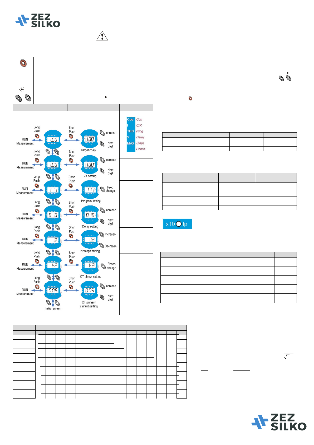
4.- SETUP AND MEASUREMENTS
To enter the SETUP mode, press the setup key (9), for more than 1s. If all the capacitors are disconnected, the access in immediate, otherwise a disconnection sequence
starts and then accesses to setup menu. In the SETUP mode, if no key is pressed for 3 minutes, the equipment exits such mode and returns to normal operation mode.
Key to access the SETUP mode:
- Long push to enter and exit SETUP mode. Also DELETE max values when
in the measuring mode
- Short push: to change from display mode to editmode and vice versa.
If no key ispushed during more than 3 minutes, the regulator exits the SETUP
mode without changing the setup.
:
Symbolshowing whichparameter isbeing displayedor edited.
-In the display mode: Cursors toselect anoption.
pointsto theoption
- In edit mode: Change a parametervalue
Display SETUP Parameters Edit SETUP parameters Description
MENUOPTIONS
Targetcosϕ(def=1)
ReactiveIof1
st
step,
C/Kadjustment
Range: 0.02–1.00
Seeparagraph6
Programsetting
Dependsonthekvar
relationshipbetween
successivesteps.
Seeparagraph 4.2
Delayforsuccessive
steps (4-999s).
Re-connectiondelay
is =5timesTON
SelectionofNrof
relays,PFR6or12
dependingon type
CTconnection. See
paragraph 4.3. The
displayshows T1,T2,
T3,T4,T5orT6.
Accepttheoption
givingcosϕbetween
0.7Ind and0.98Cap
CTprimarycurrent
setting.See
paragraph4.4
4.1.- RUN & Measuring mode
In normal operation mode (RUN mode) the regulator display may show different
parameters (V, I, cosϕ, etc.) The displayed parameter is pointed by the sign .
By default the regulator displays the cosϕ, but pushing the keys the
following parameters can be explored: Current (I), Current harmonics (THD), Mains
Voltage (V), Maximum current (I MAX) y Maximum voltage (V MAX). If both keys
are pushed simultaneously the regulator displays the Nr of connected steps.
A long push of key when maximum values are displayed causes de deletion of
recorded max values.
4.2.- Program selection
This setting depends on the kvar ratio between the different capacitor steps. For
instance if the bank is 10+20+20+20 kvar the program is 1:2:2:2, so the option 122
must be selected.
Display Program Display Program
111
1:1:1:1
248
1:2:4:8
122
1:2:2:2
112
1:1:2:2
124
1:2:4:4
4.3.- Selecting the CT connection phase
Choose among the options in the table depending on CT connection and the
phases where V is measured. In normal installations (no exported energy) choose
the option for which the displayed cosϕis between 0.7 Ind and 0.98 Cap.
Display
V-I phase shift at
cosϕ=1
Measuring phases
for V Phase where TC is
connected
T1
30º
L3-L2
L3
T2
270º
L3-L2
L1
T3
150º
L3-L2
L2
T4
210º
L3-L2
L3 (CT reversed)
T5
90º
L3-L2
L1 (CT reversed)
T6
330º
L3-L2
L2 (CT reversed)
4.4.- Selecting the rated primary current of CT
If the LED is blinking indicates that we are in SETUP mode and
adjusting primary CT current. When in RUN mode or when Iprimary is displayed,
the LED indicates whether the displayed current has a scale factor x1 (LED OFF)
or x10 (LED ON)
5.- Error Codes
ERRCODE DISPLAY DESCRIPCIÓN ACTUACIÓN
E.01 Alll zeros
Load current below measuring threshold or
CT notconnected
Forcesallthe
relaysOFF
E.02 cosϕand E.02
alternate blinking
Overcompensation.Theregulador isaskingto
disconnectCsandtheyareall disconnected
NOACTION
E.03 cosϕand E.03
alternate blinking
Sub-compensation.Theregulatorisaskingformore
Csandthey areallconnected
NOACTION
E.04
cos
ϕ
and E.04
alternate blinking
Overcurrent.Thecurrentis+20%.Aboveprimary
ratedcurrent
NOACTION
E.05
cos
ϕ
and E.05
alternate blinking
Overvoltage.Voltageis +15%.Aboveratedvoltage
NOACTION
6.- C/K table depending on initial cosϕ, desired cosϕand CT ratio
CT Ratio
Lower step reactive power (kvar) at 400V
C/K calculation:
If It is the primary rated current of the CT and
Ic the rated current of the lower capacitor step,
the C/K must be set according to the
calculations shown below:
Example : CT current ratio = 500/5
Lower step power: 60 kvar at 400V
A7,86
40073,1 000.60
I;100
5
500
KC=
×
===
867,0
100
7,86
K
Ic
K/C ===
It K
5
=
V.3
Q
IC=
C K Ic
K
/=
CT 2.5 5,00 7.5 10,0 12,5 15,0 20,0 25,0 30,0 37,5 40,0 50,0 60,0 75,0 80,0
150/5 0,12 0,24 0,36 0,48 0,60 0,72 0,96
200/5 0,09 0,18 0,27 0,36 0,45 0,54 0,72 0,90
250/5 0,07 0,14 0,22 0,29 0,36 0,43 0,58 0,72 0,87
300/5 0,06 0,12 0,18 0,24 0,30 0,36 0,48 0,60 0,72 0,90 0,96
400/5 0,05 0,09 0,14 0,18 0,23 0,24 0,36 0,48 0,58 0,67 0,72 0,87
500/5 0,07 0,11 0,14 0,18 0,22 0,29 0,36 0,45 0,54 0,54 0,72 0,87
600/5 0,06 0,09 0,12 0,15 0,18 0,24 0,30 0,36 0,45 0,48 0,60 0,72 0,90 0,96
800/5 0,07 0,09 0,11 0,14 0,18 0,23 0,27 0,33 0,36 0,45 0,54 0,68 0,72
1000/5 0,05 0,07 0,09 0,11 0,14 0,18 0,22 0,27 0,29 0,36 0,43 0,54 0,57
1500/5 0,05 0,06 0,07 0,10 0,12 0,14 0,18 0,19 0,24 0,29 0,36 0,38
2000/5 0,05 0,07 0,09 0,11 0,13 0,14 0,18 0,22 0,27 0,28
2500/5 0,06 0,07 0,09 0,10 0,12 0,14 0,17 0,22 0,23
3000/5 0,05 0,06 0,07 0,09 0,10 0,12 0,14 0,18 0,19
4000/5 0,05 0,06 0,07 0,09 0,11 0,14 0,14
For different voltages (V) of 400V, table result must be multiply for 400/V, or calculate C/K parameter using the expressions.
7.- Technical Service
For any inquiry about the regulator operation or in case of malfunction please
contact with technical service.
ZEZ SILKO, s.r.o.
Pod Černým lesem 683
56401 Žamberk
Česká republika
tel.: +420 465673111
e-mail: zez@zez-silko.cz
www.zez-silko.cz Nabijte se energií s námi
This manual suits for next models
1
Other ZEZ SILKO Controllers manuals
Popular Controllers manuals by other brands

Johnson Controls
Johnson Controls M9102-AGA-2S Series quick start guide

Mitsubishi Electric
Mitsubishi Electric QX10 user manual

VERDER
VERDER CARBOLITE GERO 3216 Series Installation, operation and maintenance instructions

Nelson
Nelson CM-2201 Installation and operating instructions

eMotionLighting
eMotionLighting EML1205 instruction manual

Aphex
Aphex Compellor 320A owner's manual