Zhone 900 Guide

Zhone Technologies, Inc. @Zhone Way, 7001 Oakport St., Oakland, CA 94621 (510) 777-7000 Fax: (510) 777-7001
Zhone Tech Tip TT#33
February 15, 2011
900 Power Cable Maintenance
This procedure is provided to our customers experiencing intermittent and unexplained
PSU alarms that raise and clear on their own. Please refer to Zhone Field Advisory
bulletin 20071206-2 FAB – IMACS Power Supply OOS Alarm in order to clear these
alarms.
This Tech Tip is written to describe the process used to clean the power cable on the
IMACS-900 shelf. Please refer to Zhone Tech Tip #34 for the proper procedure if
maintenance to clean the power cable is required on an IMACS-600 or IMACS-800 shelf.
The IMACS-900 uses a 18-pin wiring harness to connect the power PCB to the shelf
PCB. The cable is shown in Figure 1.
Figure 1: Power Cable IMACS-900
This procedure is provided to augment the Field Advisory bulletin 20071206-2 FAB –
IMACS Power Supply OOS Alarm. This Tech Tip provides greater detail on the item
under the section for Valid Alarms of that bulletin, and specifically the note that
indicates:
•Bad physical connection on the wiring harness cable due to oxidation or
poor environmental conditions. Remove wiring harness, clean with
degreaser and alcohol solvent, apply NO-OX-ID lubricant and reconnect
wiring harness.
NOTE: This procedure requires that the IMACS be powered-down to perform this
service. Be sure to remove all power sources from the IMACS before beginning this

Zhone Technologies, Inc. @Zhone Way, 7001 Oakport St., Oakland, CA 94621 (510) 777-7000 Fax: (510) 777-7001
procedure. It is also recommended that all jewelry (rings, watches etc.) be removed
prior to working on the IMACS shelf. Failure to use caution before beginning this
procedure could result in shock and / or injury. A properly grounded work area is
required to prevent any damage to the equipment.
Tools Required:
The following tools will be required:
Slotted screwdriver
Phillips screwdriver
Degreaser such as ElectrO-Wash by Chemtronics.
Non-conductive oxidation reducer such as NO-OX-ID
Pair of wire cutters
Two zip ties
Procedure Overview:
This procedure to clean the power supply cable is for the IMACS-900 shelf. It is
suggested that this procedure be performed on any IMACS shelf over ten years old at the
same time as the Interface card battery replacement. To find out more about the Interface
card battery replacement, call your Zhone representative and ask about GSS service
product codes 3021AR and 3021FG. This power cable maintenance procedure can be
done anytime a PSU OOS intermittent alarm condition exists, and should also be
performed as routine maintenance once a shelf reaches ten years old. This procedure
details the location of the cable, the removal and cleaning of the cable and posts, the re-
installation of the cable and confirmation of the IMACS service level at the end of the
procedure.
Power Supply Cable Location:
The following illustrates the location of the Power Supply Cable.

Zhone Technologies, Inc. @Zhone Way, 7001 Oakport St., Oakland, CA 94621 (510) 777-7000 Fax: (510) 777-7001
Figure 2: IMACS-900 Power Cable Location
The Power Supply cable is located on the front of the IMACS-900 and extends between
the top power supply portion of the shelf behind slot F2 and the lower shelf backplane
behind circuit card slot U8.
Note that the brown wire of the cable is oriented to the top of the cable connector.
Cable Removal:
In order to remove the cable, it will be necessary to remove power from the shelf. Prior to
starting, it should be recorded what cards occupy which slots. It is highly recommended
to perform a database backup prior to beginning the procedure (save to flash, save off-
shelf). In order to have room to maneuver, it is recommended that the cards around the
cable connector be removed to allow for plenty of room to work on the shelf.
Procedurally:
1. Back up system image to flash. On the main login screen, enter ‘Y’ for
system. Select ‘B’ for backup, and change ‘PROTOCOL’ from ASCII to

Zhone Technologies, Inc. @Zhone Way, 7001 Oakport St., Oakland, CA 94621 (510) 777-7000 Fax: (510) 777-7001
‘FLASH’ and then enter ‘G’ for GO. If prompted, choose ‘y’ to overwrite the
existing saved copy of nvram.
2. Back up system image off shelf (ASCII, TFTP). If unclear how to perform
this action, please refer to section 4.12.1 Test, Debug, Backup & Restore of
the System Reference Guide for more information.
3. Disconnect all power from the shelf.
4. Remove all jewelry on fingers and wrists, up to the elbow.
5. Remove power supply cover from the front of the shelf.
6. Record circuit pack locations – refer to Table 1.
7. Remove circuit packs around the work area to allow for maneuvering.
8. Remove the power cable.
9. Clean the power cable.
10. Clean the posts.
11. Replace the IF card battery on shelves nine years old or older.
12. Replace the power cable.
13. Replace the circuit packs.
14. Reconnect power to the shelf
15. Validate service.
In order to service the power cable on the IMACS 900, the power block at the upper right hand corner
of the shelf must be removed. Refer to figure 3 below to identify the securing screws which must be
removed in order to service the unit.

Zhone Technologies, Inc. @Zhone Way, 7001 Oakport St., Oakland, CA 94621 (510) 777-7000 Fax: (510) 777-7001
Figure 3: Power Block Screw locations
The removal of the power block will reveal the locations of the tie-wraps which must be
cut in order to allow for the removal of the power cable. Refer to figure 4 below to
identify the locations to cut the tie-wrap holders. Use extreme caution when cutting these
tie-wraps to ensure that the power cable is not accidentally damaged.

Zhone Technologies, Inc. @Zhone Way, 7001 Oakport St., Oakland, CA 94621 (510) 777-7000 Fax: (510) 777-7001
Figure 4: Power Block moved - tie-wrap locations
Once the tie-wraps have been cut and removed, the power cable can then be removed
from the shelf by threading the cable through the slot to the right of location U8.
The cable is held in place by locking edges on the connector and the mating connector
housing. This mechanism is used to securely hold the cable to the motherboard – see
Figure 5 below.

Zhone Technologies, Inc. @Zhone Way, 7001 Oakport St., Oakland, CA 94621 (510) 777-7000 Fax: (510) 777-7001
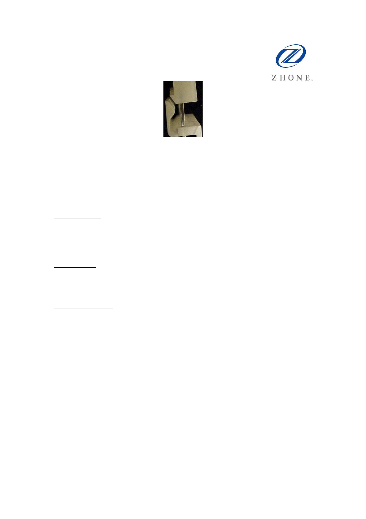
Figure 5: Mate and Lock Connector
This cable will take some force to overcome this connection. Room to maneuver inside of
the IMACS housing will allow for maneuverability. Care should be taken to not break the
lip on the backplane side of the connector, as a ten-tear old connection might become
brittle. Upward force on the cable, or a small wedge (such as a screwdriver tip) inserted
between the two flat surfaces can result in a successful de-coupling of the connector.
Cable Cleaning
Both ends of the cable can be cleaned in turn by using a spray degreaser into the receptor
holes of the cable. The degreaser should mention that it is suitable for use on PC boards.
Once both ends of the cable have been cleaned, then a non-conductive oxidation
preventative can be applied directly into the receptor holes of the cable connector.
Post Cleaning
Similar to the cable ends, the posts on the IMACS backplanes should also be cleaned
with the degreaser used above. A non-conductive oxidation preventative should be
rubbed onto the metal posts to ensure complete coverage and coating.
Cable Replacement
Once the cable and posts have been thoroughly cleaned and coated, the cable can then be
replaced.
When re-installing the cable, ensure that the brown wire is oriented towards the top of the
connector, matching the original.
Be careful to thread the cable through the slot to the right of user card U8, so that the
cable can then be re-fastened to the side wall of the IMACS-900 shelf. The action of
installing the cable onto the posts also provides some abrasive cleansing, so placing the
cable onto the posts and then removing it a few times helps to ensure a more thorough
contact area.
Take care to line up the cable with the posts to ensure all pins are mating with the cable
connector. The cable ends have a lip on them that will mate and lock with the connector
on the board side. Use some force when installing the cable connector to make sure that it
locks into place on the board. If the cable does not lock, make sure it is oriented properly.

Zhone Technologies, Inc. @Zhone Way, 7001 Oakport St., Oakland, CA 94621 (510) 777-7000 Fax: (510) 777-7001
Reconstructing the Unit
Now that the cable has been replaced, the two tie-wraps that were cut in order to remove
the cable need to be replaced. Thread a tie-wrap through the metal holders located on the
side wall of the IMACS-900 shelf as illustrated in Figure 4 above. These cable ties secure
the cable to the shelf, so that they do not interfere with the user card in slot 8, nor with the
power block that has been temporarily moved out of the way.
Once the tie-wraps have been used to secure the cable to the side of the enclosure, the
power block can then be placed back into its original location as illustrated in Figures 2
and 3.
With the power properly routed, the individual cards should be replaced as documented
in Table 1. Care should be taken to properly secure each card into its respective slot in
accordance with the recorded data.
Validation
With all the cards now firmly in place, the unit is ready for power to be applied.
Reconnect the power source to the IMACS shelf, and validate the proper status displayed
on the individual cards, when such status indicators exist. Log into the IMACS shelf, and
validate that the status of each card is correct, and validate services. Once the unit has
been verified, it is once again advised to save a database to an off-site location.
Designator
Card Designator Card
C1 IF
C2 W1
P1 W2
P2 W3
P3 W4
U1 F1
U2 F2
U3 R1
U4 R2
U5 HP1
U6 HP2
U7 NS1
U8 NS2
Table 1: Card Locations
Table of contents
Popular Cables And Connectors manuals by other brands

Bticino
Bticino F441 Instructions for use

Transparent Audio
Transparent Audio The Brick Super owner's manual

FasTest
FasTest 60V Series REPAIR & REBUILD INSTRUCTIONS

Philips
Philips SJM3110 Specification sheet

Tyco Electronics
Tyco Electronics SOLARLOK 4-1394462-6 installation manual

LINK-MI
LINK-MI LM-SP142M quick start guide