Zico ZI-9500 User manual

www.zicotech.com
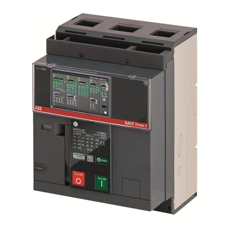
RCD tester
Residual Current Device- circuit breaker

Warnings
Read the documentation and fully assimilate the
information it contains before use
Do not use the appliance on voltages greater than 230
V.inspect the appliance before use. Do not use the
appliance if it is damaged.
If a 400 V pictogram is displayed, disconnect the appliance
immediately and check the installation.
The nature of the test is to trip differential protection
mechanisms. At the end of the test, there is therefore no
power on the tested port of the installation.
Before using the appliance, you must therefore ensure
that the absence of power will not harm any
People or damage equipment (medical,
computers ,industrial plant, etc.).
The tester is not a No Voltage Tester (nvt).
Use an appliance designed for this purpose.
The manufacturer must carry out the after-sales
operations.
Do not attempt to continue the tests if the default voltage
(50V) is displayed (calculated for I-
△n); then check the installation.
Leakage currents in the installation can change the
interpretation of the measurements.
This appliance is fitted with Ni-MH batteries. Comply with
the national waste disposal instruction.
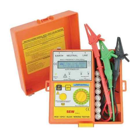
PARTS & CONTROLS
1. Digital Display
2. 0/180 Button
3. Test Button
4. Rotary Function switch
5. N/S & Backlight button

6. Range button
7. POWER Jack
8. Pothook
9. Battery Cover
Differential tester
The main function of the tester is to test and measure the
trip values of RDDS (Residual Differential Devices):
-in trip time (expressed in ms) or
-in trip current value (expressed in mA).
This enables 10mA / 30mA / 100mA/ 300mA / 500mA and
1000mA differential circuit breakers to be tested
irrespective of their type (normal or delayed s).
This comprehensive appliance can also be used to test the
conformity of the network and the connection of the
earthing conductor.
wires state test
Link the test line
Check the wires state:
Before push the “test” button, checks for the following
conditions and indicates the test result on the display.

Wiring Condition Display Indication
N G H
Correct Wiring ● ● ●
No Ground ● ○●
Polarity Reversal ¤ ● ¤
Open/Hot Neutral ○○○
Legend: ●On ○Off ¤ Flashing
If the wiring condition is other than normal, the Test is
limited on its measurements that can be performed. If a
no ground condition exists, only the line voltage
measurements are available.
Notes:
1) Will not detect two hot wires in a circuit.
2) Will not detect a combination of defects.
3) Will not detect reversal of grounded and
grounding conductors.
Voltage test:
Never apply voltages exceeding 300V to input sockets.
Connect mains lead (13) to the mains connector
Select function V via the function switch
Connect the test leads /mains plug to UUT

Read the measurement result on the display
If the voltage exceeds 300V, In this instance, immediately
disconnect the measurement instrument from UUT.
The tester only used in AC230v +10% -15% (50Hz).
Measuring and testing the differentials
Selection of the differential type and measurement type:
Before testing an RDD, you must select the characteristics
on the display (sensitivity, delayed or not) together with
the type of test that you are required to perform (trip time
or current).
You make the selections by pressing the buttons under
each columns. The characteristics are selected one after
the other and are outlined by a rectangle
Comment: The selection can be made with the appliance
unconnected (switch on the appliance in this case) or
connected to the socket (the appliance then switches on
automatically).
1 –Selecting the RDD sensibility:
Use the second navigation button to select the appropriate
sensitivity I△n (assigned current for differential trip):

10mA / 30mA / 100mA/ 300mA / 500mA or 1000mA
2 –Normal/Delayed selection:
Use the right-hand button to choose the RDD type: N
(normal: not delayed) or S* (delayed)* Selectivity rules
require that the RDD’s fitted at the furthest point on in the
installation trip first. S-type RDD’s therefore do not exist in
10 mA or 30mA .The tester does not make this choice
available.
3 –Selecting 0°or 180°
RDDs can react differently depending whether the default
current starts with a positive half-cycle (0°) or a negative
half-cycle(180°). The tester automatically sets itself to a
current starting with a positive half-cycle (0°).If you want
to perform a test that starts with a negative half-cycle, all
you have to do is set the appliance to.
4 . Selecting the type of test (x1/2, x1, x2, x5 current,
Auto or Amp :either in current.
The tester shows the “mA” measurement unit
on the screen.
or in time.
The tester shows the “ms” measurement unit
on the screen.

Note: for each new switch on, the selection is positioning
in the most common test 10 mA/N/0°.
Measurement results
Once the selections have been made, press the TEST
button. The digital result is shown .
Battery Replacement
1. When the low battery symbol” ”appears
on the LCD, the six 1.5V ‘AA’ batteries
must be replaced.
2. Remove the screw holding the battery cover
3. Remove the battery compartment cover
4. Replace the batteries observing polarity
5. Affix the rear cover and secure the screw.
Technical characteristics
- 3-digit measurement display
- N or S (delayed) type RDD test, - AC or A (continuous
component detection)
- Operates ona TT neutral and TN system
- Operating voltage:230V (Ph/N) –10/+6% 50/60 Hz

Measurement
specifications
Ranges
resolution
accuracy
Nominal test
current
10/30/100/500mA/1A
(-2%+10%)+6Digits
Current
selection
0.5 x, 1x, 2x, 5 x
nominal current
Trip time
10-2000 ms at 0.5 x
10-500 ms at 1x
10-150 ms at 2x
10-40 ms at 5x
1ms
±(2%rdg.+2Digits)
Ramp test
0.4 x to 1.4 times
nominal rated current
10 %
Mains voltage
230(+10%/-10%)V
1v
±(2%rdg.+2Digits)
- Cat III 600V
- Double insulation
- IEC 61010-1
- IEC 61557-6 NF EN 61557-6
- IEC 61236 (EMC)
- Locking and warning signals for 400V network voltage
and contact potentail >50V
- Operating temperature: -15°C /+45°C
- Storage temperature: -25°C /+70°C
- IP40
Table of contents