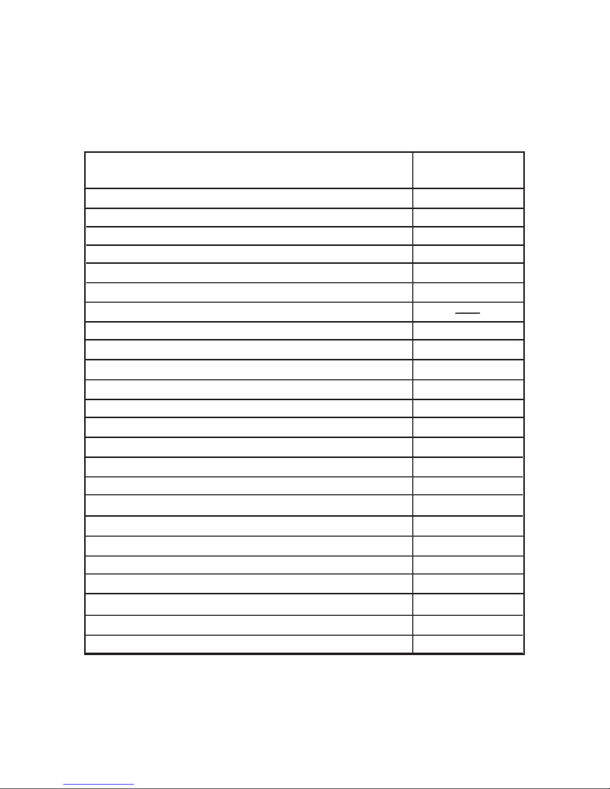
Ziegler mfm 3480 User manual

Version: 15001123 Rev.A - 08/2012
www.ziegler-instruments.com User Manual
ZIEGLER mfm 3480
© Ziegler Instruments Order No. Ziegler mfm 3480 User Manual-E1.R0-920716-41-2013-EN
Digital Multifunction Instrument - Touch Screen Graphics LCD


Section
Phase Touch Screen Multi-function MeterSingle Digital
Installation & Operating Instructions
Contents
1. Introduction
2. Measurement Reading Screens
3. Programming
3.1 Password Protection
3.2 Menu selection
3.2.1 System Parameter selection screen
3.2.2 Communication Parameter selection screen
3.2.1.1 Potential transformer Primary value
3.2.1.2 Potential transformer secondary value
3.2.1.3 Current transformer Primary value
3.2.1.4 Current transformer Secondary value
3.2.1.5 Demand integration time
3.2.1.6 Auto Scrolling
3.2.1.7 Low current noise cutoff
3.2.1.8 Energy on RS485
3.2.1.9 Energy Digit Reset Count
3.2.2.1 Address Setting
3.2.2.2 RS 485 Baud rate
1
3.2.2.3 RS 485 Parity selection
3.1.1 Change Password
15001123 Rev.A - 8/2012
Single Phase

2
3.2.4.1 Relay 1 output selection menu
3.2.4.1.1 Pulse output
3.2.4.1.1.1 Assignment of Energy to Pulse (Relay 1)
3.2.4.1.1.2 Pulse Duration Selection
3.2.4.1.1.3 Pulse Rate
3.2.4.1.2 Limit output
3.2.4.1.2.1 Assignment of Limit Output1 to Parameter
3.2.4.1.2.2 Limit Configuration
3.2.4.1.2.3 Trip point selection
3.2.4.1.2.4 Hysteresis selection
3.2.4.1.2.5 Energizing delay time
3.2.4.1.2.6 De-energizing delay time
3.2.4.2 Relay 2 output selection menu
3.2.4.3 Parameter setting for Analog Output-1
3.2.4.4 Parameter setting for Analog Output-2
3.2.4 Output Option selection screen (menu)
3.2.3.1 Resetting Parameter
7.
Number of Interruption
Relay Output
9.
6. On - Hour.
5.
Run - Hour.
8. Analog Output
3.2.5 Brightness & Contrast
4. Touch screen calibration.
Pulse output
9.1
Limit switch
9.2
RS 485 (Modbus) output
User Assignable modbus Registers
10.1
10.
3.2.3 Reset Parameter selection screen

14. Specification
12. Installation
12.1 EMC Installation Requirements
12.2 Case Dimensions and Panel Cut-out
12.3 Wiring
12.4 Auxiliary Supply
12.5 Fusing
12.6 Earth / Ground Connections
13. Connection Diagram
15. Connection for Optional Pulse output / RS 485 /Analog Ouput
11. Phaser Diagram
1. Introduction
This instrument is a panel mounted 96 x 96mm DIN Quadratic Digital metering system for the
measurement important electrical parameters like AC voltage, of AC Current, Frequency,
Power, Energy(Active / Reactive / Apparent) . The instrument integrates accurate
measurement Current measurements are True RMS upto 15th of technology (All Voltage &
Harmonic) with 320x240 Pixels touch screen TFT LCD display.
This can be configured and programmed instrument at site
for the following: and PT Primary, PT Secondary, CT Primary
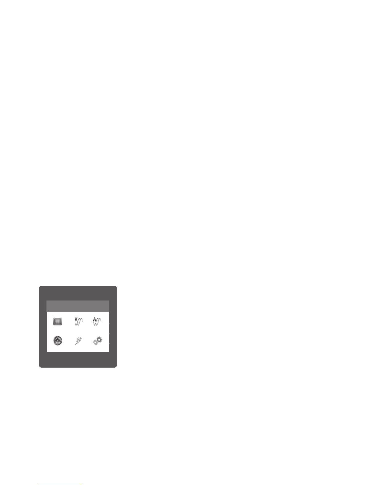
The front panel has a 3.5” Touch Screen through which the user can
move across readings, reset the energy, the available measurement
Min/Max (System Voltage and System Current) and configure the
LINE-NEUTRAL VOLTAGE
VOLTAGE
MAIN
VL2
VL2
VL2
VL2
V
VV
V
V
0.000
0.000
0.000
LINE-NEUTRAL VOLTAGE
VOLTAGE
MAIN
VL2
VL2
VL2
VL2
V
VV
V
V
0.000
0.000
0.000
LINE-NEUTRAL VOLTAGE
VOLTAGE
MAIN
VL2
VL2
VL2
VL2
V
VV
V
V
0.000
0.000
0.000
CT SECONDARY
OK
5 AMPERE
1 AMPERE
LINE-NEUTRAL VOLTAGE
VOLTAGE
MAIN
VL2
VL2
VL2
VL2
V
VV
V
V
0.000
0.000
0.000
LINE-NEUTRAL VOLTAGE
VOLTAGE
MAIN
VL2
VL2
VL2
VL2
V
VV
V
V
0.000
0.000
0.000
LINE-NEUTRAL VOLTAGE
VOLTAGE
MAIN
VL2
VL2
VL2
VL2
V
VV
V
V
0.000
0.000
0.000
MAIN MENU
POWER ENERGY SETUP
VOLTAGESYSTEM CURRENT
LINE-NEUTRAL VOLTAGE
VOLTAGE
MAIN
VL2
VL2
VL2
VL2
V
VV
V
V
0.000
0.000
0.000
LINE-NEUTRAL VOLTAGE
VOLTAGE
MAIN
VL2
VL2
VL2
VL2
V
VV
V
V
0.000
0.000
0.000
LINE-NEUTRAL VOLTAGE
VOLTAGE
MAIN
VL2
VL2
VL2
VL2
V
VV
V
V
0.000
0.000
0.000
CT SECONDARY
OK
5 AMPERE
1 AMPERE
LINE-NEUTRAL VOLTAGE
VOLTAGE
MAIN
VL2
VL2
VL2
VL2
V
VV
V
V
0.000
0.000
0.000
LINE-NEUTRAL VOLTAGE
VOLTAGE
MAIN
VL2
VL2
VL2
VL2
V
VV
V
V
0.000
0.000
0.000
LINE-NEUTRAL VOLTAGE
VOLTAGE
MAIN
VL2
VL2
VL2
VL2
V
VV
V
V
0.000
0.000
0.000
MAIN MENU
POWER ENERGY SETUP
VOLTAGESYSTEM CURRENT
product settings.
3
CT Secondary (5A or1A).

TABLE 1:
Measured Parameters
System Voltage
System Current
Frequency
Units of
Volts
Amps
Hz
Measurement
Active Import Energy (8 Digit resolution) kWh
kWh
Active Export Energy (8 Digit resolution)
System Active Power
System Reactive Power
System Apparent Power
System Power Factor
System Phase Angle
Kwatts
KVAr
KVA
Degree
kVArh
Reactive Import Energy (8 Digit resolution)
kVArh
Reactive Export Energy (8 Digit resolution)
kVAh
Apparent Energy (8 Digit resolution)
Ampere Hour (8 Digit resolution)
KAh
4
KW Import Demand
KW Export Demand
Max Current Demand
Max kVA Demand
Max KW Import Demand
Max KW Export Demand
Run Hour
On Hour
KW
Amps
KVA
KW
KW
KW
Hours
Hours
Amps
Current Demand
KVA Demand KVA

Measured Parameters Units of
Number of Interruptions
Counts
Measurement
System Voltage THD
System Current THD
%
%
Pictorial representation of Phaser Diagram
Pictorial representation of Voltage Waveform
Pictorial representation of Current Waveform
Pictorial representation of VA Waveform
5
2. Measurement Reading Screens
In normal operation the user is presented with one of the measurement reading screens out of
several screens. These screens from particular submenu may be scrolled through one at a time
in incremental order by touching the “ key” and in decremental order by touching “ key”
on screen. Viewing of that any individual parameter with large reading (eg. shown
of Line-Neutral Voltage in sub menu 2 screen 12) is also possible by touching that
particular parameter.
Screen 2 : System Max.
Screen 1 : System Parameters
(System Voltage, System
Current, System Active Power)
SUBMENU 1 : SYSTEM
KVA
Min
Angle
Max
KVAh
Ph Y
KWh
Ph B
%THD
Demand
LINE-NEUTRAL VOLTAGE
VOLTAGE
MAIN
VL2 V
0.000
0.000
LINE-NEUTRAL VOLTAGE
VOLTAGE
MAIN
VL2 V
0.000
0.000
LINE-NEUTRAL VOLTAGE
VOLTAGE
MAIN
V
0.000
0.000
SYSTEM Max. VALUES
SYSTEM
MAIN
A
V
239.9
5.005
Values (System Voltage,
Angle
Max
KWh
Ph B
Demand
LINE-NEUTRAL VOLTAGE
VOLTAGE
MAIN
VL2
VL2
VL2
VL2 0.000
0.000
0.000
LINE-NEUTRAL VOLTAGE
VOLTAGE
MAIN
VL2
VL2
VL2
VL2 0.000
0.000
0.000
LINE-NEUTRAL VOLTAGE
VOLTAGE
MAIN
VL2
VL2
VL2
VL2 0.000
0.000
0.000
SYSTEM PARAMETERS
SYSTEM
MAIN
239.6
5.001
3.592
A
V
KW
Screen 3 : System
Min. Values (System Voltage,
System Current)
System Current)
V
KW
VBR
x1000
x1000
P.F.
LINE-NEUTRAL VOLTAGE
VOLTAGE
MAIN
V
0.000
0.000
0.000
LINE-NEUTRAL VOLTAGE
VOLTAGE
MAIN
V
0.000
0.000
0.000
LINE-NEUTRAL VOLTAGE
VOLTAGE
MAIN
V
0.000
0.000
0.000
SYSTEM Min. VALUES
SYSTEM
MAIN
A
V
239.2
4.998

6
LINE-NEUTRAL VOLTAGE
VOLTAGE
MAIN
VL2 0.000
0.000
LINE-NEUTRAL VOLTAGE
VOLTAGE
MAIN
VL2 0.000
0.000
LINE-NEUTRAL VOLTAGE
VOLTAGE
MAIN
VL2 0.000
0.000
SYSTEM RUN HOUR
SYSTEM
MAIN
000001.19
hrs
Screen 4 :
VOLTAGE
MAIN
VL2 0.000
VOLTAGE
MAIN
VL2 0.000
VOLTAGE
MAIN
VL2 0.000
MAIN
Inductive
Capacitive Inductive
Capacitive
0
90
1800
2700
0
0
VL1
IL1
1
0.000
0.000
0.000
V
A
V/Div
A/Div
124.5
1.500
-P,+Q +P,+Q
-P,-Q
+P,-Q
SYSTEM
Phaser Diagram
LINE-NEUTRAL VOLTAGE
VOLTAGE
MAIN
VL2
VL2
VL2
VL2
V
VV
V
V
0.000
0.000
0.000
LINE-NEUTRAL VOLTAGE
VOLTAGE
MAIN
VL2
VL2
VL2
VL2
V
VV
V
V
0.000
0.000
0.000
LINE-NEUTRAL VOLTAGE
VOLTAGE
MAIN
VL2
VL2
VL2
VL2
V
VV
V
V
0.000
0.000
0.000
SYSTEM ON HOUR
SYSTEM
MAIN
000005.18
hrs
Screen 5 :
System Run Hour
Screen 6 :
System ON Hour
LINE-NEUTRAL VOLTAGE
VOLTAGE
MAIN
VL2
VL2
VL2
VL2
V
VV
V
V
0.000
0.000
0.000
LINE-NEUTRAL VOLTAGE
VOLTAGE
MAIN
VL2
VL2
VL2
VL2
V
VV
V
V
0.000
0.000
0.000
LINE-NEUTRAL VOLTAGE
VOLTAGE
MAIN
VL2
VL2
VL2
VL2
V
VV
V
V
0.000
0.000
0.000
SYSTEM INTERRUPTIONS
SYSTEM
MAIN
00000012
LINE-NEUTRAL VOLTAGE
VOLTAGE
MAIN
VL2
VL2
VL2
VL2
V
VV
V
V
0.000
0.000
0.000
LINE-NEUTRAL VOLTAGE
VOLTAGE
MAIN
VL2
VL2
VL2
VL2
V
VV
V
V
0.000
0.000
0.000
LINE-NEUTRAL VOLTAGE
VOLTAGE
MAIN
VL2
VL2
VL2
VL2
V
VV
V
V
0.000
0.000
0.000
SYSTEM FREQUENCY
SYSTEM
MAIN
Hz
0.000
Screen 7 : Screen 8 :
LINE-NEUTRAL VOLTAGE
VOLTAGE
MAIN
VL2
VL2
VL2
VL2
V
VV
V
V
0.000
0.000
0.000
LINE-NEUTRAL VOLTAGE
VOLTAGE
MAIN
VL2
VL2
VL2
VL2
V
VV
V
V
0.000
0.000
0.000
LINE-NEUTRAL VOLTAGE
VOLTAGE
MAIN
VL2
VL2
VL2
VL2
V
VV
V
V
0.000
0.000
0.000
SYSTEM POWER FACTOR
SYSTEM
MAIN
1.000
Screen 9 :
System Interruptions System Frequency System Power Factor
LINE-NEUTRAL VOLTAGE
VOLTAGE
MAIN
VL2
VL2
VL2
VL2
V
VV
V
V
0.000
0.000
0.000
LINE-NEUTRAL VOLTAGE
VOLTAGE
MAIN
VL2
VL2
VL2
VL2
V
VV
V
V
0.000
0.000
0.000
LINE-NEUTRAL VOLTAGE
VOLTAGE
MAIN
VL2
VL2
VL2
VL2
V
VV
V
V
0.000
0.000
0.000
SYSTEM % THD
SYSTEM
MAIN
A
V
%
%
0.000
0.000
LINE-NEUTRAL VOLTAGE
VOLTAGE
MAIN
VL2
VL2
VL2
VL2
V
VV
V
V
0.000
0.000
0.000
LINE-NEUTRAL VOLTAGE
VOLTAGE
MAIN
VL2
VL2
VL2
VL2
V
VV
V
V
0.000
0.000
0.000
LINE-NEUTRAL VOLTAGE
VOLTAGE
MAIN
VL2
VL2
VL2
VL2
V
VV
V
V
0.000
0.000
0.000
SYSTEM POWER
SYSTEM
MAIN
kVA
kVAr
kW
0.000
0.000
0.000
Screen 10 :
System % THD Screen 11 :
System Power
LINE-NEUTRAL VOLTAGE
VOLTAGE
MAIN
VL2
VL2
VL2
VL2
V
VV
V
V
0.000
0.000
0.000
LINE-NEUTRAL VOLTAGE
VOLTAGE
MAIN
V
239.6
Screen 1 : 2 Line-Neutral Voltage
SUBMENU 2 : VOLTAGE

LINE-NEUTRAL VOLTAGELINE-NEUTRAL VOLTAGE
LINE-NEUTRAL
VOLTAGE
239.6
V
BACK
(Displayed after touching any where
Line-Neutral Voltage
in the row shown in screen 12)
7
LINE-NEUTRAL VOLTAGE
VOLTAGE
MAIN
VL2
VL2
VL2
VL2
V
VV
V
V
0.000
0.000
0.000
PHASE VOLTAGE % THD
VOLTAGE
MAIN
%
0.000
Phase Voltage % THD
Screen 13 :
Screen 14 : Pictorial representation
voltagethrough submenu list)
of (Only accessedVoltage Waveform
LINE-NEUTRAL VOLTAGELINE-NEUTRAL VOLTAGELINE-NEUTRAL VOLTAGE
VOLTAGE WAVEFORM
VOLTAGE
MAIN
49.94
Hz
2.500
ms/Div
62.25
V/Div
116.5
Vrms
SUBMENU 3 : CURRENT
Screen : 15 Line Current
LINE-NEUTRAL VOLTAGE
VOLTAGE
MAIN
VL2
VL2
VL2
VL2
V
VV
V
V
0.000
0.000
0.000
LINE CURRENT
CURRENT
MAIN
A
0.000
LINE-NEUTRAL VOLTAGE
VOLTAGE
MAIN
VL2
VL2
VL2
VL2
V
VV
V
V
0.000
0.000
0.000
LINE-NEUTRAL VOLTAGE
VOLTAGE
MAIN
VL2
VL2
VL2
VL2
V
VV
V
V
0.000
0.000
0.000
LINE-NEUTRAL VOLTAGE
VOLTAGE
MAIN
VL2
VL2
VL2
VL2
V
VV
V
V
0.000
0.000
0.000
LINE CURRENT % THD
CURRENT
MAIN
%
0.000
Screen 16:
Line Current %THD
Screen 17 : Pictorial representation
( accessed Only through
of Current Waveform
current submenu list)
LINE-NEUTRAL VOLTAGELINE-NEUTRAL VOLTAGELINE-NEUTRAL VOLTAGECURRENT WAVEFORM
CURRENT
MAIN
49.94
Hz
2.500
ms/Div
30.00
A/Div
42.43
Arms
LINE-NEUTRAL VOLTAGE
VOLTAGE
MAIN
VL2
VL2
VL2
VL2
V
VV
V
V
0.000
0.000
0.000
LINE-NEUTRAL VOLTAGE
VOLTAGE
MAIN
VL2
VL2
VL2
VL2
V
VV
V
V
0.000
0.000
0.000
LINE-NEUTRAL VOLTAGE
VOLTAGE
MAIN
VL2
VL2
VL2
VL2
V
VV
V
V
0.000
0.000
0.000
PHASE REACTIVE POWER
POWER
MAIN
kVAr
0.000
Screen 18 : Phase Reactive
SUBMENU : 4 POWER
Power
Screen 20 : Phase Active
Power
LINE-NEUTRAL VOLTAGE
VOLTAGE
MAIN
VL2
VL2
VL2
VL2
V
VV
V
V
0.000
0.000
0.000
LINE-NEUTRAL VOLTAGE
VOLTAGE
MAIN
VL2
VL2
VL2
VL2
V
VV
V
V
0.000
0.000
0.000
LINE-NEUTRAL VOLTAGE
VOLTAGE
MAIN
VL2
VL2
VL2
VL2
V
VV
V
V
0.000
0.000
0.000
PHASE APPARENT POWER
POWER
MAIN
kVA
0.000
LINE-NEUTRAL VOLTAGE
VOLTAGE
MAIN
VL2
VL2
VL2
VL2
V
VV
V
V
0.000
0.000
0.000
LINE-NEUTRAL VOLTAGE
VOLTAGE
MAIN
VL2
VL2
VL2
VL2
V
VV
V
V
0.000
0.000
0.000
LINE-NEUTRAL VOLTAGE
VOLTAGE
MAIN
VL2
VL2
VL2
VL2
V
VV
V
V
0.000
0.000
0.000
PHASE ACTIVE POWER
POWER
MAIN
kW
0.000
Screen 19 : Phase Apparent
Power

LINE-NEUTRAL VOLTAGE
VOLTAGE
MAIN
VL2
VL2
VL2
VL2
V
VV
V
V
0.000
0.000
0.000
LINE-NEUTRAL VOLTAGE
VOLTAGE
MAIN
VL2
VL2
VL2
VL2
V
VV
V
V
0.000
0.000
0.000
LINE-NEUTRAL VOLTAGE
VOLTAGE
MAIN
VL2
VL2
VL2
VL2
V
VV
V
V
0.000
0.000
0.000
PHASE ANGLE
POWER
MAIN
DEG
0.000
Screen 21 : Phase Angle
LINE-NEUTRAL VOLTAGE
VOLTAGE
MAIN
VL2
VL2
VL2
VL2
V
VV
V
V
0.000
0.000
0.000
LINE-NEUTRAL VOLTAGE
VOLTAGE
MAIN
VL2
VL2
VL2
VL2
V
VV
V
V
0.000
0.000
0.000
LINE-NEUTRAL VOLTAGE
VOLTAGE
MAIN
VL2
VL2
VL2
VL2
V
VV
V
V
0.000
0.000
0.000
PHASE POWER FACTOR
POWER
MAIN
1.000
LINE-NEUTRAL VOLTAGE
VOLTAGE
MAIN
VL2
VL2
VL2
VL2
V
VV
V
V
0.000
0.000
0.000
LINE-NEUTRAL VOLTAGE
VOLTAGE
MAIN
VL2
VL2
VL2
VL2
V
VV
V
V
0.000
0.000
0.000
LINE-NEUTRAL VOLTAGE
VOLTAGE
MAIN
VL2
VL2
VL2
VL2
V
VV
V
V
0.000
0.000
0.000
CURRENT DEMAND
POWER
MAIN
A
A
0.000
0.000
LINE-NEUTRAL VOLTAGE
VOLTAGE
MAIN
VL2
VL2
VL2
VL2
V
VV
V
V
0.000
0.000
0.000
LINE-NEUTRAL VOLTAGE
VOLTAGE
MAIN
VL2
VL2
VL2
VL2
V
VV
V
V
0.000
0.000
0.000
LINE-NEUTRAL VOLTAGE
VOLTAGE
MAIN
VL2
VL2
VL2
VL2
V
VV
V
V
0.000
0.000
0.000
VA DEMAND
POWER
MAIN
kVA
kVA
0.000
0.000
Screen 22 : Phase Power
Screen 23 :
Current Demand
Screen 24 :
VA Demand
LINE-NEUTRAL VOLTAGE
VOLTAGE
MAIN
VL2
VL2
VL2
VL2
V
VV
V
V
0.000
0.000
0.000
LINE-NEUTRAL VOLTAGE
VOLTAGE
MAIN
VL2
VL2
VL2
VL2
V
VV
V
V
0.000
0.000
0.000
LINE-NEUTRAL VOLTAGE
VOLTAGE
MAIN
VL2
VL2
VL2
VL2
V
VV
V
V
0.000
0.000
0.000
IMPORT ACTIVE DEMAND
POWER
MAIN
kW
kW
0.000
0.000
LINE-NEUTRAL VOLTAGELINE-NEUTRAL VOLTAGELINE-NEUTRAL VOLTAGEPHASE WAVEFORM
POWER
MAIN
116.5
V
49.94
Hz
2.500
ms/Div
62.25
V/Div
42.43
A
210.4
DEG
LINE-NEUTRAL VOLTAGE
VOLTAGE
MAIN
LINE-NEUTRAL VOLTAGE
VOLTAGE
MAIN VOLTAGE
MAIN
EXPORT ACTIVE DEMAND
POWER
MAIN
kW
kW
0.000
0.000
Screen 25 :
Import Active Demand
Screen :26
Export Active Demand
Screen 27 : Pictorial representation
(only accessed through power submenu list)
Of Phase Waveform
8
Demand
Max
Demand
Max
Demand
Max
Demand
Max
Demand
Demand Demand
Demand
Factor
LINE-NEUTRAL VOLTAGE
VOLTAGE
MAIN
VL2
VL2
VL2
VL2
V
VV
V
V
0.000
0.000
0.000
LINE-NEUTRAL VOLTAGE
VOLTAGE
MAIN
VL2
VL2
VL2
VL2
V
VV
V
V
0.000
0.000
0.000
LINE-NEUTRAL VOLTAGE
VOLTAGE
MAIN
VL2
VL2
VL2
VL2
V
VV
V
V
0.000
0.000
0.000
ACTIVE ENERGY IMPORT
ENERGY
MAIN
0.0000000
kWh
SUBMENU : 5 ENERGY
Screen 28 :
Active Energy Import
Screen 29 :
LINE-NEUTRAL VOLTAGE
VOLTAGE
MAIN
VL2
VL2
VL2
VL2
V
VV
V
V
0.000
0.000
0.000
LINE-NEUTRAL VOLTAGE
VOLTAGE
MAIN
VL2
VL2
VL2
VL2
V
VV
V
V
0.000
0.000
0.000
LINE-NEUTRAL VOLTAGE
VOLTAGE
MAIN
VL2
VL2
VL2
VL2
V
VV
V
V
0.000
0.000
0.000
ACTIVE ENERGY EXPORT
ENERGY
MAIN
0.0000000
kWh
Active Energy Export

LINE-NEUTRAL VOLTAGE
VOLTAGE
MAIN
VL2
VL2
VL2
VL2
V
VV
V
V
0.000
0.000
0.000
LINE-NEUTRAL VOLTAGE
VOLTAGE
MAIN
VL2
VL2
VL2
VL2
V
VV
V
V
0.000
0.000
0.000
LINE-NEUTRAL VOLTAGE
VOLTAGE
MAIN
VL2
VL2
VL2
VL2
V
VV
V
V
0.000
0.000
0.000
REACTIVE ENERGY EXPORT
ENERGY
MAIN
0.0000000
kVArh
Screen 35 :
LINE-NEUTRAL VOLTAGE
VOLTAGE
MAIN
VL2
VL2
VL2
VL2
V
VV
V
V
0.000
0.000
0.000
LINE-NEUTRAL VOLTAGE
VOLTAGE
MAIN
VL2
VL2
VL2
VL2
V
VV
V
V
0.000
0.000
0.000
LINE-NEUTRAL VOLTAGE
VOLTAGE
MAIN
VL2
VL2
VL2
VL2
V
VV
V
V
0.000
0.000
0.000
REACTIVE ENERGY IMPORT
ENERGY
MAIN
0.0000000
kVArh
Reactive Energy Import
Reactive Energy Export
Screen 36 :
LINE-NEUTRAL VOLTAGE
VOLTAGE
MAIN
VL2
0.000
0.000
0.000
LINE-NEUTRAL VOLTAGE
VOLTAGE
MAIN
VL2
0.000
0.000
0.000
LINE-NEUTRAL VOLTAGE
VOLTAGE
MAIN
VL2
0.000
0.000
0.000
APPARENT ENERGY
ENERGY
MAIN
0.0000000
kVAh
LINE-NEUTRAL VOLTAGE
VOLTAGE
MAIN
VL2
VL2
VL2
VL2
V
VV
V
V
0.000
0.000
0.000
LINE-NEUTRAL VOLTAGE
VOLTAGE
MAIN
VL2
VL2
VL2
VL2
V
VV
V
V
0.000
0.000
0.000
LINE-NEUTRAL VOLTAGE
VOLTAGE
MAIN
VL2
VL2
VL2
VL2
V
VV
V
V
0.000
0.000
0.000
AMPERE HOUR
ENERGY
MAIN
0.0000000
kAh
Screen :37
Screen 38 :
Apparent Energy
Ampere Hour
9

10
AMPERE
HOUR
APPARENT
ENERGY
REACTIVE ENERGY
EXPORT
REACTIVE ENERGY
IMPORT
ACTIVE ENERGY
EXPORT
ACTIVE ENERGY
IMPORT
RESET
PARAMETERS
COMMUNICATION
MAIN MENU
SYSTEM
SYSTEM TYPE
PT PRIMARY
PT SECONDARY
CT PRIMARY
CT SECONDARY
DEMAND
NOISE CUTOFF
AUTO SCROLL
(Sec 3.2.1.1)
(Sec 3.2.1.2)
(Sec 3.2.1.3)
(Sec 3.2.1.4)
(Sec 3.2.1.5)
(Sec 3.2.1.7)
Parameter Screens
INTEGRATION
TIME
LOW CURR.
CURRENT
VOLTAGE
SYSTEM
Max. VOLTAGE
PHASER
RUN HOUR
A
A
FREQUENCY
SYSTEM
PARAMETERS
And CURRENT
Min. VOLTAGE
And CURRENT
ON HOUR
No. OF
INTERRUPTIONS
CT SECONDARY
DEMAND
NOISE CUTOFF
AUTO SCROLL
(Sec 3.2.1.5)
(Sec 3.2.1.7)
INTEGRATION
TIME
LOW CURR.
POWER FACTOR
SYSTEM
POWER
THD.VOLTAGE
AND CURRENT
(Sec 3.2.2.3)
PHASE VOLTAGE
% THD
Line Current
OPTIONS
(Sec 3.2.4)
POWER
CHANGE
PASSWORD
(Sec 3.1)
ENERGY
AA
A
B
A
B
LINE CURRENT
% THD
DIAGRAM
Line to Neutral
VOLTAGE
(Sec 3.2.2.3)
WAVEFORM
WAVEFORM
CURRENT
PHASE
WAVEFORM
EXPORT
ACTIVE DEMAND
IMPORT
ACTIVE DEMAND
APPARENT
DEMAND
CURRENT
DEMAND
PHASE
POWER FACTOR
PHASE ACTIVE
POWER
PHASE APPARENT
POWER
PHASE REACTIVE
POWER
PHASE
ANGLE

11
(Acc. To Table 2)
(Sec 3.2.4.1.2.1)
PARAMETER
SELECTION
CONFIGURATION
SELECTION
(Sec 3.2.4.1.2.2)
TRIP POINT
10% to 100%/120%
(Sec 3.2.4.1.2.3)
HYSTERESIS
0.5% to 50%
(Sec 3.2.4.1.2.4)
ENERGIZING
DELAY
1s to 10s
(Sec 3.2.4.1.2.5)
1 s to 10s
(Sec 3.2.4.1.2.6)
DE-ENERGIZING
DELAY
PULSE
OUTPUT
(Sec 3.2.4.1.1)
LIMIT
OUTPUT
(Sec 3.2.4.1.2)
PARAMETER
SELECTION
(Sec 3.2.4.1.1.1)
PULSE RATE
(Pulse Divisor Rate)
1, 10, 100, 1000
PULSE RATE
R
(Sec 3.2.4.1.1.3)
PULSE
DURATION
60,100,200
(Sec 3.2.4.1.1.2)
Rs485 ADDRESS
(Sec 3.2.2.1)
ANALOG OUTPUT 1
(Sec 3.2.4.3)
ANALOG OUTPUT 2
selection)
(Acc. To Table 2)
(Sec 3.2.4.4)
ANALOG OUTPUT 2
(Analog 2 parameter
RS485 PARITY
(Sec 3.2.2.3)
PT PRIMARY
(Sec 3.2.1.1)
PT SECONDARY
(Sec 3.2.1.2)
CT PRIMARY
(Sec 3.2.1.3)
CT SECONDARY
(Sec 3.2.1.4)
AUTO SCROLL
(Sec 3.2.1.6)
NOISE CUTOFF
(Sec 3.2.1.7)
LOW CURR.
RS485
(Sec 3.2.2.2)
BAUD RATE
RS485
(Sec 3.2.2.2)
BAUD RATE
ANALOG OUTPUT 1
(Analog 1 parameter
selection)
(Acc. To Table 2)
(Sec 3.2.4.2)
RELAY
OUTPUT 2
DEMAND
(Sec 3.2.1.5)
INTEGRATION
TIME
RESET MAX VOLTAGE & CURRENT
RESET MIN VOLTAGE & CURRENT
RESET RUN-HOUR,ON-HOUR
RESET AUX INTERRUPT COUNT
Select any option by
RESET ALL
PASSWORD
SYSTEM
(Sec 3.2.1)
Setup Parameter Screens
PARAMETERS
ENTER
SYSTEM
(Sec 3.2.1)
PARAMETERS
PARAMETERS
COMMUNICATION
(Sec 3.2.2)
PARAMETERS
(Sec 3.1)
BRIGHTNESS
& CONTRAST
(Sec 3.2.5)
CHANGE
PASSWORD
(Sec 3.1.1)
RESET
(Sec 3.2.3)
PARAMETERS
OPTIONS
OUTPUT
(Sec 3.2.4)
touching on it.
(Sec 3.2.4.1)
RELAY
OUTPUT 1
RESET DEMAND PARAMETERS
RESET ALL ENERGIES
RS485
(Sec 3.2.1.8)
ENERGY ON
RESET COUNT
(Sec 3.2.1.9)
ENERGY DIGIT

3.1. Password Protection
Password protection can be enabled to prevent unauthorised access to set-up screens, by default
password is “0000”.
Password protection is enabled by selecting any four digit number.
3. Programming
The following sections comprise step by step procedures for configuring the instrument for
individual user requirements.
To access the set-up screens touch on the “ SETUP ” icon in Main Menu. This will take the
User into the Password Protection Entry Stage(Section 3.1).
After touching “ SETUP” icon Password protection screen is
displayed. Screen consists of 0 to 9 digit input keypad for entering
the password very similar to any calculator in touchscreen mobile.
“Enter Password is displayed on screen at start ” so that user can enter
password using displayed keypad.
Touching “ key” will display 1 in display area, similarly user can
1
enter remaining 3 digits.
DEL
For deleting any digit while entering password, user can touch
SETUP
ENTER PASSWORD
1 2 3
456
78 9
0BACK
DEL
ENTER
SETUP
1
“ key”.
12
1 2 3
456
78 9
0BACK
DEL
ENTER

After entering the complete password user needs to confirm password
by touching “ key”.
ENTER
SETUP
1234
If Entered password is correct then “Password Accepted” is displayed
on screen & user will enter into setup menu.
Password confirmed.
SETUP
PASSWORD ACCEPTED
If Entered password is wrong then Password “ Rejected” is displayed
on screen & user need to re-enter the password
Password Incorrect.
SETUP
PASSWORD REJECTED.
After wrong password is entered, user needs to touch “ key” for
trying another password.
ENTER
PASSWORD
PRESS ENTER TO TRY AGAIN
13
1 2 3
456
78 9
0BACK
DEL
ENTER
1 2 3
456
78 9
0BACK
DEL
ENTER
1 2 3
456
78 9
0BACK
DEL
ENTER
1 2 3
456
78 9
0BACK
DEL
ENTER

Change Password Option is the second last option in list of “SETUP”
submenu, touch anywhere in “ Change so can be accessed by a simple
Password” row.
In this screen user first needs to enter the current password.
3.1.1 Change Password
PASSWORD
ENTER CURRENT PASSWORD
& now user can enter the new 4 digit password.
After input of correct password,“PASSWORD ACCEPTED”is displayed
PASSWORD
ENTER NEW PASSWORD
PASSWORD
PASSWORD CHANGED
After entering new password user needs to touch “ key” to
After confirming “PASSWORD displayed on screen,CHANGED” is
which ensures successful changing of the password.
ENTER
New Password confirmed.
confirm.
3.2 Menu selection.
After entering in the SUBMENU 6 - SETUP, user will be asked to enter password & after input of
correct password list of following parameters will be displayed on screen :-
3.2.1 SYSTEM PARAMETERS
3.2.2 COMMUNICATION PARAMETERS
14
1 2 3
456
78 9
0BACK
DEL
ENTER
1 2 3
456
78 9
0BACK
DEL
ENTER
1 2 3
456
78 9
0BACK
DEL
ENTER

Touching on SYSTEM PARAMETER will open the system parameters list screen.Then these
touching the “ key” and in decremental order by touching “ key” on given touch screen.
screens from particular parameter may be scrolled through one at a time in incremental order by
3.2.1 System Parameters Selection
After entering in the “SYSTEM PARAMETERS”, List of following parameters will be displayed :-
3.2.1.1 PT PRIMARY(L-L)
3.2.1.2 PT SECONDARY(L-L)
3.2.1.3 CT PRIMARY
3.2.1.4 CT SECONDARY
3.2.1.5 DEMAND INTEGRATION TIME
3.2.1.6 AUTO SCROLL
3.2.1.7 LOW CURRENT NOISE CUTOFF
3.2.3 RESET PARAMETERS
3.2.4 OUTPUT OPTIONS
3.2.5 BRIGHTNESS & CONTRAST
15
Here again 0 to 9 digit input keypad is provided to set value of PT
Primary, & user can confirm this value with a simple touch “
3.2.1. Primary Value1 Potential Transformer
The nominal full scale voltage will be displayed as Line to Line Voltage.
LINE-NEUTRAL VOLTAGELINE-NEUTRAL VOLTAGELINE-NEUTRAL VOLTAGEPT PRIMARY
ENTER PT PRIMARY VALUE(L-L)
This screen can be accessed only from system parameters list menu.
key”. “ key” is used to multiply value by 1000.
ENTER
In case presently displayed Potential Transformer Primary value together
with the Current Transformer Primary value, previously set, would result
in a maximum power of greater than 666.6 MVA per phase,”Invalid
value” will be displayed. Then the valid range will be displayed.
K
1 2 3
456
78 9
DEL
ENTER
0KBACK
.
3.2.1.8 ENERGY ON RS485
3.2.1.9 ENERGY DIGIT RESET COUNT

LINE-NEUTRAL VOLTAGELINE-NEUTRAL VOLTAGELINE-NEUTRAL VOLTAGEPT PRIMARY
INVALID VALUE
Valid range of PT primary setting value is from
If value outside the range is entered, It will display “INVALID VALUE”
followed by correct range of parameter.
100 VL-L to 692.8 KVL-L.
3.2.1.2 Potential Transformer secondary Value
The value must be set to the nominal full scale secondary voltage which will be obtained from the
the Transformer when the potential transformer(PT)primary is supplied with the voltage defined
in 3.2.1.1 potential transformer primary voltage. The ratio of full scale primary to full scale
secondary is defined as the transformer ratio.
Here again 0 to 9 digit input keypad is provided to set value of PT
Secondary, & user can confirm this value with a simple touch on
This screen can be accessed only from system parameters list menu.
“ key”.
ENTER
LINE-NEUTRAL VOLTAGELINE-NEUTRAL VOLTAGELINE-NEUTRAL VOLTAGEPT SECONDARY
ENTER PT SECONDARY VALUE(L-N)
16
1 2 3
456
78 9
DEL
ENTER
0KBACK
.
1 2 3
456
78 9
DEL
ENTER
0KBACK
.
Potential Transformer secondary ranges for various Input Voltages
63.5V L-N 57.73V - 69.28V L-N
69.86V - 138.56V L-N
139.14V - 277.12V L-N
133.0V L-N
239.6V L-N
Valid range of PT value is from secondary setting 241.0 to 480.0.
If value outside the range is entered, It will display “INVALID VALUE”
followed by correct range of parameter.
LINE-NEUTRAL VOLTAGELINE-NEUTRAL VOLTAGELINE-NEUTRAL VOLTAGEPT SECONDARY
INVALID VALUE for 415 VL-L. Please refer the table bellow for different ranges.
1 2 3
456
78 9
DEL
ENTER
0KBACK
.

3.2.1.3 Current Transformer Primary Value
The nominal Full Scale Current that will be displayed as the Line currents. This screen
enables the user to display the Line currents inclusive of any transformer ratios, the values
displayed represent the Current in Amps.
In case presently displayed Current Transformer Primary Value
together with the Potential Transformer Primary Value results in a
maximum power of greater than 666.6 MVA, “invalid value” will be displayed. Example:
If primary value of PT is set as 692.8kV L-L (max value) then primary value of Current is
The “Maximum Power” restriction of 666.6 MVA refers to 120% of nominal current and
LINE-NEUTRAL VOLTAGELINE-NEUTRAL VOLTAGELINE-NEUTRAL VOLTAGECT PRIMARY
ENTER CT PRIMARY VALUE
Here again 0 to 9 digit input keypad is provided to set value of CT
Primary & user can confirm this value with a simple touch on “
This screen can be accessed only from system parameters list menu.
key”. “ key” is used to multiply value by 1000.
ENTER
K
120% of nominal voltage, i.e, 462.96 MVA nominal power per phase.
restricted to 1157A.
17
1 2 3
456
78 9
DEL
ENTER
0KBACK
.
Valid range of T primary setting value is from C 1 to 9999. If value
outside VALUE” the range is entered, It will display “INVALID
followed by correct range of parameter.
LINE-NEUTRAL VOLTAGELINE-NEUTRAL VOLTAGELINE-NEUTRAL VOLTAGECT PRIMARY
INVALID VALUE
1 2 3
456
78 9
DEL
ENTER
0KBACK
.

3.2.1.4 Current Transformer Secondary Value
This screen is used to set the secondary value for Current Transformer.
Touching particular option will select that option. radio button in front of
Two & options: 1 AMPERE 5 AMPERE are displayed on screen.
LINE-NEUTRAL VOLTAGE
VL2
VL2VL2
V
VVV
0.000
0.000
LINE-NEUTRAL VOLTAGE
VL2
VL2VL2
V
VVV
0.000
0.000
LINE-NEUTRAL VOLTAGE
VL2
VL2VL2
V
VVV
0.000
0.000
CT SECONDARY
5 AMPERE
1 AMPERE
LINE-NEUTRAL VOLTAGE
VL2
VL2VL2
V
VVV
0.000
0.000
LINE-NEUTRAL VOLTAGE
VL2
VL2VL2
V
VVV
0.000
0.000
LINE-NEUTRAL VOLTAGE
VL2
VL2VL2
V
VVV
0.000
0.000
CT SECONDARY
1 AMPERE
5 AMPERE
MAINMAINMAINMAINMAINMAIN
OK BACK
Touch on “ key” will confirm the setting. Touching the
OK
“ key” will keep the old selected setting and will return
BACK
to previous menu.
3.2.1.5 Demand Integration Time
This screen is used to set the period over which current and power
readings are to be integrated.
radio button in front of particular option will select that option.
Four options: 8, 15, 20, 30 Minutes are displayed on screen. Touching
Touch on “ key” will confirm the setting.
OK
LINE-NEUTRAL VOLTAGE
VL2
VL2VL2 0.000
0.000
LINE-NEUTRAL VOLTAGE
VL2
VL2VL2 0.000
0.000
LINE-NEUTRAL VOLTAGE
VL2
VL2VL2 0.000
0.000
CT SECONDARY
5 AMPERE
1 AMPERE
LINE-NEUTRAL VOLTAGE
VL2
VL2VL2 0.000
0.000
LINE-NEUTRAL VOLTAGE
VL2
VL2VL2 0.000
0.000
LINE-NEUTRAL VOLTAGE
VL2
VL2VL2 0.000
0.000
DEMAND INTEGRATION TIME
8 MINUTES
15 MINUTES
20 MINUTES
30 MINUTES
MAINMAINMAINMAINMAINMAIN
OK BACK
return to previous menu.
Touching the “ key” will keep the old selected setting and will
BACK
18
3.2.1.6 Auto Scrolling
This screen allows user to enable screen scrolling. Seven options :
POWER, ENERGY & NONE on screen. Touching radio are displayed
ALL, SYSTEM, VOLTAGE, CURRENT
button in front of particular option will select that option. Selecting
Touch on “ key” will confirm the setting.
OK
particular option means, only screens which are under that submenu
will be scrolled automatically. Selecting NONE will disable Auto-Scroll.
LINE-NEUTRAL VOLTAGE
VL2
VL2
VL2 VV
V
V
0.000
0.000
LINE-NEUTRAL VOLTAGE
VL2
VL2
VL2 VV
V
V
0.000
0.000
LINE-NEUTRAL VOLTAGE
VL2
VL2
VL2 VV
V
V
0.000
0.000
CT SECONDARY
1 AMPERE
LINE-NEUTRAL VOLTAGE
VL2
VL2
VL2 VV
V
V
0.000
0.000
LINE-NEUTRAL VOLTAGE
VL2
VL2
VL2 VV
V
V
0.000
0.000
LINE-NEUTRAL VOLTAGE
VL2
VL2
VL2 VV
V
V
0.000
0.000
AUTO - SCROLL
ALL
VOLTAGE
POWER
NONE
SYSTEM
CURRENT
ENERGY
MAINMAINMAINMAINMAINMAIN
OK BACK
Touching the “ key” will keep the old selected setting and will return to previous menu.
BACK
Table of contents
Other Ziegler Measuring Instrument manuals