ZIGOR ZGR TOWER PRO 6 User manual

Operation Manual
ZGR TOWER PRO 6 10 KVA
Online single-phase UPS
www.zigor.com


ZGR TOWER PRO 6 10 KVA
Operation manual
www.zigor.com
3
INDEX
1PRECAUTIONS.....................................................................................................................................................5
1.1 General precautions.....................................................................................................................................5
1.2 Storage precautions.....................................................................................................................................6
1.3 Environmental precautions ..........................................................................................................................7
1.4 Precautions on the transportation of the unit..............................................................................................7
1.5 Precautions on receiving the unit................................................................................................................. 8
1.6 Symbol Description...................................................................................................................................... 8
2GENERAL DESCRIPTION.....................................................................................................................................9
2.1 Introduction..................................................................................................................................................9
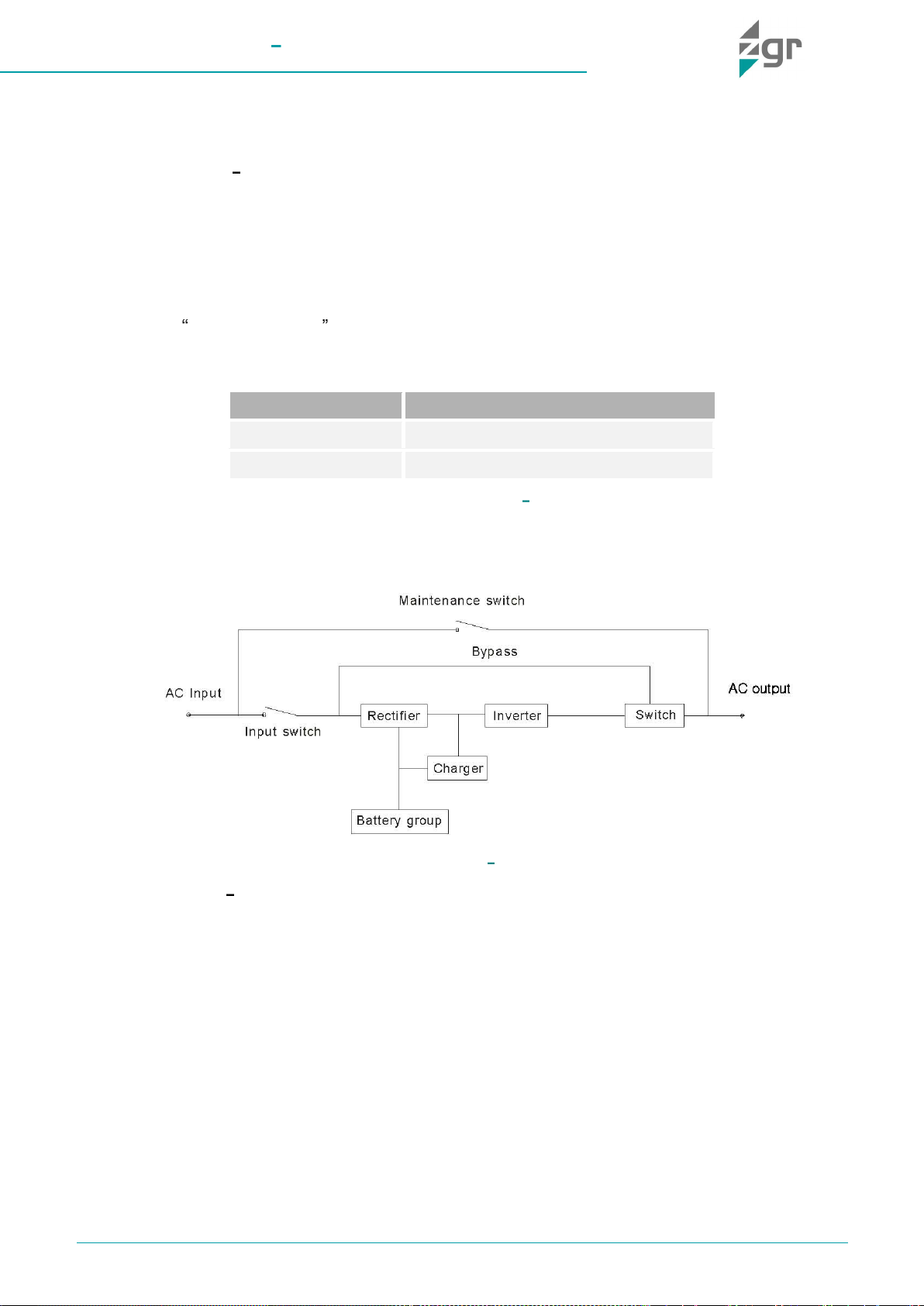
2.2 Operation principle.......................................................................................................................................9
2.3 Main characteristics...................................................................................................................................10
2.4 Construction of ZGR TOWER PRO 6 10 KVA.........................................................................................10
3INSTALLATION...................................................................................................................................................11
3.1 Reception of material.................................................................................................................................11
3.2 Installation conditions ................................................................................................................................11
3.3 Mechanical installation...............................................................................................................................12
3.4 Electrical installation ..................................................................................................................................12
External Protective Devices ...................................................................................................................12
UPS input and output connection..........................................................................................................14
External battery connection (for extend model only - LBT)...................................................................14
3.5 ..............................................................................................................................15
4OPERATION OF ZGR TOWER PRO 6 10 KVA................................................................................................16
4.1 Start up and turn off UPS...........................................................................................................................16
Normal mode..........................................................................................................................................16
Battery mode (Stored Energy Mode) .....................................................................................................17
Bypass mode .........................................................................................................................................17
ECO Mode..............................................................................................................................................17
Parallel redundancy mode (system expansion) .....................................................................................17
Parallel function setup............................................................................................................................17
Parallel cable installation........................................................................................................................18
Bypass mode in parallel working mode.................................................................................................19
4.2 Initial start-up .............................................................................................................................................19
Connection with Utility...........................................................................................................................19
Black (Cold) start procedure..................................................................................................................20
Inverter Off .............................................................................................................................................20
Disconnecting with Utility.......................................................................................................................21
4.3 LCD control panel ......................................................................................................................................21
Display information ................................................................................................................................21
Available interfaces in the LCD display..................................................................................................23
4.4 Parameters setting.....................................................................................................................................24
Operation Mode setting (mod)...............................................................................................................24
Operation Output voltage setting (OPV) ................................................................................................25
Operation Output frequency setting (OPF) ............................................................................................25

ZGR TOWER PRO 6 10 KVA
Operation manual
www.zigor.com
4
Battery capacity setting (bAH) ...............................................................................................................25
Battery number/quantity setting (bN).....................................................................................................26
Bypass High Level switch setting (HLS) ................................................................................................26
Bypass Low Level switch setting (LLS)..................................................................................................27
Buzzer Mute Setting (bZ) .......................................................................................................................27
Battery Test Setting (tSt)........................................................................................................................27
Parallel ID setting (PId).......................................................................................................................28
Parallel quantity setting (PN)..............................................................................................................29
Parallel redundancy quantity setting (PrN).........................................................................................29
4.5 List of possible alarms ...............................................................................................................................30
5COMMUNICATIONS...........................................................................................................................................32
5.1 Communications........................................................................................................................................32
Connection of the UPS communication cables.....................................................................................32
6TROUBLESHOOTING.........................................................................................................................................33
6.1 Malfunctions of ZGR TOWER PRO 6 10 KVA.........................................................................................33
7MAINTENANCE ..................................................................................................................................................34
7.1 Battery maintenance..................................................................................................................................34
8TECHNICAL SPECIFICATIONS..........................................................................................................................36
9STANDARDS.......................................................................................................................................................38
10 WARRANTY....................................................................................................................................................39
© 2022, ZIGOR
All rights reserved. The total or partial reproduction of this User Manual, or its transmission of any type or by any means, be
this mechanical or electronic, by means of photocopies, registration or other information storage or recovery procedure,
without the permission of the editor, is totally forbidden.
The contents of this manual are exact at the time it was printed. However, with the intention of complying with our aim of
continuous development and improvement, the manufacturer reserves the right to change the specifications of the product,
its operation or the contents of the Operating Manual without prior warning.

ZGR TOWER PRO 6 10 KVA
Operation manual
www.zigor.com
5
1PRECAUTIONS
1.1 General precautions
For your own safety and that of the unit, you must read and understand the instructions contained in this
document before starting work.
Keep these instructions in a place accessible to all the personnel who work with the unit so that they can be
consulted.
Only expert and duly authorised personnel may operate our units.
Danger warnings. When handling or accessing the interior of the ZGR TOWER PRO 6 10 KVA,
please remember that some parts may be live. Pay special attention to soldering points, printed
circuits, connecting terminals, relay contacts, etc. Before opening the equipment, disconnect the
voltage of all poles (both alternating and direct) and wait at least 5 minutes for the internal condensers
to discharge.
Arbitrary modifications are forbidden. The unit must not be subjected to any modification regarding its
any damage caused as a result of the modification. In particular, all repair work, soldering of printed circuit boards
and replacing of components, modules and printed circuit boards, without the express authorisation of ZIGOR, is
forbidden. Should spare parts be used, only ZIGOR original parts shall be utilised.
Use the unit for the purpose for which it was designed. The system supplied must be used only for the
purpose for which it was designed. Any other use is strictly forbidden. ZIGOR cannot accept responsibility for any
damage that might result from its use for any other purpose. In such cases, the user shall assume exclusive
responsibility for any risk. The use for which the unit was designed is defined in the documentation. The system
shall be exposed only to admissible environmental conditions. These are defined in the technical details provided
for the equipment.
ZIGOR accepts no responsibility for any inadequate, negligent or incorrect installation of the equipment.
Please follow the indications set out below to operate under conditions of complete safety:
•The System must be checked once the installation has been completed by a qualified technician and
before being put into operation. Should these indications not be adhered to, the warranty shall be
considered null and void.
•These units do not contain parts usable for other purposes by the user.
•Do not power up the device before a technician has checked it.
•Given the risk of electric shock or burns, do not try to open the device.
•Work inside the cabinet should be undertaken only by qualified personnel who are familiar with the safety
measures to be applied and the specific technical characteristics of the unit.
•The unit does not contain any user repairable or replaceable elements. In the case of any malfunction or
problems operating the unit, please contact ZIGOR.
•Do not place the system near power magnets as this might cause a malfunction.
•Do not block or cover the ventilation grills in the housing.
•The ZGR TOWER PRO 6 10 KVA is designed in accordance with current Spanish legislation. Check
these regulations against those corresponding to the country in which the unit is to be installed and
against the most restrictive regulations of the electricity supplier.
•All user controls are accessible from the exterior.
•This system has been designed for industrial use and not for domestic-commercial use.
WARNING
This supply equipment contains a lethal voltage Comply with the instructions set out in this manual to avoid any
risk of electrical shock.

ZGR TOWER PRO 6 10 KVA
Operation manual
www.zigor.com
6
•Even though all the safety systems are in place, before touching any working parts, you must check that
they are not live.
•This system has been designed for industrial use and not for domestic-commercial use.
•If any liquid is spilt accidentally on the System, disconnect this and consult ZIGOR personnel.
•During assembly work, start-up or maintenance, wear goggles to avoid any damage to your eyes due to
accidental electric arcing.
•Use only insulated tools.
•The unit must be protected against rain and excess humidity and installed in a clean atmosphere, without
inflammable liquids, gases or oxidising substances.
•The battery may pose a risk of electric shock or burns due to its high short circuit current.
•If the batteries lose electrolyte or are physically damaged, they must be placed in a container in resistant
to corrosive liquids (acids or alkaline according to the type of battery) and prepared in accordance with
local regulations.
•If the electrolyte comes into contact with the skin, the affected area must be washed immediately with
clean water.
•Only authorized personnel should repair or install the batteries.
•Should you have any problems with the contents of this manual, you must ask ZIGOR for assistance.
1.2 Storage precautions
The store where the material is kept must protect the material from the elements, risk of flooding or contact with
water.
The material shall be protected from any risk of overheating due to exposure to direct sunlight or through
windows.
The recommended storage temperature is from 15ºC to 25ºC. An increase of 10ºC can reduce the service life of
the battery by 50%. The recommended relative humidity is from 30% to 90%.
To avoid any risk of mechanical shock, do not stack the packages. These must be placed in accordance with the
silkscreen printed details on the boxes used for packaging.
Before storing, charge the UPS 5 hours. Store the UPS covered and upright in a cool, dry location. During
storage, recharge the battery in accordance with the Table 1-1:
STORAGE TEMPERATURE
RECHARGE FREQUENCY
CHARGING DURATION
-25°C - 40°C
Every 3 months
1-2 hours
40°C - 45°C
Every 2 months
1-2 hours
Table 1-1 Storage temperatures
WARNING
Any failure to respect these precautions may render the product warranty null and void.

ZGR TOWER PRO 6 10 KVA
Operation manual
www.zigor.com
7
1.3 Environmental precautions
1.4 Precautions on the transportation of the unit
Please transport the UPS system only in the original package to protect against shock and impact. The procedure
to transport of the UPS to the final location should follow the procedure:
1. Use a pallet truck to transport the UPS to the installation position.
2. Check the UPS packing.
3.
4. Check the appearance to see if the UPS is damaged or not during the transportation, do not switch on the
UPS if any damage found. Please contact the dealer right away.
5. Check the accessories according to the packing list and contact the dealer in case of missing parts.
Dispose of the packaging in an ecological way: ZIGOR, based on the exceptions detailed
in the First Additional Provision of Law 11/1997 on commercial or industrial packaging,
informs that the final holder of the waste of used containers and packaging, as responsible
for them, you must deliver them in appropriate conditions for reuse, to an authorized
recuperator, recycler or re-valuer.
The subsets of the system are recyclable products and cannot be treated as household / municipal waste at
the end of its useful life.
To preserve the environment, manage them in accordance with current environmental regulations and
requirements in each country or community. In case of doubt, consult the manufacturer.
Correct product disposal: This electrical-electronic device (AEE) is marked with the
symbol of compliance with the European Directive 2012/19 / EU (WEEE) regarding used
electrical and electronic equipment (Waste electrical and electronic equipment WEEE, RD
110/2015).
The Directive provides the general framework valid throughout the European Union for the
removal and reuse of waste from EEE.
To dispose of this product and ensure its proper management, follow the current local
environmental legislation and regulations. In this way it will contribute to conserve the
environment.
Correct disposal of batteries: Used batteries are reusable consumer products and a recycling
process must be carried out.
Used batteries that do not go through the recycling process must be disposed of according to
the instructions regarding special waste, in accordance with the regulations and environmental
requirements in force in each country or community. This requirement applies in the European
Union and in those places where separate collection systems are available.
In case of doubt, consult the manufacturer.
In this way it will contribute to conserve the environment.

ZGR TOWER PRO 6 10 KVA
Operation manual
www.zigor.com
8
1.5 Precautions on receiving the unit
Visually check that the UPS location is adequate by checking its characteristics (clean, free of leaks with good
ventilation); the floor must be level and have sufficient load resistance for the equipment.
Checking the material
•On receiving the material, a visual inspection should be made in order to detect any anomalies that may
have occurred during transport.
•List and check all the items indicated on the delivery note. Should any component be missing, notify the
forwarding agent within the established deadline.
•Extract all parts from the packaging and examine the unit for any damage caused during transport.
•Report any damage to the forwarding agent and ZlGOR.
•Check that the material delivered corresponds to the delivery note. Check the manufacturer's label placed
at the rear or on one side of the unit.
•Responsibility for the loss or damage of Products shall transfer to the Customer from the moment ZIGOR,
places these at his disposal in the place indicated by the Customer.
1.6 Symbol Description
The safety symbols cited in this manual are shown in Table 1-2, which are used to inform readers of safety issues
that should be obeyed when installation, operation and maintenance.
SAFETY SYMBOL
INDICATION
Attention
Static discharge sensitive
Risk of electric shock
Table 1-2 Security symbol meanings
SYMBOL
INDICATION
Turn ON/OFF the UPS
Alternating current source (AC)
Direct current source (DC)
Protective ground
Table 1-3 Symbol meaning
From then on, the customer will have 24 hours to make any claim under guarantee for any anomaly in the
amount or quality of the products received, providing details of the material received in bad condition after
reporting this circumstance on the forwarding agent's delivery note on reception.
Should the customer not report any defect within 24 hours, it will be understood that he has accepted delivery
of the unit.

ZGR TOWER PRO 6 10 KVA
Operation manual
www.zigor.com
9
2GENERAL DESCRIPTION
2.1 Introduction
ZGR TOWER PRO 6 10 KVA is an intelligent, Single phase in - Single phase out, high frequency online UPS
double conversion online technology to protect your installation with maximum efficiency. Thanks to its excellent
electrical performance, perfect intelligent monitoring, its grid functions and an intelligent appearance, and
compliance with regulations on safety and electromagnetic compatibility, the UPS responds to an international
advanced level.
In this range of equipments there are 6 and 10 kVA available models with parallel function included up to 4 units.
This feature allows a gradual upgrade of user installation without the need to invest in a new UPS. It also
integrates Frecuency Converter function that enables to adapt the operating frequency in different countries 50 /
60Hz. Ideal for business continuity applications that require long battery operation.
It is possible to extend autonomy several hours using external batteries (LBT versions) with reinforced battery
charger.
POWER
NUMBER OF BATTERIES
6 kVA
16 ~20 external batteries (12 V/ud)
10 kVA
16 ~20 external batteries (12 V/ud)
Table 2-1 ZGR TOWER PRO 6 10 KVA range
2.2 Operation principle
Fig. 2-1 ZGR TOWER PRO 6 10 KVA block diagram
ZGR TOWER PRO 6 10 KVA combines the following components:
•Input filter: Complete filtering the input AC utility power to provide the clean power for UPS.
•AC/DC converter: Convert the filtered AC mains to DC power for the inverter and battery charger.
•DC/DC booster: When the UPS works in battery mode, the circuit boosts the DC for DC/AC inverter.
•DC/AC inverter: Convert the boosted DC power to stable AC output.
•Bypass: When overload or UPS failure, it transfers to bypass mode to supply power to loads directly from
mains through and electronic switch.
•Charger: Charge battery with intelligent power controller. Standard unit provides 1A; Long Backup unit (LBT)
provides up to 10A Max (settable).
•Battery: Our recommendation is for Sealed Lead Acid Battery.
•Output filter: Output filtering board to provide the clean power to loads.

ZGR TOWER PRO 6 10 KVA
Operation manual
www.zigor.com
10
2.3 Main characteristics
•Power Factor of 1,0
•Parallelable up to 4 units
•Can be configured as common battery
•Long autonomy models available
•Pure sinewave output
•SNMP communications card and dry contacts
•3-level smart charger
•Frequency converter function 50 <-> 60 Hz
•LCD display
•ECO function with performance > 96%
•Cold Start and Auto Restart function
•Self-battery and UPS diagnosis
•Double conversion online (Rectifier / Inverter): It completely isolates consumer loads from mains
voltage and frequency variations and noise.
•Management and monitoring: Via software, USB / RS232 connection
•EPO (Emergency Power OFF) function: Terminal on rear panel and/or front panel button
2.4 Construction of ZGR TOWER PRO 6 10 KVA
Fig. 2-2 Front and rear panel
ZGR TOWER PRO 6 10 KVA
Long Backup Time model (LBT)
Fig. 2-3 Rear panel
ZGR TOWER PRO 6 10 KVA
(internal batteries on bottom section)
Available terminals in the rear panel are: (Fig. 2-2)
1. USB
2. RS232
3. EPO
4. Parallel port 1
5. Parallel port 2
6. Bypass PDU signal
7. Intelligent slot
8. Input/Output switch
9. Maintenance bypass switch (covered)
10. Terminals (covered)

ZGR TOWER PRO 6 10 KVA
Operation manual
www.zigor.com
11
3INSTALLATION
3.1 Reception of material
Remove the UPS from the packaging and carry out a visual examination in order to detect any damage that might
have occurred during transport. Notify the seller about any damage.
List and check all the items indicated on the delivery note. Check that the material delivered corresponds with the
delivery note. Check the manufacturer´s identification plates located on the rear or side of the UPS.
3.2 Installation conditions
The place chosen for the installation must meet the following characteristics:
•Protection against dust.
•Protection against excessive humidity and heat sources.
•Protection against atmospheric agents.
•Avoid exposure to corrosive gases and agents.
•Temperature of operating atmosphere between +20º C and +25º C.
•Easy connections.
•Proximity to magnetic fields and high-power lamps must be avoided.
•Prevent the UPS being exposed to the sun.
•Do not obstruct the vents as this would prevent the correct dissipation of the heat produced by the UPS.
The minimum distance from the ventilation grills to walls or other obstacles must be 300mm.
•Should the equipment not be installed immediately it must be stored in a room so as to protect it against
excessive humidity and or heat sources.
•The highest altitude that UPS may work normally with full load is 1500 meters. The load capacity should
be reduced when this UPS is installed in place whose altitude is higher than 1500 meters, shown as the
Table 3-1:
(Load coefficient equals max load in high altitude place divided by nominal power of the UPS)
ALTITUDE (m)
1500
2000
2500
3000
3500
4000
4500
5000
LOAD COEFICIENT
100%
95 %
90 %
85 %
80 %
75 %
70 %
65 %
Table 3-1 Load coefficient
No claims will be accepted if, 24 hours following the delivery of the goods, no notification of reception of
material in bad conditions has been received and if this circumstance is not notified to the forwarding agent at
the time of delivery.
WARNING
The UPS contains lead batteries that are charged when they leave the factory.
They can be stored for up to two years provided that they are recharged on a periodic basis, at least every six
months, during storage.
Should these recommendations not be observed, the battery warranty will be rendered null and void.

ZGR TOWER PRO 6 10 KVA
Operation manual
www.zigor.com
12
3.3 Mechanical installation
•Put the UPS on a flat and stable surface.
•UPS front panel and bottom part, so as to keep the ventilation in good conditions, avoid temperature of
components inside getting high.
•Keep the UPS away from high temperature, water, flammable gas, corrosive gas, dust, direct sunlight;
•Install a double-pole joined MCB switch with more than 40 A/63 A(6 kVA/10 kVA) at the input and output
L-N, in order to cut off the power when in emergency situation.
•In order to fix the UPS, please lock its wheels by shifting the sheet on each wheel.
•Different kind of loads like computer, linear load and small inductive load can be connected to the UPS.
Please contact ZIGOR if other types of loads are required to connect.
•For user and equipments security reasons, please be sure to take correct power configuration.
Fig. 3-1 Correct power configuration
U
P
S
LOAD
INPUT L OUTPUT L
L
NE/
INPUT N OUTPUT N
Fig. 3-2 Wrong power configuration
3.4 Electrical installation
External Protective Devices
For safety reasons, it is necessary to install, external circuit breaker at the input A.C. supply and the battery. This
chapter provides guidelines for qualified installers that must have the knowledge of local wiring practices for the
equipment to be installed.
•External Battery
The UPS and its associated batteries are protected against the effect of over-current through a DC compatible
thermo-magnetic circuit-breaker (or a set of fuses) located close to the battery.
•UPS Output
Any external distribution board used for load distribution shall be fitted with protective devices that may avoid the
risk of UPS overloaded.
•Over-current
Protection device shall be installed at the distribution panel of the incoming main supply. It may identify the power
cables current capacity as well as the overload capacity of the system.

ZGR TOWER PRO 6 10 KVA
Operation manual
www.zigor.com
13
All electrical connections of the UPS are made from the rear side of the device.
Take the following steps into consideration in order to make the connections of the equipment:
1. Before any manipulation, make sure wires are not energized.
2. Remove the small cover of the output terminals and connect the wires.
3. Connect the input cable to correct terminals on the rear of the equipment.
4. Connect the loads to defined terminals.
5. Connect battery cabinet wires to defined terminals BAT+ / BAT-N / BAT-
oPay attention to verify that battery cabinet breaker is open/OFF
6. Double check correct wiring and polatities wires are securely affixed.
7. Put the small cover back to the rear panel.
WARNING
Select a thermomagnetic circuit-breaker with an IEC 60947-2 trip curve C (normal) for 125% of the current as
listed below
WARNING
Battery type, aging or manufacturer should not be mixed. If you want to increase UPS autonomy or replace
batteries, contact ZIGOR customer service and follow our recommendations.
WARNING
Batteries must be installed exclusively by personnel authorised by ZIGOR. ZIGOR takes no responsibility for
damage caused by external batteries installed by personnel not authorised by ZIGOR.
Follow these steps with care:
•The voltage of battery terminals is dangerous even when the UPS is not in operation. Access to the
interior of the battery cabinet shall be restricted to trained personnel.
•A short-circuit on the battery terminals (or of one of its elements) before the breaker or fuse is
EXTREMELY DANGEROUS as the current will be limited only by the internal resistance of the battery
and the wiring. These extremely high currents can cause the battery to explode, melt cables, tools and
other metal objects.
•Do not attempt to open the batteries. These contain electrolyte, which can cause burns to eyes and
skin.
•Do not wear rings, bracelets, watches, etc., as these could cause short-circuits or electric shocks.
•Use insulated tools.
•Wear gloves, insulated protective shoe wear and safety goggles.
•Discharge body static electricity before making connections.
•Do not place tools on the batteries.
•Do not place batteries near fire or high heat emiters.

ZGR TOWER PRO 6 10 KVA
Operation manual
www.zigor.com
14
UPS input and output connection
Minimum 10 AWG / 6 mm2copper wires are required for the 6 kVA, and 8 AWG / 10 mm2for 10kVA,including
input/output cables, battery cables.
1) Switch off all breakers before connecting cables
2) Remove terminals cover, see Fig. 3-3,following it to connect the cables
3) Connect the UPS output L, N, GND to load L, N, GND via a Power Distribution Unit (PDU) or MCB
switches. Tighten the screws and shelter the terminals
Fig. 3-3 I/O terminals connection
External battery connection (for extend model only - LBT)
1) Make sure battery quantity complies with the specs (16 / 18 / 20 pieces of 12V battery). Measure the
voltage of battery bank after finishing connection and the battery voltage should be around 192 / 216 /
240 Vdc ó 2,3 V x N battery pieces.
2) The breaker on battery cabinet should be off.
3) UPS (Fig. 3-4).
4) Connect battery with positive pole, negative pole and middle point common pole to battery connector
(BAT+, BATN, BAT-)
All 3 wires from battery to UPS must be same section.
Fig. 3-4 External battery connection
WARNING!
Terminators are required to ensure the connections are firm.
Don’t reverse the input L and N.
Don’t connect the UPS input to a wall outlet or the outlet will get burnt.

ZGR TOWER PRO 6 10 KVA
Operation manual
www.zigor.com
15
All UPS will be set in factory based on customer needs. All related settings can be modified by LCD
display menu.
All this adjustments must be done by trained and authorized personal, or contact ZIGOR to receive training
or technical assistance.
3.5
When internal batteries UPS models are not enough for the acquired backup time because higher capacity battery
is required, the use of A type cabinets is necessary. These cabinets are designed to house different type and
quantity of batteries, so that the installation must be done in the final location.
Follow carefully the steps below:
•Make sure that the UPS is completely switched off and disconnected from the mains supply before
adding the batteries.
•Check the voltage of each battery.
•Assemble the battery cabinet(s) in accordance with the instructions included with the cabinet. Remember
to leave a minimum distance of 500mm between a lateral panel of each battery cabin and the obstacles
there may be around the battery cabinet. In this way, assembly and maintenance of the batteries are
easier.
•Install the breaker in accordance with the instructions included with the battery cabinet and check it is
open.
•Place and wire the batteries distributed over the cabinet divisions in accordance with the included battery
assemble drawing.
•Connect the battery cabinet(s) to the corresponding UPS terminals.
WARNING
Before installing battery, make sure that the UPS and breaker are all turned off. Remove all your metallic
adornment such as finger ring, watch, and so on before connecting battery.
Do not cross connect or short circuit battery poles. Red cable connect to battery positive
connect to negative -
Please use the screwdriver with insulating handle. Do not lay the tools or metallic goods on the battery.
PRECAUTION
When using the external battery it is best to use battery cable which matches UPS maximum power.
When connecting load to UPS, first turn off load and then connect the power cable and finally turn on load one-
by-one.
Inductance loads such as motor, fluorescent lamp, and photocopier are strictly prohibited connecting to UPS
to avoid damage.
Plug UPS on the special socket with over-current protection, for safety reasons the power socket used should
be connected with ground wire.
UPS is likely to have output voltage no matter whether the power input cable is plugged in mains input socket.
If you wish UPS have no output, first break off the switch and then cancel the mains.
When connect laser printer, select the capacity of UPS according to the printer start power because the startup
power is higher.

ZGR TOWER PRO 6 10 KVA
Operation manual
www.zigor.com
16
•Check total voltage and polarity of each battery string is correct.
Fig. 3-5 Battery connection example with A type cabinets
4OPERATION OF ZGR TOWER PRO 6 10 KVA
The operation is simple; the user only needs to read the manual and follow the operation instructions listed in this
manual no need any special training.
4.1 Start up and turn off UPS
The ZGR TOWER PRO 6 10 KVA is a double-conversion on-line UPS that can operate in the following
alternative modes:
Normal mode
The rectifier/charger derives power from the AC mains and supplies DC power to the inverter while floating and
boosting charge the battery simultaneously. Then, the inverter converts the DC power to AC and supplies to the
load.
SAI
Battery
cabinet
WARNING
Battery type, aging or manufacturer should not be mixed. If you want to increase UPS autonomy or replace
batteries, contact ZIGOR customer service and follow our recommendations.
PRECAUCIÓN
Verifique que la suma de potencias de carga no superen el valor nominal del SAI para prevenir la alarma de
sobrecarga.

ZGR TOWER PRO 6 10 KVA
Operation manual
www.zigor.com
17
Battery mode (Stored Energy Mode)
If the AC mains input power fails, the inverter, which obtains power from the battery, supplies the critical AC load.
There is no power interruption to the critical load. The UPS will automatically return to Normal Mode when AC
supply recovers.
Bypass mode
If the inverter is out of order, or if overload occurs, the static transfer switch will be activated to transfer the load
from the inverter supply to bypass supply without interruption to the critical load.
In the event that the inverter output is not synchronized with the bypass AC source, the static switch will perform
a transfer of the load from the inverter to the bypass with power interruption to the critical AC load. This is to avoid
paralleling of unsynchronized AC sources. This interruption is programmable but typically set to be less than an
electrical cycle e.g. less than 15 ms (50 Hz) or less than 13,33 ms (60 Hz).
ECO Mode
When the UPS is at AC Mode and the requirement to the load is not critical, the UPS can be set at ECO mode in
order to increase the efficiency of the power supplied. At ECO mode, the UPS works at Line-interactive mode, so
the UPS will transfer to bypass supply.
When the AC is out of set window, the UPS will transfer from bypass to Inverter and supplies power from the
battery, and the LCD will show all related information on the screen.
Parallel redundancy mode (system expansion)
To achieve a higher capacity and / or increase reliability, the outputs of up to 4 UPS modules can be programmed
to operate in parallel. The built-in parallel controller in each UPS ensures automatic load sharing.
In case of one module fail, the other modules assume the power and loads could be run protected.
This is a great advantage compared to single UPS system, because in case of single UPS failure whole system
goes to bypass mode, and loads will not be protected from mains variations.
Please, check how much power needs to assumed by whole running parallel system in order to determine
maximum UPS quantity, and prevent to overload situation in case of module failure.
Parallel function setup
A group of paralleled modules behave as one large UPS system but with the advantage of presenting higher
reliability. In order to assure that all modules are equally utilized and comply with relevant wiring rules, please
follow the requirements below:
1) All UPS must be of the same rating and be connected to the same bypass source.
2) The Bypass and the Main input sources must be referenced to the same neutral potential.
3) The outputs of all the UPS modules must be connected to a common output bus.
4) The length and specification of power cables including the bypass input cables and the UPS output
cables should be the same. This facilitates load sharing when operating in bypass mode.
The basic installation procedure of a parallel system comprising of two or more UPS modules is the same as that
of single module system. The following sections introduce the installation procedures specified to the parallel
system.

ZGR TOWER PRO 6 10 KVA
Operation manual
www.zigor.com
18
Parallel installation steps as below:
1) Connect the UPS with parallel cables.
Fig. 4-1 Parallel connection
2) Connect all the outputs of the parallel UPS using individual breakers to one patch board before connect to
the loads. See the Fig. 4-1 as follows.
3) Adjust each UPS settings through LCD. See the Manual Chapter 4.3.1; 4.3.10; 4.3.11; 4.3.12.
A. Each UPS must be configured individually.
B. Set relevant parameters as below:
①Working mode: set as Parallel operation;
②Parallel ID: set different UPS ID one by one;
③Parallel amount: set the amount of UPS in parallel.
C. Power OFF UPS and continue with next unit.
4) Now close output breakers to make work in parallel mode
5) Once all UPS was configured, make sure all connections and wire sequence are correct, and then can be
powered ON at same time or one by one.
Parallel cable installation
Shielded and double insulated control cables available must be interconnected in a ring configuration between
UPS modules. The parallel control board is included on each UPS module. The ring configuration ensures high
reliability of the control.
WARNING
When the UPS in parallel, the input can be the same or different, but the output should be paralleled to one
patch board.
WARNING!
Make sure the N, L lines are correct, and ground is well connected.

ZGR TOWER PRO 6 10 KVA
Operation manual
www.zigor.com
19
Bypass mode in parallel working mode
Under normal Online working mode for all parallel UPS, following information could be show on LCD display. Two
UPS in parallel mode..
Two UPS working normally in parallel Online mode
ESC/OFF button must be push on each UPS to stop inverter mode.
①Each UPS will stop and disconnect inverter circuit;
②Rest of UPS will asume total load;
UPS 1 in Online mode
UPS 2 inverter stopped
The last UPS to be stopped will force whole system to transfer to bypass mode simultaneously
Two UPS transfered to bypass mode
To return to normal inverter mode, reverse procedure must be done pushing ENTER/ON on each UPS
NOTE: Pay attention because full load power could be assumed by only one UPS, and in this situation overload
alarm will appear.
4.2 Initial start-up
Connection with Utility
Do not disconnect the mains cable on the UPS system or the building wiring outlet (shockproof socket outlet)
during operations since this would cancel the protective earthing of the UPS system and of all connected loads.
The UPS system features its own, internal current source (batteries). The UPS output sockets or output terminals
block may be electrically live even if the UPS system is not connected to the building wiring outlet.
PRECAUTION
Make sure grounding is properly done.

ZGR TOWER PRO 6 10 KVA
Operation manual
www.zigor.com
20
•Set the
•Switch on the UPS
The internal fan of the UPS starts spinning, the UPS is performing self-diagnostics until buzzer beeps twice to
show the UPS is normal. Then, the UPS goes to bypass supply, Utility LED and Bypass LED turn green, the
supplied by the inverter now.
No matter the UPS is operated normally or not, the LCD display will indicate current status. The top lines display
the UPS operational status and the bottom lines indicate alarm conditions when they occur.
Black (Cold) start procedure
Follow these procedures when the input AC Utility Failure, but battery is normal
•Turn on the battery switch. The battery will feed the Auxiliary power board.
•Trigger the cold start buttons at the position 9 in Fig. 4-2.
Fig. 4-2 Cold Start button
When battery normal, rectifier starts operation, 30 s later, inverter starts and operates, INV and output light up.
Inverter Off
l beep sounds, the inverter LED will
extinguish, the bypass LED on, then the UPS turns to bypass supply.
the output of the UPS is off, fan stop spinning. After 60 seconds, all the LED on the LCD display extinguish.
1 2 3 4
5
6 7 8
PRECAUTION
Check to see if the load is safely connected with the output of the UPS. If the load is not ready to receive power
from the UPS, make sure that it is safely isolated from the UPS output terminals
PRECAUTION
Wait for approximately 30 seconds before you press the black start key.
This manual suits for next models
3
Table of contents