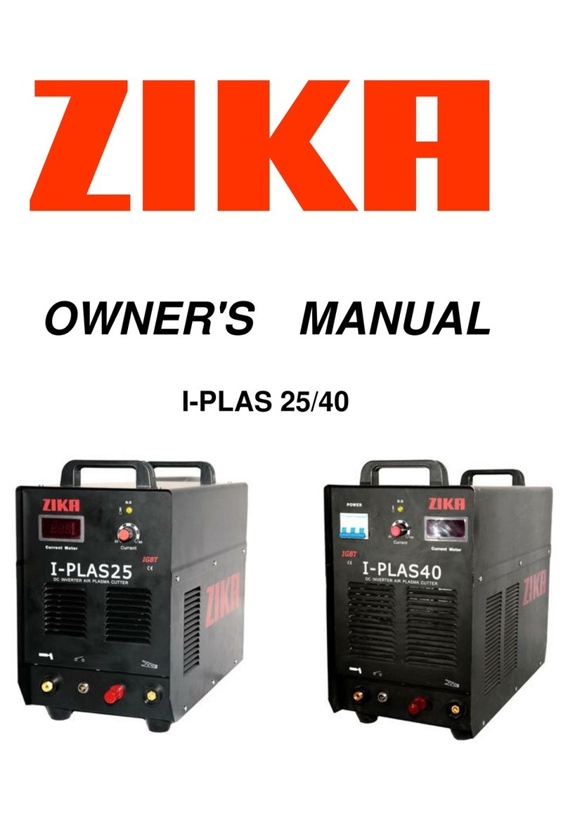
zika I-PLAS60 User manual


FORWARD
Thank you for choosing I-PLAS60 inverter cutter. In order to ensure your safety and correct
operation, please read this manual carefully before operation. Keep this manual properly for
future references.
This product is designed and manufactured according to relevant national and international
standards, and meets GB15579, ICE60974, EN60974, AS60974 and UL60974 standard. This
product conforms to the EMC requirements for Class-A devices. Relevant design plans and
manufacturing technologies of this product are patented.
Version: A0
Code: 10047682

SAFETY
Precautions for installation
Beware of electric shock!
Install grounding device according to application standard.
Do not touch live parts with naked skin, wet gloves or wet
clothes.
Be sure you are insulated from ground and workpiece.
Cover the cover plate of the machine before power on to
avoid an electric shock.
Confirm the safety of your working position.
Beware of fire hazard!
Please install the machine on non-combustible materials to
avoid a fire.
Make ensure there are no inflammables near the cutting
position to avoid a fire.
Beware of explosion!
Do not install the machine in an environment with explosive
gas to avoid an explosion.
Replacing the components can be dangerous.
Only professionals can replace the components of the machine.
Make sure there are no foreign bodies such as wire leads, screws, gaskets and metal bars
falling into the machine inside when replacing the components.
Make sure the connecting wires inside the machine are correctly connected after replacing
the PCBs, and then the machine can be run. Otherwise, there is a risk of damage to
property.
Carrying or moving the machine can be dangerous.
Cut the input power off via the switching box before moving the cutting machine.
The handle can only be used for moving the cutting machine by hand in short distance, and
it cannot be used for lifting. Otherwise, personal injury or property damage may be caused
by a drop.
Make sure that the flying rings are tightened, and that the machine enclosure and cover are
fixed when moving the cutting machine with a crane,
Two lifting belts should be used when lifting the cutting machine, and the angle formed by
the lifting belt and the vertical should be smaller than 15°.

Do not apply any stress on the operation panel and cover when moving the cutting machine.
Otherwise, personal injury or property damage may be caused by a drop.
Do not install and run the cutting machine when the machine is damaged or lacks any
components. Otherwise, fire hazard or personal injury may be caused.
Precautions for operation
Protect yourself and others during cutting, and keep children away from the cutting site.
Make sure that all installation, operation, maintenance and repair work are carried out by
qualified individuals.
Professional training is needed before operating the machine.
Use labor protection welding supplies authorized by national
security supervision department.
Operators should be with valid work permits for metal welding
(cutting) operations.
Cut off power before maintenance or repair.
Arc radiation-may hurt your eyes and burns your skin!
Use proper mask and wear protective clothing to protect your eyes
and body.
Use proper mask or curtain to protect onlooker from being injured.
Warn others not to look straight into arc with signs.
Smoke-may be harmful to your health!
Keep your head away from the smoke to avoid inhalation of waste
gas in cutting.
Keep the working environment well ventilated with exhaust or
ventilation equipment when cutting.
Magnetic field can make cardiac pacemaker a bit wonky.
People with cardiac pacemaker should consult the doctor before
carrying out cutting.
Avoid winding the cutting torch cable or cutting cable around your
body to reduce the affect of magnetic filed
Stay away from the powersource.
Improper use and operation may result in a fire or an explosion.
Cutting spark may result in a fire, so please make ensure there are no
inflammables 10m around the cutting position, and pay attention to
fire safety.
Ensure there is fire extinguisher nearby, and make sure someone has
been trained to operate the fire extinguisher.

Do not cut closed container.
Plasma arc may damage the frozen pipe.
Do not use this machine for pipe thawing.
Plasma arc may cause injuries and burns.
Be away from the nozzle of the cutting torch, for the plasma arc
would cut your gloves and skin quickly.
Do not hold the metal near the cutting path.
Never point thecutting torch to yourself or to anyone else.
Excessive noise does great harm to people’s hearing.
Wear ear covers or other hearing protectors when cutting.
Give warning to onlooker that noise may be potentially hazardous to
hearing.
Moving parts may injure your body.
Please keep away from moving parts (like fan).
Each door, panel, cover, baffle plate, and protective device the like
should be closed and located correctly.
Static may damage the circuit board.
Store the circuit board in antistatic containers.
Please wear grounded wrist strap when processing circuit board.
Pay attention to the safety of the compressed gas equipment.
Never lubricate the high-pressure cylinder valve or regulator with oil
or grease.
Only the correct cylinder, regulator, hose and installation accessories
designed for specialpurposes can be used.
Ensure that all compressed gas equipment and related parts are in
good working condition.
Mark all gas hoseswith labels and color codes to clearly identify the
type of gas inside the hoses.
Seek professional support when trouble strikes.
When trouble strikes in installation and operation, please inspect
according to related contents in this manual.
If you still cannot understand fully, or you still cannot solve the
problem, please contact the dealer or the service center to obtain
professional support.

Precautions for discard
Pay attention to the following when discarding the cutting machine:
Burning the electrolytic capacitors in the main circuit or on the PCBs may cause an
explosion.
Burning the plastic parts such as the front panel may produce poisonous gas.
Dispose it as industrial waste.
TABLE OF CONTENTS
1. GENERAL DESCRIPTION ......................................................................................................8
1.2 Technical parameters..........................................................................................................8
1.3 Size and weight...................................................................................................................9
1.4 Composition and configuration of the cutting machine system.....................................10
1.5 Functions and characteristics of the cutting machine.....................................................12
1.6 System characteristics ......................................................................................................12
2. INSTALLATION AND CONNECTION..................................................................................... 13
2.1 Installation requirements.................................................................................................13
2.2 Electrical connection ........................................................................................................14
2.3 Connection of the air supply device ................................................................................16
2.4 Installation of the cutting torch .......................................................................................17
3. OPERATION...................................................................................................................... 18
3.1 Panel functions of I-PLAS60 ..........................................................................................18
3.2 Function of the components............................................................................................20
3.3 Operation of the cutting machine....................................................................................21
3.4 Connection of the work clamp.........................................................................................22
3.5 Adjustment of the pilot arc gas........................................................................................23
3.6 Handheld cutting torch operation ...................................................................................23
3.7 Automatic cutting of the cutting torch ............................................................................26
3.8 Cutting parameters table .................................................................................................29
3.9 Obtaining the original arc voltage....................................................................................31
4. MAINTENANCE................................................................................................................. 31
4.1 Daily maintenance............................................................................................................31
4.2 Periodic check...................................................................................................................33
5. TROUBLESHOOTING ......................................................................................................... 35
5.1 Troubleshooting of the cutting machine..........................................................................35
5.2 Replacing the gas filter element ......................................................................................37

1. GENERAL DESCRIPTION
1.1 Technical parameters
Table 1-1: General technical parameters
Items
Model
I-PLAS60
Input
Rated input power supply
Three-phase AC 380V±15% 50Hz
Rated input capacity (KVA)
29.2
Power factor
0.93
Cutter
output
Rated no-load voltage (V)
330
Rated maximum output (A/V)
160/144
Cutting current range (A)
30~160
Output characteristic
CC
Arc ignition mode
Non-contact
Quality cutting thickness (mm)
40 (carbon steel)
Maximum cutting thickness (mm)
60 (carbon steel)
Recommended compressor capacity (L/min)
170
Recommended cutting pressure (Kg/cm2)
4~6
Environment
Working temperature range (℃)
-10~+40
Storage temperature range (℃)
-25~+55
Humidity (%)
≤90% (no water condense)
Structure
Enclosure ingress protection
IP21S
Cooling mode
Forced air cooling
Rated duty cycle (%)
60
Efficiency (%)
85
Insulation grade
F

1.3 Size and weight
Table 1-2: Overall size and weight of the machine
Model
I-PLAS60
Overall size (L*W*H)(mm)
676*333*712
Weight (Kg)
55
Figure 1-2: Appearance and size of the machine (Unit: mm)

1.4 Composition and configuration of the cutting machine system
1) Composition of the cutting system
Figure 1-3: Composition of the cutting machine system
2) Configuration of the cutting power source
Table 1-3: Configuration of I-PLAS60
Name
Material code
Specification
Quantity (pcs)
Remark
Cutting machine
10046193
I-PLAS60
1
Standard configuration
Cutting torch
10034559
A141 (6m)+2-pin aviation plug
1
Standard configuration
Earth clamp
10003274
300A-25mm2-DKJ35-50 (3m)
1
Standard configuration
Gas hose
10041278
Φ10 PU hose 8*10 (3m) (blue)
1
Standard configuration
Nozzle
10019737
PD0101-1.7A141 (ROHS )
4
Standard configuration
Electrode
10019729
A141 (ROHS)
4
Standard configuration
Hoop
10016387
--
4
Standard configuration

3) Composition of the cutting torch
Figure 1-4: Composition of the cutting torch
4) Configuration of the cutting torch
Table 1-3: Configuration of I-PLAS60
Name
Material code
Specification
Quantity (pcs)
Remark
Cutting torch
10019668
A141 (6m)
1
Standard configuration
2-pin aviation plug
10004659
2-pin (WS16J2TQ)
1
Standard configuration
Wire lug
10011017
OT6-8
1
Standard configuration
Nozzle
10019737
PD0101-1.7A141 (ROHS )
1
Standard configuration
Swirl ring
10030218
A101/A141 (PE0101)
1
Standard configuration
Electrode
10019729
A141 (ROHS)
1
Standard configuration
1/4G adapter
10016394
M16*1.5
1
Standard configuration

1.5 Functions and characteristics of the cutting machine
Features
The machine adopts advanced inverter technology. High inverter frequency of 20 KHz greatly
reduces the volume and weight of the cutter.
Great reduction in magnetic and resistance loss obviously enhances the cutting efficiency
and energy saving effect.
Closed loop feedback control, stable output cutting current, workable under mains voltage
fluctuation within ±15%.
Non-contact ignition with pilot arc, excellent arc ignition, can cut rusty and painted metals
conveniently.
Excellent dynamic characteristics, high arc stiffness, smooth cutting surface, high cutting
performance.
Current upslope function is available when arc is ignited to carry out cutting, which can
reduce the arc ignition impact. Beside, the constant pilot arc technology can effectively
prolong the lifespan of the electrode and nozzle of the cutting torch.
The cutting current can be accurately preset and stepless adjustment can be achieved
through the preset current function. Thus, the machine is can be used to cut workpiece with
different thickness. Low current is used when cutting thin plate and high current is used
when cutting thick plate to ensure cutting quality and save energy.
With protection function of over/under-voltage, overheating and low gas pressure inside
the machine; gas-check and 2T/4T function available; arc establishing signal and arc voltage
output signal optional; convenient to connect all kinds of CNC machine tools.
Adopting main components of world’s top brands, with high reliability.
Application
Economic and practical by adopting compressed air as the plasma gas source. The plasma
cutter has a wide range of use, especially for cutting metal plates of carbon steel, alloy steel,
stainless steel, galvanized steel, copper and aluminum, etc.
It can be widely in various industries involving metal cutting such as boiler and pressure
vessel manufacturing, chemical container manufacturing, power plant installation and
construction industry, metallurgy, chemical engineering, aerospace, automobile and
engineering vehicles manufacturing and construction, etc.
1.6 System characteristics
1) Duty cycle
Rated duty cycle refers to the percentage of the normal work time of the machine under rated
maximum current holding in the period when taking 10 minutes as a period and the
environmenttemperature is 40℃.The rated duty cycle of this machine is 60%. That is to say,
under the working current of 160A, the plasma arc can work for 6 minutes continuously in a
10-minute period without leading to overheating of the machine. Using the cutting machine

continuouslyoverrunning the rated load may lead to overheating of the machine and frequently
using the machine overrunning the rated load may accelerate the aging of the machine or even
burn the machine.
Figure 1-4: Duty cycle
2) Output characteristics
Figure 1-5: Output characteristic curves
2. INSTALLATION AND CONNECTION
2.1 Installation requirements
1) Environment requirements
a) Do not install the machine at places with excessive dusts and metal powders.
b) Do not install the machine at places with corrosive or explosive gas.
c) The temperature of the working environment should be between -10℃and 40℃.
d) Do not carry out cutting with the cutting machine placed on a platform with a pitch greater
than 15°.
e) The machine should be installed in a well-ventilated place with humidity of 90% or less and
without water condense.
f) Pay attention to the wind at the cutting site, and use wind deflector if necessary. Otherwise,

the cutting process will be affected.
2) Installation space requirements
The cutting machine should be at least 20cm away from the walls, and there should be at least
30cm between them when two machines are installed side by side. Please refer to the table
below to determine the installation position of the cutting machine.
Table 2-1: Reserved space when installing the cutting machine
Machine part
Front
Top
Left
Right
Rear
Reserved space
≥20cm
≥10cm
≥20cm
≥20cm
≥20cm
2.2 Electrical connection
1) Installation of the input power supply for the cutter
The maximum output voltage varies with the input voltage and the current of the circuit.
Because the source current may fluctuate in the process of start, it is recommended to use
slow-blow fuse for it can withstand current 10 times the rated value for a short time.
WARNING: Use slow-blow fuse and power disconnect switch to protect the circuit.
Model
Input voltage
Phase
Rated output
Input current (when the
output power is 23KW)
Recommended
fuse capacity
I-PLAS60
330~450V AC
Three-phase
160A, 144V
50A
100A
* For applications requiring long arc, please use high-current fuse.
Connection of switching box
Figure 2-1
1. Power switch of the switching box
2. Fuse (100A)
3. Input power cord of the cutting machine (4*6mm2)
4. Yellow-green earth wire (earth, not connect to the null line)
Connect according to the figure on the left or in other correct ways.
Cut off the main power before connection.
Note: No operation with power on.
Ask professional electrician to do the connection.
Do not connect two cutting machines to the same switching
box.
Wire 4 is unnecessary to be grounded if the enclosure is grounded.
Installation of the disconnect switch
A disconnect switch should be installed for each power supply, so that the operator can quickly
cut off the power supply in an emergency. The switch should be installed in a position the
operator can easily reach. The installation should be carried out by qualified electrician according
to the national and local laws and regulations.

The cut-off value of the switch should be equal to or greater than the continuous rated value of
the fuse. In addition, the switch should have the following features:
It can disconnect the electrical appliances from the input voltage and cut off the connection
of all electric conductors when the switch is in “OFF”position.
It has an “OFF”position and an “ON”position, which is clearly marked with “0”and “1”
respectively.
It has an external operating handle, which can be locked in “OFF”position.
It contains an electric operation device used as an emergency shutdown device.
It has a slow-blow fuse with the specification as described in the above table.
Provisions on grounding
In order to operate the system correctly and reduce the electromagnetic interference (EMI) on
the premise of ensuring the personal safety, the cutting machine I-PLAS60 should be reliably
grounded.
Ground the power supply through the power cord according to the national and local
electrical regulations.
Three-phase power supply should be equipped with a 4-wire power cord (the green wire or
yellow-green wire is for grounding purpose) and should be in accordance with the relevant
national and local regulations.
For more details, please refer to the “safety”section.
Precautions for the power cord
No plug is attached to the power cord of the power supply of the cutting machine I-PLAS60.
Please purchase the correct plug (380V) according to the device you use and your region, and
then ask qualified electrician to carry out the installation.
Recommended specification for the prolonged cable
The diameter size of the prolonged cable should be commensurate with the cable length and the
system voltage. Please use cablesin accordance with the relevant national and local regulations.
The table below lists the recommended diameter sizes for different cable length and input
voltage. The cable length listed in the table refers to the length of the prolonged cable only, with
the length of the power cord of the power supply itself exclusive.
Table 2-2: Recommended specification for the prolonged cable
Input voltage
Phase
<3m
3~7.5m
7.5~15m
15~30m
30~45m
380V AC
Three-phase
6mm2
8mm2
8mm2
10mm2
10mm2
2) Specification of the input power supply for the cutter
Table 2-3: Specification of the input power supply for the cutter
Items
Specifications
I-PLAS60
Power supply characteristic
Mains power supply
23KVA

Input protection device (Switching box)
Air switch
>100A
Cable
Input side of the cutter
≥6mm2
Output side of the cutter
≥25mm2
Earth cable
≥cable on the input side
The generator used by I-PLAS60 should be able to produce nominal voltage of 380V AC, and its
power is recommended to be higher than 50KW.
Note: Please adjust the cutting current to the desired value according to the rated power,
lifespan and working condition of the generator.
If a failure occurs when using the generator, turn the power switch quickly to “OFF”position and
back to “ON”position (sometimes it is called “quick reset”). If the problem cannot be solved,
shut off the power, wait for 30~45 seconds, and then switch the power on.
2.3 Connection of the air supply device
1) Preparation for the air supply device
The cutting machine I-PLAS60 can adopt either the factory pressurized air supply device or the
cylinderpressurized air supply device. Both kinds of air supply device should adopt high pressure
regulator, and should be able to transmit the air to the filter on the power supply under the air
flow of 170L/min and the air pressure of 6.2Kg/cm2.
WARNING
The air pressure should not be higher than 9.3Kg/cm2, and the filter would explode if the air
pressure is overly high.
If the quality of air is poor, the cutting speed will decrease, the cutting quality willlower, the
cutting thickness will reduce, and the service life of wearing parts will be shortened. In order to
obtain the optimal performance, the maximum particle size of air should be 0.1μm, the
maximum concentration of air should be 0.1mg/m3, the maximum dew point of air should be
-40℃, the maximum oil concentration should be 0.1mg/m3.
2) Connection of the air supply device
Connect the air supply device to the power supply by using a blue hose (Φ 10) and a quick gas
connector, as shown in Figure 2-2.

Figure 2-2 Connection of the gas hose
3) Adding air filtration device
If there is water or oil in the air or there is other contaminants going into the gas circuit, please
use the three-stage filtration system to remove the pollutants in the air supply device through
the method shown below.
2.4 Installation of the cutting torch
1) Introduction of the cutting torch
The plasma cutter I-PLAS60 adopts A141 cutting torch for its standard configuration.
The frequency of replacing the wearing parts of the cutting torch depends on the aspects below:
The thickness of the metal to be cut.
The average cutting length.
Whether it is used for automatic cutting or it is used for handheld cutting.
Air quality (whether there is oil, water or other contaminants)
Whether it is used to punch on the metal or it is used to cut from the metal edge.
Whether the distance between the cutting torch and the workpiece is appropriate when
cutting with wearing parts without protective sleeves.
Whether the cutting height is appropriate.
The quality of the wearing parts used.
Under normal circumstances, the nozzle runs out firstly in hand-held cutting.
The general rule is: The wearing parts will run out after the practical “arc discharge”time reaches
1~2 hours when it is used for handheld cutting. The specific time depends on the above factors.
The wearing parts will run out after the practical “arc discharge”time reaches 3~5 hours when it
is used for automatic cutting. For more information on the correct cutting method, please refer

to the"operation" chapter.
2) Installation of the cutting torch
Selecting wearing parts
A complete set of wearing parts for cutting are attached to the cutting torch A141, including the
wearing parts installed on the cutting torch and the spare electrodes and nozzles contained in
the wearing parts package.
Standard wearing parts for cutting torch A141 are recommended in order to obtain optimal
cutting quality.
3) Installation of the wearing parts
WARNING: Plasma arc may cause burns or scalds during the
instantaneous start of cutting torch.
Plasma arc will be produced at the moment after the cutting torch is started,
so make sure that the power is cut off before replacing the wearing parts.
Turn the power switch to “OFF”position, install the complete set of wearing parts of the cutting
torch, including the fixing frame, fixing cover, nozzle, swirl ring and electrode, according to the
figure below.
Figure 2-3: Wearing parts of the cutting torch
3. OPERATION
3.1 Panel functions of I-PLAS60

Figure 3-1: Front panel of I-PLAS60
No.
Part name
Function
1
Lifting ring
For lifting the machine.
2
Handle
For carrying the machine
3
Abnormity indicator
To indicate the machine is under overcurrent or overheating
protection status when it illuminates.
4
Digital meter
To display the cutting current.
5
Gas lack indicator
To indicate that the supply gas pressure is insufficient (<0.3MPa)
6
Gas pressure meter
To display the current gas pressure during the machine is working.
7
Gas-check switch
To switch among plasma air checking, working gas checking and
cutting.
8
2T/4T switch
To switch between 2T and 4T cutting mode.
9
Gas pressure control knob
To adjust the gas pressure during the machine is working.
10
Current control knob
To adjust the cutting current value.
11
Interface for the cutting torch
To connect the cutting torch.
12
Pilot arc terminal
To connect the pilot arc wire lug of the cutting torch.
13
Quick socket
To connect the earth clamp.
14
2-pin aviation socket
To connect the 2-pin aviation plug of the cutting torch; to control
the start-up of the machine.
15
Swivel caster
To support the machine; for moving the machine.

Figure 3-2: Back panel of I-PLAS60
No.
Part name
Function
1
Power switch
To control the ON/OFF of the input power of the machine.
2
Air reducer valve
To adjust the pressure of the input air.
3
Cooling fan
For heat dissipation through forced air cooling.
4
Cable
For power supply input.
5
Fuse holder
Tomount the fuse
3.2 Function of the components
Pilot arc terminal
The pilot arc terminal is the interface for the pilot arc wire lug of the cutting torch to connect the
machine. If it needs to connect the pilot arc wire lug of the cutting torch, rotate this terminal
counterclockwise to remove the cap, fix the wire lug, and then fix the cap back.
Interface for the cutting torch
This interface is with protective function, so electric shock caused by accidental touch of the
interface during working can be avoided.
2-pin aviation socket
The 2-pin aviation socket connects the control circuit. The control signal from the cutting torch
controls the start-up and stop of the machine through this aviation socket.
Quick socket
With this socket, the quick plug with work clamp can be installed and removed conveniently.
Fuse holder
When the input current is overly high and reaches a certain value, the fuse will break
automatically, the control circuit of the cutting machine will stop working, and the main circuit
will stop working consequently to protect the cutting machine from damage.
Filter
Table of contents
Other zika Welding System manuals

zika
zika I-PLAS 25 User manual

zika
zika TIG160S User manual

zika
zika I-PLAS25 II User manual

zika
zika Mini 160 User manual

zika
zika I-DC 400 User manual

zika
zika MIG500 User manual

zika
zika I-TIG 200AC/DC II User manual

zika
zika MIG 200G User manual

zika
zika MIG300GD User manual

zika
zika I-TIG200DC User manual
Popular Welding System manuals by other brands

Eastwood
Eastwood MP200i Assembly and operating instructions

Lincoln Electric
Lincoln Electric LF 52D Operator's manual

GYS
GYS TIG 220 AC/DC manual

Miller
Miller Axcess E 300 owner's manual

Lincoln Electric
Lincoln Electric BIG RED 500 Operator's manual

Lincoln Electric
Lincoln Electric POWER MIG 256 Operator's manual