zika MIG300GD User manual

MIG 300GD WLEDING MACHINE
USER MANUAL

Preface
This manual includes hardware description and operation introduction of MIG 300GD equipment. For
your and other people’s safety, please read the manual carefully.
Pay attention
Pay attention to the words after the signs below.
Sign
Description
The words after this sign means there is great potential danger,
which may cause major accident, damage or even death, if it is not
followed.
The words after this sign means there is some potential danger,
which may cause hurt or property lose, if it is not followed.
The words after this sign means there is potential risk, which may
cause equipment fault or break, if it is not followed.
Version
Version YF-41H, A1, Released at 19th, 7, 2012.
The contents of this manual are updated irregularityfor updating of product. The manual is only used
as operation guide, except for other promises. No warranties of any kind, either express or implied
are made in relation to the description, information or suggestion or any other contents of the
manual.

3
CONTENTS
1 SATETYWARNING........................................................................................................................ 4
2 Product.......................................................................................................................................... 10
2.1 General ................................................................................................................................. 10
2.2 Technical data ........................................................................................................................11
3 Installation..................................................................................................................................... 12
4 Operation ...................................................................................................................................... 15
4.1 Front panel layout ................................................................................................................. 15
4.2 Operation instruction ............................................................................................................ 16
4.3 Welding environment and safety .......................................................................................... 22
4.4 Welding problems and resolution ......................................................................................... 23
5 Daily maintenance and checking .................................................................................................. 24
6 Trouble shooting and fault finding................................................................................................. 28
Appendix Welding parameter list .................................................................................................. 32
Appendix Circuit diagram .............................................................................................................. 35
Appendix Components figure and list ........................................................................................... 36

4
1 SATETY WARNING
The safety notes listed in this manual is to ensure correct use of the machine and to keep you
and other people from being hurt.
The design and manufacture of welding machine considers safety. Please refer to the safety
warning listed in the manual to avoid accidents.
Different damage would be caused by wrong operation of the equipment as follows. Please
read the user manual carefully to reduce such damage.
Sign
Description
Any contact of electric parts may cause fatal electric shock or burnt.
Gas and fumes are harmful to health.
Operation in narrow space may cause choke .
Spark and hot workpiece after welding may cause fire.
Bad connected cable may cause fire.
Incompletion connection of workpiece side circuit may cause fire.
Never weld on the case of tinder stuff, or it may cause explode.
Never weld airtight containers such as slot, pipe etc., or it may break.
Arc ray may cause eye inflammation or skin burnt.
Spark and residue will burn your eyes and skin.
Toppling over of the gas cylinder will cause body hurt.
Wrong use of the gas cylinder will lead to high-pressure gas eruption
and cause human hurt.
Never let fingers, hair, clothes or etc. near the moving parts such as
the fan.
The wire shoot out of the torch may stab eyes, face and other naked
parts.
Never stand in front of the swang equipment or under it, or it may fail
and cause injury.

5
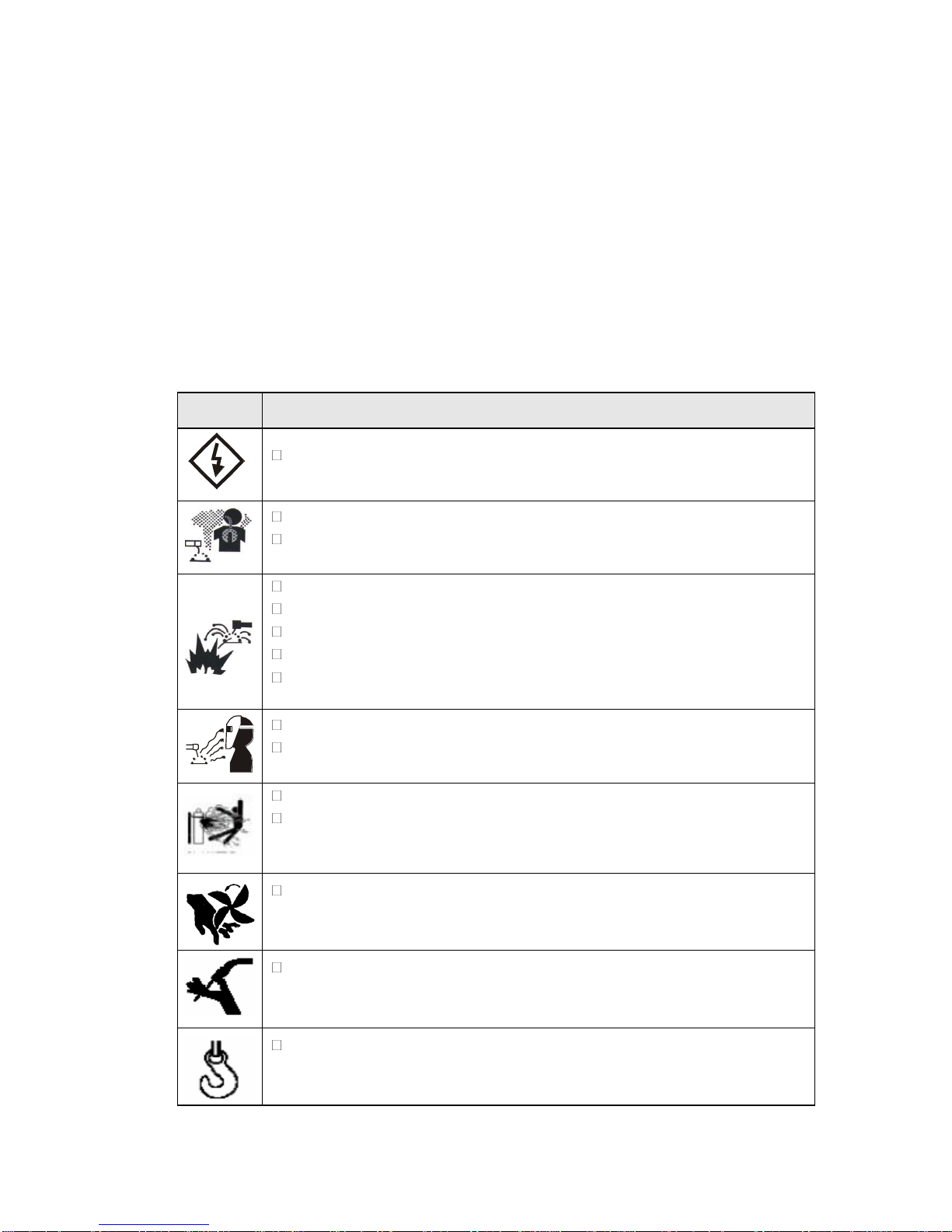
Please follow the rules below to avoid heavy accidents.
●
Never use the equipment to do other things but welding.
●
Follow related regulations for the construction of the input-driven power source, choice of
place, usage of high-pressure gas, storage, configuration, safe-keeping of workpiece after
welding and disposal of waste, etc.
●
Nonessentials do not enter the welding area.
●
People using heart pacemaker is not allowed to get close to the welding machine or area
without doctor’s permission. The magnetism created by energizing the welding machine
can have a bad effect to the pacemaker.
●
Install, operation, check and maintain the equipment by profession personnel.
●
Understanding the contents of the user manual for safety.
Please follow the rules below to avoid electric shock
●
Keep away from any electric parts.
●
Earth the machine and workpiece by professional personnel.
●
Cut off the power before installation or checking, and restart 5 minutes later. The
capacitance is chargeable device. Please ensure it has no voltage before start again even if
the power source is cut off.
●
Do not use wire with inadequate section surface or damage insulation sleeve or even
exposed conductor.
●
Do ensure well isolation of wire connection.
●
Never use the device when the enclosure is removed.
●
Never use broken or wet insulation gloves.
●
Use firenet when work at high position.
●
Check and maintain regularly, don’t use it until the broken parts are fixed well.
●
Turn off the power when not in used.
●
Follow the national or local related standard and regulations when using the AC welding
machine at narrow or high position.
Please follow the below notes to avoid fire and explode, etc.
●
No combustible in welding area.
●
Keep off combustible when welding.
●
Keep hot workpiece after welding away from flammable gas.
●
Do move away the combustible around when weld the dooryard, ground and wall,.
●
The wire connection of base metal should be as close to the welding place as possible.
●
Never weld those facilities with gas pipe or airtight slot.
●
Put fire extinguisher around the welding area to prevent fire.

6
The gas and fumes are harmful to health, please wear protective
device according to regulations.
●Wear exhaust equipment and breathe preventive facilities to prevent gas poisoning or
choke.
●Use suggested part exhaust equipment and breathe preventive facilities to prevent hurt or
poisoning by gas and other powder, please.
●To prevent oxygen-deficiency, air out the gas-filled room which is full of CO2 and argon on
the bottom, When operating on trunks, boilers, cabins, etc.
●Please accept the supervisor’s inspection when operating in narrow space. Air the room
and wear breathe preventive facilities.
●Never operate in degrease, washing or spray space.
●Using breathe preventive facilities when weld shielded steel for it will cause poisonous dust
and gas.
The arc, spark, residue and noise are harmful to health, please wear
protective appliance.
●Eye protection against arc is recommended when welding or supervise welding.
●Please wear preventive spectacles.
●Welder’s gloves, welder’s goggles, long sleeve clothes, leather apron, and other standard
protection equipments must be worn for welding operation.
●A screen to protect other people against the arc must be set in the welding place.
broken. Please follow the notes below to avoid gas cylinder toppling over or
●Use the gas cylinder correctly.
●Use the equipped or recommended gaseous regulator.
●Read the manual of gaseous regulator carefully before using it, and pay attention to the
safety notes.
●Fix the gas cylinder with appropriative holder and other relative parts.
●Never put the cylinder under high temperature or sunshine environment.
●Keep your face away from the gas cylinder exit when opening it.
●Put on the gas shield when it is not used.
●Never put the torch on the gas cylinder. The electrode can not meet the gas cylinder.

7
following. Any touch of the switch part will cause injury, please note the
●
Never use the machine when the enclosure is off.
●
Install, operate, check and maintain the machine by professional person.
●
Keep your fingers, hair, clothes etc. away from the switch parts such as the fan.
The wire end may deal damage, please note the following.
●
Never look into the electric conduction hole when checking the wire feeding is normal or
not, , or the shooting wire may stab your eyes and face.
●Keep your eyes,face or other naked parts away from the end of torch when feeding the wire
manually or pressing the switch.
For better work efficiency and power source maintenance, please
note the following.
●Precautions against toppling over.
●Never use the welding equipment for pipe thawing.
●Lift the power source from side when use the up-down forklift truck to avoid toppling over.
●When using the crane for lift, tie the rope to the ears with an angle no more than φ15 to the
vertical direction.
●When lifting the welding machine which equipped with gas cylinder and wire feeder,
download them from the power source and ensure the horizontal of the machine. Do fix the
gas cylinder with belt or chain when moving it to avoid body hurt.
●Ensure fastness and insulation when lifting the wire feeder through the swing ring for
welding.

8
Correct False
Lifting way for gas shielded machines
Electromagnetic interference needing attention:
●It may need extra preventive measures when the equipment is used in particular location.
●Before the installation, please estimate the potential electromagnetism problems of the
environment as follows.
a)Upper and lower parts of the welding equipments and other nearby power cable, control
cable, signal cable and phone cable.
b) Wireless electric as well as TV radiation and reception equipment.
c) Computer and other control equipments.
d) Safety-recognition equipment etc. Such as supervise of industrial equipments.
e) Health of people around. Such as personnel using the heart pacemaker or audiphone.
f) Equipments for adjustment and measurement.
g)Anti-disturb capability of other used equipments .Users should ensure these equipments
and the environment are compatible, which may need extra preventive measures.
h) Practical state of the welding and other activities.

9
●Users should observe the following dos and don’ts to decrease radiation interference.
a) Connect the welding equipments to the power supply lines.
b) Maintain the welding equipments regularly.
c) The cable should be short enough to be close to each other and the ground.
d) Ensure the safety of all the welding metal parts and other parts nearby.
e) The workpiece should be well earth.
f) Shield or protect the other cable and equipments to decrease the effects of disturbances.
The welding equipments can be complete shielded in some special conditions.
●Users are responsible for interference due to welding.

10
2 Product
2.1 General
The welding machine applies the most advanced inversion technology in the world.
The principle of inversion is to transform the power frequency of 50Hz/60Hz into direct current
and invert it into high frequency (24KHz) through high-power device IGBT, then perform
voltage-drop and commutation with the output high-power D.C power supply via Pulse Width
Modulation (PWM). Since the switch power inversion technology is adopted, the weight and
volume decrease greatly while the conversion efficiency increase of more than 30%
Additional to MIG, the machine added MMA function. It adopts full digital panel display, which
can realize synergic adjustment of feeding speed and welding voltage as well to regulate the
welding parameters easily.
Our CO2 gas shielded welding machine is equipped with unique electronic reactor circuit, which
can precisely control the short-circuiting transfer and mixed transfer resulted in better
performance than other machines. Compared with silicon controlled welding machine and
tapped welding, our products have the following advantages: stable wire feed rate, portable,
energy-saving, electromagnetic noise free. Besides, our products spatter less, easier arc
starting, deep welding pool, high duty cycle etc.
With high-efficiency and electrical-saving advantage, this equipment is applicable for both
multi-metal and mutli-technology required welding.
Thank your for choosing our products. Please feel free to propose your valuable suggestions;
we will make efforts to perfect our products and service.
The machine is mainly used in industrial fields. It will cause radion interference if used
indoors. Please take through precaution measures.

11
2.2 Technical data
Type
Item
MIG 300GD
Power voltage (V)
3 phase
380V 15%
Frequency (Hz)
50/60
Rated input current (A)
MMA 18.5
MIG 16.8
Output current adjustment (A)
MMA 40-300
MIG 45-300
Output voltage (V)
MMA21.6-32
MIG 16.2-29
Duty cycle (%)
35
Power factor
0.93
Efficiency (%)
85
Type of wire feeder
Internal
Wire feed speed (m/min)
2.2-15
Post flow time (S)
3
Welding-wire diameter (mm)
0.8/1.0/1.2
Insulation grade
F
Housing protection grade
IP21
Welding thickness (mm)
More than 0.8
Weight (kg)
60
Overall dimension (mm)
595*275*520

12
3 Installation
The welding equipment is equipped with power voltage compensation device. It keeps the
machine work normally when power voltage fluctuating ±15% of rated voltage.
When using long cable, in order to reduce voltage drop, big section cable is suggested. If the
cable is too long, it will affect the performance of arcing and other system function, it is
suggested to use the recommend length.
Make sure the intake of the machine is not covered or blocked to avoid the malfunction of
the cooling system.
Use ground cable whose section no less than 6mm2 to connect the housing and earth. The
method is to connect the grounded interface in the back to the earth device, or make sure
the earth end of power interface has been reliably and independently grounded. Both ways
can be used together for better security.
MIG 300GD Installation Procedures
Correct Installation of MIG
a) Connect the gas cylinder with CO2 decompression flow mete tightly to CO2 mouth behind
the machine via air tube.
b) Insert the swift plug of earth cable into socket at the front panel.
c) Set the wire wheel with wire on the wheel axis, the wheel hole should be matched with the
wheel fixer.
d) Choose wire slot according to wire size.
e) Loosen the screw of wire-pressing wheel, pit the wire into slot via wire-lead tube, adjust the
wire-pressing wheel to keep wire fix from gliding, but strength should be suitable in case the
wire distorts and affects wire sending.
f) Wire roll should turn clockwise rotation to let out wire, to prevent wire from gliding; wire is
usually set to the fixed hole on the wheel side. To prevent the bent wire from getting stuck,
please cut off this part of the wire.
g) Put and tighten the torch on the output socket and put the wire into the torch by hand.
h) Put the heater plug of the gas meter to the heater socket on the back panel.
Correct Installation of MMA
a) Make sure cable with electrode holder and quick plug connected well. Connect the quick
plug to the socket “-”of the machine, and fasten it clockwise tightly.
b) Connect the quick plug at one end of the cable into the socket “+”of the machine, and
fasten it clockwise, the other end clamps the workpiece.
c) Please pay attention to the connecting terminal, DC welding machine has two connecting

13
ways: positive connection and negative connection. Positive connection: holder connects
with “-”terminal, while work piece with the “+”terminal. Negative connection: work piece
with the“-”terminal, holder with the “+”terminal. Choose suitable way according to the
working situation. If unsuitable choice is made, it will cause unstable arc, more spatters and
conglutination. If such problems occur, please change the polarity of the fastened plug. It
should adopt negative connection when welding with alkaline electrode, while positive
connection when welding with acid electrode.
This procedure shall be operated by electrician!
Connect proper power cable to the distribution box with corresponding capacity according to the
input voltage and current (See technical parameter table). Do not connect to the inappropriate
voltage and make sure that the difference of power supply is within permitted range.

14
Installation drawing of MIG 300GD (MIG):
Installation drawing of MIG 300GD (MMA):

15
4 Operation
4.1 Front panel layout
1 9
8
7
2
6
3 5
4
Front panel instruction
1 MMA/MIG switch key
2 VRD/2T/4T switch
key
3 Wire diameter selection key(φ0.8mm φ1.0mm φ1.2mm)
4 Data selection key (effective under MIG mode)
5 Store mode selection key(Memory1 Memory2 Memory3)
6 Multifunctional data adjusting knob coarse adjustment by pressing the knob and turning it:
big regulating rate and high speed; fine adjustment only by turning the knob: small
regulating rate and low speed
7 Gas check

16
8 Multifunctional data
display 9 Burn back
Polarity conversion joint
This machine has the polarity conversion; There are positive output terminal and negative
output terminal between wire feeder and wire spool; When use solid wire with gas protection,
torch socket should be connected to the positive output terminal, ground cable should be
connected to the negative output terminal; When use flux-cored wire, the two connected cable
should be exchanged.
4.2 Operation instruction
4.2.1 Welding display
The starting up display
Switch on the welding power source, the front panel displays as Chart 1. After the
Multifunctional data display (or any key or knob on front panel) flashes for 5 seconds, the
machine enters into the welding mode that saved in the last shutdown.
Chart 1: the starting-up display interface
Operation instruction under MMAmode.
a) When welding stops, Press the STICK/LIFT TIG/MIG switch key the STICK indicator
lights up and it turns into STICK mode.
b) When under STICK mode, pressing the VRD/2T/4T switch key , VRD function is
enabled when the indicator lights up, and displays in multifunctional data display . Or,
the VRD function isn’t enabled if the indicator is off. (Chart 2, Chart 3)

17
Chart 2: under MMAmode, preset current Chart 3: under MMAmode preset current
display with VRD enabled display VRD disabled
c) multifunctional data display shows the preset current“080A”, its unit is ampere(A).
d) Adjusting the Multifunctional data adjusting knob can change the welding current during
welding process, and displayed in multifunctional data display . The welding current
range is 10A-300A.
e) 3 seconds later after setting the welding parameters, the multifunctional data display
would flashes for one time, which means the data has been saved.
f) The panel displays as Chart 4 when perform welding, which means the welding voltage is
23.2V, and the preset current 80A. 5 seconds later, it returns to the preset current state.
Chart4: The display status when welding under MMAmode.
Operation instruction under MIG mode.
a) When welding stops, press MMA/MIG switch key MIG indicator lights up, and the
machine enters into MIG mode.(Chart 5)
b) multifunctional data display shows the preset voltage “18.0V”, its unit is volt(V). while
“05.0m/min means the preset wire feeding speed, its unit is m/min”

18
c) Under MIG mode, pressing BURN BACK ,the indicator lights up, which can realize high
speed wire feeding(Chart 6). multifunctional data display would flash continuously until
pressing the torch switch or any key or knob on the panel. Both multifunctional data
display and BURN BACK stops flashing, and the wire stops feeding.
Chart 5: Preset voltage display under MIG mode Chart 6: Burn back display under MIG mode
d) Under MIG mode, press the Gas check ,the indicator lights up, which can realize gas
check function(chart 7). multifunctional data display would flash continuously until
pressing the torch switch or any key or knob on the panel. Both multifunctional data
display and GAS CHECK stops flashing, and the gas stops checking.
Chart 7: Gas check display under MIG mode
e) Under MIG mode, operate VRD/2T/4T switch key to choose the welding mode. 2T
NORMAL lighting up means 2 step control way: press the torch switch, feed the gas in
advance, and perform welding normally; release the torch switch, burn back and get rid of
the ball on the end of wire, then stop feeding gas 3 seconds later. While, 4T LATCH
lighting up means 4 step control way: press the torch switch for the first time, feed the gas
in advance, and ignite the arc to perform welding; then release the torch switch and
perform welding normally. Press the torch switch for the second time, the welding current

19
attenuates until to crater value and keep on, then release the torch switch again, burn
back and get rid of the ball on the end of wire, then stop feeding gas 3 seconds later.
f) Under MIG mode, operate the wire diameter selection , choose different wire diameter
among φ0.8mm φ1.0mm φ1.2mm
g) Adjust Multifunctional data adjusting knobduring welding can realize the synergic
manipulation of welding voltage and feeding speed, which displays in multifunctional data
display . Theφ0.8mm wire adjustable range is 16.2V 3.0m/min 27V 15.0m/min;φ1.0mm
wire adjustable range is 16.5V 2.2m/min 30.3V 12m/min;φ1.2mm wire adjustable
range is 18.1V 2.2m/min 29.4V 9.0m/min.
h) Press the data selection key for the first time, the multifunctional data display displays
as Chart 8, which means the welding voltage is adjustable, and the adjustment range of
preset voltage is ±20%; Press the data selection key for the second time, the
multifunctional data display displays as Chart 9, which means the inductance is
adjustable, and its adjustment range is ±10%; Press the data selection key for the third
time, it would turn back to preset welding voltage and wire feeding speed.
Chart 8 fine adjustment display of voltage Chart 9 Fine adjustment display of
Inductance presetting range under MIG mode range under MIG mode
i) 3 seconds later after setting the welding parameters, the multifunctional data display
would flashes for one time, which means the data has been saved.
j) The panel displays as Chart 10 when perform welding, whichmeans the welding voltage is
18.2V, and the current is 82A.
k) Releasing the torch switch and stopping welding, the panel displays as Chart 11.
Moreover,“HOLD”flashes for 3 seconds and quenched, which means the welding stops. 2
seconds later, multifunctional data display redisplays the preset current.

20
Chart 10 display status when perform welding under Chart 11 Display status after stop
welding under MIG mode MIG mode
Storage function
Press mode selection , can store 3 modes, which are Memory1,Memory2 and Memory3.
4.2.2 Malfunction display
Malfunction display of wire feeder
The panel displays as Chart 12 when the wire feeder is malfunctioning, and the
multifunctional data display flashes continuously, the machine can not work normally.
Please restart the machine, the panel would display the parameters that were set before
malfunction occurrence.
Malfunction display of over-current
The panel displays as Chart 13 when over-current, and the multifunctional data display
flashes continuously, the machine can not work normally. Restart the machine, the panel
would display the parameters that were set before malfunction occurrence.
Table of contents
Other zika Welding System manuals

zika
zika I-TIG200DC User manual

zika
zika MIG200 User manual

zika
zika I-DC 400 User manual

zika
zika MIG 200G User manual

zika
zika Mini 160 User manual

zika
zika TIG160S User manual

zika
zika I-PLAS 25 User manual

zika
zika I-PLAS25 II User manual

zika
zika I-PLAS60 User manual

zika
zika I-TIG 200AC/DC II User manual