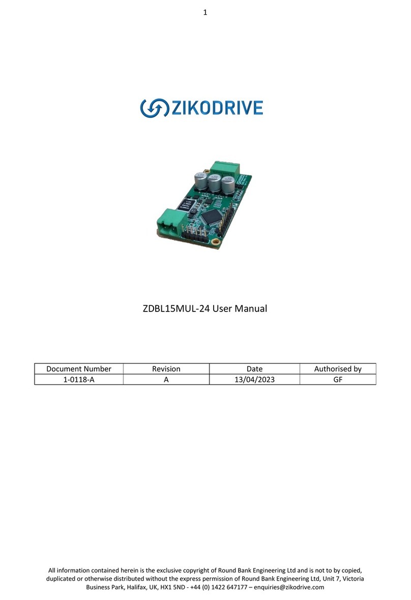
Zikodrive ZD10UART Series User manual

1
Zikodrive Motor Controllers, Unit 4B, Top Land Country Business Park, Cragg Vale, Hebden Bridge, West Yorkshire,
UK, HX7 5RW enquiries@Zikodrive.com –www.Zikodrive.com - +44 (0)333 123 1730
ZikoDrive ZD10UART Series Operating Manual
For Firmware V3.5 and above (dated 10/10/19)
Introduction
OverView
This manual is intended to be used with the ZikoDrive ZD SERIES UART Motor controller running
standard firmware (V3.5 and above) and includes the following UART Commands that can also be
used over RS232 or RS485 using the relevant Break Out Boards:
•Run at a set speed
•Run Number of Microsteps
•Decelerate to Stop
•Emergency Stop
•Move to the Home position
•Reset Home Position
•Move to Absolute Position
•Move to Home input Limit Switch
•Setting STD motor Parameters including Running Current, Holding Current,
Acceleration/Deceleration Current, Acceleration/Deceleration Rates and Microstepping
resolution.
Specifications
•Up to 30Vdc.
•Up to 5A.
•Up to128 Microsteps/Step.
•Modular design connects to many Break Out Boards that can provide options such as
420mA, 0-10Vdc, Optically Isolated inputs, etc...
•Over-temperature protection and stall detection.
•Microprocessor controlled enabling exceptional positional accuracy.

2
Zikodrive Motor Controllers, Unit 4B, Top Land Country Business Park, Cragg Vale, Hebden Bridge, West Yorkshire,
UK, HX7 5RW enquiries@Zikodrive.com –www.Zikodrive.com - +44 (0)333 123 1730
Contents
Contents
Introduction ................................................................................................................................................ 1
Contents.................................................................................................................................................. 2
Board View.............................................................................................................................................. 6
Wiring Motor Phase Wires....................................................................................................................... 7
Power Wires............................................................................................................................................ 7
Connections to Box Header (UART).......................................................................................................... 8
Programming Manual.................................................................................................................................. 9
The UART Protocol................................................................................................................................... 9
The ZikoDrive Protocol ............................................................................................................................ 9
Example 1 –Basic Send........................................................................................................................ 9
CheckSum formula ................................................................................................................................ 10
Command Complete.............................................................................................................................. 11
Example 2 –Command Complete (RUN_STPS)................................................................................... 12
Example 3 –Command Complete (RUN_SPD).................................................................................... 13
Shortlist of Commands .......................................................................................................................... 14
Incremental Commands ............................................................................................................................ 15
RUN_SPD (0x01) .................................................................................................................................... 15
RUN_SPD Formula ............................................................................................................................. 16
Example 4 -RUN_SPD (Multiple Commands)................................................................................. 16
RUN_STPS (0x02)................................................................................................................................... 17
RUN_STPS Formula............................................................................................................................ 18
Example 5 -Setting RUN_STPS ...................................................................................................... 18
General Commands................................................................................................................................... 19
STOP (0x03)........................................................................................................................................... 19
Example 6 -STOP .......................................................................................................................... 19
EMER_STOP (0x04) ............................................................................................................................ 19
Example 7 -EMER_STOP ............................................................................................................... 19
Absolute Commands ................................................................................................................................. 20

3
Zikodrive Motor Controllers, Unit 4B, Top Land Country Business Park, Cragg Vale, Hebden Bridge, West Yorkshire,
UK, HX7 5RW enquiries@Zikodrive.com –www.Zikodrive.com - +44 (0)333 123 1730
MOV_HOME (0x05) ............................................................................................................................... 20
Example 8 -MOV_HOME & High Impedance................................................................................. 20
RST_HOME (0x06) ................................................................................................................................. 20
Example 9 -RST_HOME................................................................................................................. 20
MOV_ABS (0x07) ................................................................................................................................... 21
Example 10 - MOV_ABS.................................................................................................................. 21
MOV_HOME_RST (0x08)........................................................................................................................ 22
Example 11 - MOV_HOME_RST...................................................................................................... 22
Parameter Setup ....................................................................................................................................... 23
Motor Current ....................................................................................................................................... 23
Standard Mode Current formula:....................................................................................................... 23
Example 12 - Standard Mode Current Calculation .......................................................................... 24
Precision Mode Current formula:....................................................................................................... 24
Example 13 - Precision Mode Current Calculation .......................................................................... 24
HOLD_CUR (0x0A) ................................................................................................................................. 25
ACC_CUR (0x0B) .................................................................................................................................... 25
DEC_CUR (0x0C) .................................................................................................................................... 25
ACC_VAL (0x0D)..................................................................................................................................... 25
ACC_VAL Formula.............................................................................................................................. 25
DEC_VAL (0x0E) ..................................................................................................................................... 26
DEC_VAL Formula .............................................................................................................................. 26
Example 14 - DEC_VAL ................................................................................................................... 26
SPD_RUN (0x0F) .................................................................................................................................... 27
Example 15 - SPD_RUN................................................................................................................... 27
M_STEP (0x10)....................................................................................................................................... 28
Precision Mode...................................................................................................................................... 28
Standard Mode...................................................................................................................................... 29
Example 16 - M_STEP..................................................................................................................... 30
READ_PAR (0x11) ...................................................................................................................................... 31
READ_PAR register layout...................................................................................................................... 31
READ_SPD (0x11 0x01) .......................................................................................................................... 32

4
Zikodrive Motor Controllers, Unit 4B, Top Land Country Business Park, Cragg Vale, Hebden Bridge, West Yorkshire,
UK, HX7 5RW enquiries@Zikodrive.com –www.Zikodrive.com - +44 (0)333 123 1730
Example 17 -...................................................................................................................................... 32
READ_SPD ......................................................................................................................................... 32
READ_POS (0x11 0x02) .......................................................................................................................... 33
Example 18 -...................................................................................................................................... 33
READ_POS ......................................................................................................................................... 33
READ_***_CUR ..................................................................................................................................... 34
READ_***_CUR formula for Standard Mode ......................................................................................... 34
Example 19 -...................................................................................................................................... 34
READ_RUN_CUR (Standard Mode)..................................................................................................... 34
READ_***_CUR formula for Precision Mode: ........................................................................................ 35
Example 20 -...................................................................................................................................... 35
READ_ACC_CUR (Precision Mode) ..................................................................................................... 35
READ_ACC/DEC_VAL (0x11 0x07/8)....................................................................................................... 36
Example 21 -...................................................................................................................................... 36
READ_ACC_VAL ................................................................................................................................. 36
READ_SPD_RUN (0x11 0x09) ................................................................................................................. 37
Example 22 -...................................................................................................................................... 37
READ_SPD_RUN................................................................................................................................. 37
READ_M_STEP (0x11 0x0A) ................................................................................................................... 38
Example 23 - READ_M_STEP .......................................................................................................... 38
Quick Commands ...................................................................................................................................... 39
RUN_SPD............................................................................................................................................... 39
RUN_STPS.............................................................................................................................................. 39
RUN_ABS............................................................................................................................................... 39
STOP...................................................................................................................................................... 40
HOME.................................................................................................................................................... 40
Current.................................................................................................................................................. 40
RUN_CUR........................................................................................................................................... 40
HOL_CUR........................................................................................................................................... 40
ACC_CUR ........................................................................................................................................... 41
DEC_CUR ........................................................................................................................................... 41

5
Zikodrive Motor Controllers, Unit 4B, Top Land Country Business Park, Cragg Vale, Hebden Bridge, West Yorkshire,
UK, HX7 5RW enquiries@Zikodrive.com –www.Zikodrive.com - +44 (0)333 123 1730
ACC & DEC............................................................................................................................................. 41
ACC_VAL............................................................................................................................................ 41
DEC_VAL............................................................................................................................................ 41
RUN_SPD............................................................................................................................................... 42
M_STEP ................................................................................................................................................. 42
READ_PAR ............................................................................................................................................. 42
Document versions.................................................................................................................................... 43

6
Zikodrive Motor Controllers, Unit 4B, Top Land Country Business Park, Cragg Vale, Hebden Bridge, West Yorkshire,
UK, HX7 5RW enquiries@Zikodrive.com –www.Zikodrive.com - +44 (0)333 123 1730
Board View
Important NOTE:
It is critically important to not exceed the recommended input voltages as this may cause
unrepairable damage to the Zikodrive ZD SERIES UART Motor Driver. The max voltage
recommended for any digital or analogue inputs is 5Vdc. DO NOT APPLY Higher Voltage PWM as
this will damage the board.
All wires must be kept as short as possible to reduce EMC emissions from the motor phase cables
and to reduce noise on both the analogue and digital inputs. If you require more information
regarding good wiring practice, please contact ZikoDrive enquiries@zikodrive.com.

7
Zikodrive Motor Controllers, Unit 4B, Top Land Country Business Park, Cragg Vale, Hebden Bridge, West Yorkshire,
UK, HX7 5RW enquiries@Zikodrive.com –www.Zikodrive.com - +44 (0)333 123 1730
Wiring Motor Phase Wires
Wire up the Motor phase wiring according to the motor manufacturers datasheet. Below is a
common example of an off the shelf unit. Wiring up the motor phases incorrectly will not damage
the board, however it will affect the direction and performance of the motor and in some cases
the motor may not run at all. As the ZD SERIES UART PCB is an absolute positioning Controller, if
the motor is traveling in the incorrect direction absolute positioning commands will not work.
Terminal
Wire
A2
Black
A1
Green
B1
Blue
B2
Red
Power Wires
12-30Vdc must be applied to the board on the 2 Way Terminal Block Marked GND & Vin. Although
the board is protected against reverse polarity, care should be taken to ensure the wires are not
reversed.
Note –Please ensure that the DC power supply has the proper current supply capability. Care
should be taken to ensure the DC supply is clean (keep wires as short as possible, and shield where
required).
Once all these connections are complete, the ZD SERIES UART can be powered up.

8
Zikodrive Motor Controllers, Unit 4B, Top Land Country Business Park, Cragg Vale, Hebden Bridge, West Yorkshire,
UK, HX7 5RW enquiries@Zikodrive.com –www.Zikodrive.com - +44 (0)333 123 1730
Connections to Box Header (UART)
GND is the common digital GND for the PCB. The RX and the TX pins must be switched with the
Master Controller. I.e., TX (transmitting) from the Master controller must be connected to the RX
(receiving) pin on the ZD SERIES UART. The TX (transmitting) from the ZD SERIES UART must be
connected to the RX (receiving) of the Master Controller.
Connections for any serial Break Out Board (RS485 & RS232)
Connecting to the Break Out Boards.
A= Non-inverting receiver input and non-inverting driver output
B= Inverting receiver input and inverting driver output
GND = Ground
Note - If shielded cables are used between the Master Controller and the ZikoDrive please ensure
only one end of the shielding is grounded to ensure no Ground loops.
CAUTION –supplying RS485 or RS232 signals directly to the UART pins will damage the controller. If
you need to use RS232 or RS485 please ensure you have the appropriate plug in board.

9
Zikodrive Motor Controllers, Unit 4B, Top Land Country Business Park, Cragg Vale, Hebden Bridge, West Yorkshire,
UK, HX7 5RW enquiries@Zikodrive.com –www.Zikodrive.com - +44 (0)333 123 1730
Programming Manual
The UART Protocol
The protocol used is non-standard and derived by the ZikoDrive engineers to provide fast and
efficient data transfer.
The Data is transmitted and received in 8bit Bytes. Which, in this manual will be displayed in a
Hexadecimal format.
Please note, that no bytes can be sent with a Value of 0xFF as this value can not be processed with
the 8bit UART protocol.
Protocol Setup
BAUD RATE
=
19200
STOP BITS
=
One
PARITY
=
None
Bit order
=
LSB first
The ZikoDrive Protocol
All commands must be sent with a two-byte header, one-byte address code, one-byte register
address code, an “x” amount of data bytes and then followed with a CheckSum.
To ensure the correct data is being transferred, the protocol will send either a confirm (0x06) or a
reject (0x15) for a good, or a bad command. If the ZD SERIES UART has accepted the command,
the confirmation will then be sent to the Master Controller and then process the given command.
If the command was rejected, all data will be disregarded, and a new command must be sent.
Example 1 –Basic Send
From Master
0x7A 0x64 0x01 0x03 0xFB
0x7A & 0x64 =
Header, ASCII code ZD
0x01 =
ZikoDrive Address, Set as 0x01 as default
0x03 =
Register Address, STOP command
0xFB =
CheckSum
Note –as this is a STOP command no DATA bytes are required.

10
Zikodrive Motor Controllers, Unit 4B, Top Land Country Business Park, Cragg Vale, Hebden Bridge, West Yorkshire,
UK, HX7 5RW enquiries@Zikodrive.com –www.Zikodrive.com - +44 (0)333 123 1730
CheckSum formula
Each command sent to the ZikoDrive controller must be followed with a CheckSum byte or the
data will be rejected.
CHECKSUM = ((ADDRESS + REGISTER + DATA_MSB + DATA_0 + DATA_1 + DATA_LSB) XOR 0xFF) & 0xFF;
1. The Address, the required register, and all the data bytes are added together.
2. A command is run through an XOR with 0xFF
3. A command is then run through & with 0xFF
We have available an EXCEL spreadsheet to help calculate the CheckSum byte if required. We are
happy to send this over on request.
Please note that the Header and the CheckSum bytes are not included in the CheckSum Formula.

11
Zikodrive Motor Controllers, Unit 4B, Top Land Country Business Park, Cragg Vale, Hebden Bridge, West Yorkshire,
UK, HX7 5RW enquiries@Zikodrive.com –www.Zikodrive.com - +44 (0)333 123 1730
On Power Up
As the controller powers up, there will be a serial command transmitted consisting of 5 bytes. These bytes
ensure that the serial protocol setup is correct, and also inform the user of the Hardware and Firmware
versions of the controller.
From Zikodrive
0x7A 0x64 0xA5 0x35 0x25
0x7A & 0x64 =
Header, ASCII code ZD
0xA5 =
Hardware Code
0x35 =
Firmware Code
0x25 =
CheckSum

12
Zikodrive Motor Controllers, Unit 4B, Top Land Country Business Park, Cragg Vale, Hebden Bridge, West Yorkshire,
UK, HX7 5RW enquiries@Zikodrive.com –www.Zikodrive.com - +44 (0)333 123 1730
Command Complete
When commands are used that require time to perform (i.e., RUN_STPS) a 0x00 command is sent
from the ZikoDrive to the Master Controller once the action has been completed. If the command
sent is a Speed command, the 0x00 will be sent once the motor has reached the desired speed. No
additional commands will be accepted by the controller until the Complete command has been
sent.
Example 2 –Command Complete (RUN_STPS)
From Master
0x7A 0x64 0x01 0x02 0x01 0x00
0x7D
0x00
0x7E
From ZikoDrive
0x06
//After RUN_STEPS has reached its final position//
From ZikoDrive
0x00
0x7A & 0x64 =
Header, ASCII code ZD
0x01 =
ZikoDrive Address, Set as 0x01 as default
0x02 =
Register Address, RUN_STPS
0x01 =
Direction
0x00 =
Data_0 (No. of steps MSB)
0x7D =
Data_1
0x00 =
Data_2 (No. of steps LSB)
0x7E =
CheckSum

13
Zikodrive Motor Controllers, Unit 4B, Top Land Country Business Park, Cragg Vale, Hebden Bridge, West Yorkshire,
UK, HX7 5RW enquiries@Zikodrive.com –www.Zikodrive.com - +44 (0)333 123 1730
Example 3 –Command Complete (RUN_SPD)
From Master
0x7A 0x64 0x01 0x01 0x01 0x09 0xC4
0x2F
From ZikoDrive
0x06
//After RUN_SPD has completed Acceleration ONLY//
From ZikoDrive
0x00
0x7A & 0x64 =
Header, ASCII code ZD
0x01 =
ZikoDrive Address, Set as 0x01 as default
0x01 =
Register Address, DIR_SPD
0x01 =
Direction
0x09 =
Data_0
0xC4 =
Data_1
0x7F =
CheckSum

14
Zikodrive Motor Controllers, Unit 4B, Top Land Country Business Park, Cragg Vale, Hebden Bridge, West Yorkshire,
UK, HX7 5RW enquiries@Zikodrive.com –www.Zikodrive.com - +44 (0)333 123 1730
Shortlist of Commands
Register
Name
Notes
DATA
Size (Bits)
Defaults
0x011
RUN_SPD
Run at Speed
17
NA
0x022
RUN_STPS
Run No. of Steps
23
NA
0x032
STOP
Decelerate to STOP
0
NA
0x042
EMER_STOP
Immediate STOP
0
NA
0x052
MOV_HOME
Go to home position
0
NA
0x06
RST_HOME
Reset Home position
0
NA
0x072
MOVE_ABS
Move to Absolute position
22
NA
0x082
MOV_HOME_RST
Move Home then re-set on switch
17
NA
0x09
RUN_CUR
Running Current Setting
8
0x52
0x0A
HOLD_CUR
Holding Current Setting
8
0x00
0x0B
ACC_CUR
Acceleration Current Setting
8
0x52
0x0C
DEC_CUR
Deceleration Current Setting
8
0x52
0x0D
ACC_VAL
Acceleration Rate
12
0x085
0x0E
DEC_VAL
Deceleration Rate
12
0x085
0x0F
SPD_RUN
Set running Speed
16
0x09BA
0x10
M_STEP
Set MicroStep resolution
4
0x07
0x11
READ_PAR
Read Parameter
8
NA
10x00 sent after initial speed transition (either acceleration or deceleration period)
20x00 sent after the whole command is completed

15
Zikodrive Motor Controllers, Unit 4B, Top Land Country Business Park, Cragg Vale, Hebden Bridge, West Yorkshire,
UK, HX7 5RW enquiries@Zikodrive.com –www.Zikodrive.com - +44 (0)333 123 1730
Incremental Commands
These commands will work from any position and does not reference itself to a fixed home
position. They will run for either an infinite time in one or the other direction or several steps in
either direction.
RUN_SPD (0x01)
Graph 1 - RUN_SPD, STOP & EMER_STOP
Between each speed transition (RUN_SPD1, RUN_SPD2...) the ZikoDrive controller will run the
ACC_VAL and DEC_VAL values and using the current variables set in registers ACC_CUR and
DEC_CUR. The EMER_STOP has no deceleration where the STOP command will decelerate the
motor smoothly to a STOP using the DEC_VAL.
The RUN_SPD command sets the motor to run at a requested speed. The RUN_SPD requires 17
bits of data broken down into 3 Bytes.
•The first Data Byte is the is read as a boolean 1 or 0 that dictates the motor run direction.
•Byte_MSB is an 8bit Byte that uses the MSB of the required speed value
•Byte_LSB is an 8bit Byte that uses the LSB of the required speed value
The RUN_SPD command will accelerate the motor at the acceleration rate stated in the ACC_VAL
until the required speed is achieved. Once the required speed is achieved a 0x00 completion
command will be sent from the ZikoDrive.

16
Zikodrive Motor Controllers, Unit 4B, Top Land Country Business Park, Cragg Vale, Hebden Bridge, West Yorkshire,
UK, HX7 5RW enquiries@Zikodrive.com –www.Zikodrive.com - +44 (0)333 123 1730
RUN_SPD Formula
The values for the MSB and LSB required for the RUN_SPD are just simply the required motor
Speed in RPM x 10 to obtain a Speed resolution of 0.1RPM.
Example 4 - RUN_SPD (Multiple Commands)
So, for a required Speed of 120RPM;
120 x 10 = 1,200
1,200 Decimal = 0x04B0 in Hexadecimal
RUN_SPD_MSB = 0x04
RUNSPD_LSB = 0xB0
From Master 0x7A 0x64 0x01 0x01 0x01 0x04 0xB0 0x48
From ZikoDrive 0x06
From Master 0x7A 0x64 0x01 0x01 0x01 0x03 0xE8 0x11
The highlighted command will not be accepted as 0x00 completion command was not sent. I.e., the motor
was still accelerating when this command was sent.
0x7A & 0x64
=
Header, ASCII code ZD
0x01
=
ZikoDrive Address, Set as 0x01 as default
0x01
=
Register Address, RUN_SPD
0x01
=
Direction
0x04
=
Speed MSB
0xB0
=
Speed LSB
0x48
=
CheckSum

17
Zikodrive Motor Controllers, Unit 4B, Top Land Country Business Park, Cragg Vale, Hebden Bridge, West Yorkshire,
UK, HX7 5RW enquiries@Zikodrive.com –www.Zikodrive.com - +44 (0)333 123 1730
RUN_STPS (0x02)
Graph 2 - RUN_STPS CW
The RUN_STPS command sets the motor to run a set number of Microsteps in the required
direction. The RUN_STPS requires 23 bits of data broken down into 4 Bytes.
•The first Data Byte is read as a boolean 1 or 0 that dictates the motor run direction.
•Byte_MSB is an 8bit Byte that uses the MSB of the required Microstep value
•Byte_0 is an 8bit Byte that uses the LSB of the required Microstep value
•Byte_LSB is an 8bit Byte that uses the LSB of the required Microstep value
The RUN_STPS command will accelerate the motor at the acceleration rate stated in the ACC_VAL
until the SPD_RUN speed is achieved. The motor will then maintain this speed until deceleration at
the DEC_VAL rate and then stop when the number of Microsteps is achieved, and then a 0x00
completion command will be sent from the ZikoDrive.
Any command sent to the ZikoDrive before the 0x00 completion command is sent will be
disregarded.
The Microstep size is determined by the value stored in the M_STEP register (please read the
M_STEP register for more details).

18
Zikodrive Motor Controllers, Unit 4B, Top Land Country Business Park, Cragg Vale, Hebden Bridge, West Yorkshire,
UK, HX7 5RW enquiries@Zikodrive.com –www.Zikodrive.com - +44 (0)333 123 1730
RUN_STPS Formula
The values for the Data Bytes required for the RUN_STPS are the required number of Microsteps.
Example 5 - Setting RUN_STPS
So, M_STEP was set to 128 Microsteps/Step there would be 25,600 steps per revolution. So, if we
needed to rotate 16.2 revolutions we need:
25600 x 16.2 = 414,720 Microsteps
414,720 Decimal = 0x065400 Hexadecimal
RUN_STPS_MSB = 0x06
RUN_STPS_MID = 0x54
RUNSTPS_LSB = 0x00
From Master
0x7A 0x64 0x01 0x02 0x01 0x06
0x54
0x00
0xA1
From ZikoDrive
0x06
0x7A & 0x64 =
Header, ASCII code ZD
0x01 =
ZikoDrive Address, Set as 0x01 as default
0x02 =
Register Address, RUN_STPS
0x01 =
Direction
0x06 =
Speed MSB
0x54 =
Speed MID
0x00 =
Speed LSB
0xA1 =
CheckSum

19
Zikodrive Motor Controllers, Unit 4B, Top Land Country Business Park, Cragg Vale, Hebden Bridge, West Yorkshire,
UK, HX7 5RW enquiries@Zikodrive.com –www.Zikodrive.com - +44 (0)333 123 1730
General Commands
These commands will work when running both Incremental commands or absolute commands.
STOP (0x03)
The STOP command, typically used after the RUN_SPD command will bring the motor to a dead
stop using the DEC_VAL. Once stopped the ZikoDrive will apply the HOLD_CUR current to ensure
the motor does not move from externally applied loads.
Running the STOP Command when the HOLD_CUR value = 0x00 will put the driver into a high
impedance state.
Example 6 - STOP
From Master 0x7A 0x64 0x01 0x03 0xFA
From ZikoDrive 0x06 0x00
EMER_STOP (0x04)
The EMER_STOP command will stop the motor immediately with no deceleration and then apply
the HOLD_CUR to hold the motor stationary.
Running the EMER_STOP Command when the HOLD_CUR value = 0x00 will put the driver into a
high impedance state.
Example 7 - EMER_STOP
From Master 0x7A 0x64 0x01 0x04 0xF9
From ZikoDrive 0x06 0x00

20
Zikodrive Motor Controllers, Unit 4B, Top Land Country Business Park, Cragg Vale, Hebden Bridge, West Yorkshire,
UK, HX7 5RW enquiries@Zikodrive.com –www.Zikodrive.com - +44 (0)333 123 1730
Absolute Commands
The absolute commands are completed with a reference to a fixed home position. Ie, moving to an
absolute number of steps from the home position.
Care must be taken when using the Absolute commands that the M_STEP register is not changed
during the use of the Absolute Commands. This is because the ZikoDrive uses the M_STEP
resolution as an incremental counter from the HOME position and when the M_STEP register
changes the counter becomes meaningless.
MOV_HOME (0x05)
The MOV_HOME command will take the motor in either CW or CCW (it will take the shortest path)
to the set home position. The home position is the position the motor is in when the board powers
up, or the position set using either the RST_HOME command or the MOV_HOME_RST command.
The MOV_HOME command will use the ACC_VAL to accelerate up to the SPD_RUN speed then
decelerate using the DEC_VAL down and then stop on the HOME position.
Example 8 - MOV_HOME & High Impedance
From Master 0x7A 0x64 0x01 0x05 0xF8
From ZikoDrive 0x06
//After MOV_HOME has completed stopped on the HOME position//
From ZikoDrive 0x00
From Master 0x7A 0x64 0x01 0x03 0xFA
From ZikoDrive 0x00
RST_HOME (0x06)
The RST_HOME command will re-set the home position to ZERO, making the current position of
the motor the new HOME position.
Example 9 - RST_HOME
From Master 0x7A 0x64 0x01 0x06 0xF7
From ZikoDrive 0x06 0x00
Other manuals for ZD10UART Series
1
Table of contents
Other Zikodrive Computer Hardware manuals
Popular Computer Hardware manuals by other brands

SeaLevel
SeaLevel SIO-104 user manual

JYTEK
JYTEK PCIe-6301 Series user manual

Alphacool
Alphacool NexXxoS GPX-A 280-M02 instruction manual

AXIOMTEK
AXIOMTEK eBOX800-900-FL Series Quick installation guide

Texas Instruments
Texas Instruments TLV320AIC12KEVMB-K user guide

Analog Devices
Analog Devices SHARC Series Getting started guide