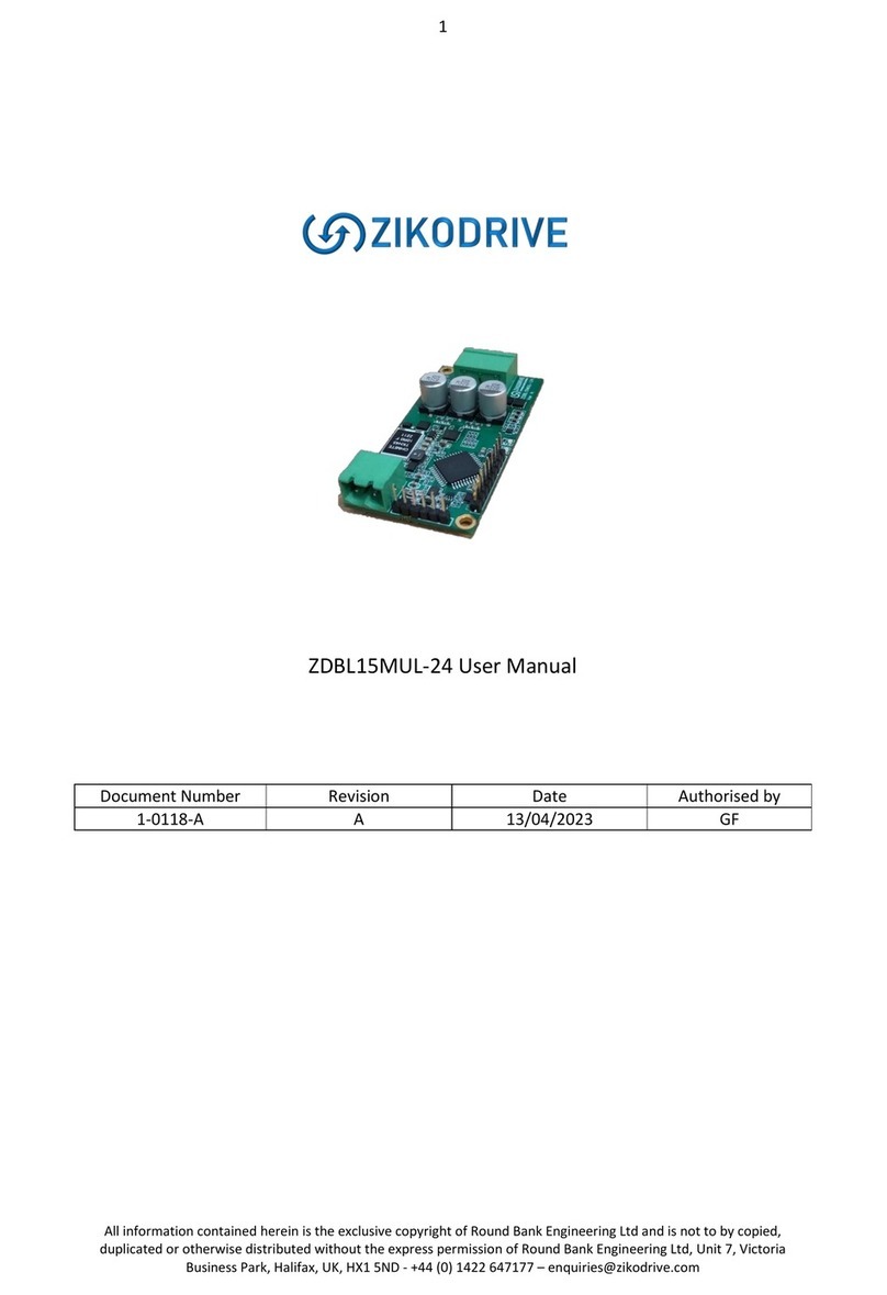
Zikodrive ZDBL30MUL-48 User manual

1
All information contained herein is the exclusive copyright of Round Bank Engineering Ltd and is not to by copied,
duplicated or otherwise distributed without the express permission of Round Bank Engineering Ltd, Unit 7, Victoria
ZDBL30MUL-48 User Manual
Document Number
Revision
Date
Authorised by
1-0116-A
A
03/02/2023
GF

2
All information contained herein is the exclusive copyright of Round Bank Engineering Ltd and is not to by copied,
duplicated or otherwise distributed without the express permission of Round Bank Engineering Ltd, Unit 7, Victoria
Contents
Overview.................................................................................................................................................4
Specifications ..........................................................................................................................................4
Connections ............................................................................................................................................5
Power Supply Connections .................................................................................................................5
Motor Connections.............................................................................................................................5
Analogue Input....................................................................................................................................6
Onboard Pot........................................................................................................................................6
UART Connections ..............................................................................................................................6
Programming Pin Connections............................................................................................................7
UART Control...........................................................................................................................................8
Using the UART ...................................................................................................................................8
Using ZDA010 software to set parameters.............................................................................................9
Getting Started / Setup.......................................................................................................................9
Port Setup .........................................................................................................................................10
Finding the right COM Port...............................................................................................................11
ZDA010 1.8 Overview........................................................................................................................12
Commands and Parameters..............................................................................................................13
General TAB ......................................................................................................................................14
Control Setup TAB.............................................................................................................................15
Drive Setup TAB ................................................................................................................................16
ZDA Commands.....................................................................................................................................17
COM Port Settings.............................................................................................................................17
Sending Commands ..........................................................................................................................17
Writing Commands ...........................................................................................................................17
General Commands ..........................................................................................................................18
Control Setup Commands.................................................................................................................19
Drive Setup Commands.....................................................................................................................20
Command & Parameter Details ............................................................................................................21
Control Setup Data Items..................................................................................................................21
Fault Codes & Fault Data ..................................................................................................................21
Invert Settings...................................................................................................................................21
Start Delay.........................................................................................................................................22
Analogue Scalers (Multiplier and Divider) ........................................................................................22

3
All information contained herein is the exclusive copyright of Round Bank Engineering Ltd and is not to by copied,
duplicated or otherwise distributed without the express permission of Round Bank Engineering Ltd, Unit 7, Victoria
Fixed Speed (%duty)..........................................................................................................................22
Duty Acc/Dec.....................................................................................................................................23
Fixed Speed (PID Hz) .........................................................................................................................23
PID Acc/Dec.......................................................................................................................................23
PID Delay (ms)...................................................................................................................................24
PID Enabled.......................................................................................................................................24
PID Data Items ..................................................................................................................................24
Output Setting...................................................................................................................................25
Bemf Data .........................................................................................................................................25
Data Export Time (ms) ......................................................................................................................25
Drive Data Items ...............................................................................................................................25
PWM Frequency................................................................................................................................26
Min Voltage.......................................................................................................................................26
Max Voltage......................................................................................................................................27
Start PWM.........................................................................................................................................27
Bemf Sum..........................................................................................................................................27
Using the controller ..............................................................................................................................28
Startup...............................................................................................................................................28
Fixed Speed Run................................................................................................................................30
POT Average Run...............................................................................................................................31
Analogue Average Run ......................................................................................................................32

4
All information contained herein is the exclusive copyright of Round Bank Engineering Ltd and is not to by copied,
duplicated or otherwise distributed without the express permission of Round Bank Engineering Ltd, Unit 7, Victoria
Overview
This manual covers the fundamentals of how to setup and use the ZDBL30MUL-48 sensorless
brushless DC motor controller. The manual covers setup and operation of the controller as well as
how to use the ZDA software to set any key parameters.
The controller uses Zikodrive’s ZikoOptimise technology to enable the controller to start motors
quickly and easily and then continuously optimise the drive to handle changes in load, temperature
and other factors.
For more information on this technology, please see our website at www.zikodrive.com
Specifications
Specification
Value
Units
Max Power
1400
W
Rated Power
700
W
Drive Method
High frequency Sensorless Trapezoidal
Min Voltage
8
V
Analogue Input
0-5
V
Operating Temperature Range
-20 to 85
Celsius
Max Voltage
55
V
Running Current
15
A
Max Current
30
A

5
All information contained herein is the exclusive copyright of Round Bank Engineering Ltd and is not to by copied,
duplicated or otherwise distributed without the express permission of Round Bank Engineering Ltd, Unit 7, Victoria
Connections
Power Supply Connections
The power supply connections are the clearly marked on the controller and indicated in the drawing
above. Power supply should be between 8-55VDC and you should set an appropriate current limit (if
using a PSU) to enable adequate power. Setting the current limit too low for your motor will result in
impaired performance and potentially will mean the controller will not start.
NOTE: the controller is protected against reverse polarity, however care should be taken to ensure
the polarity is correct before powering the controller.
DO NOT INCREASE THE VOLTAGE WHILE THE MOTOR IS RUNNING, THE BRAKE WILL BE ENABLED
AND WILL CAUSE THE BRAKE TO BECOME DAMAGED.
Motor Connections
Motor connections are on the opposite side of the controller to the power supply inputs. They are
clearly marked on the controller. Take care to match the motor phases with their appropriate
connection. Wiring the motor incorrectly may result in the motor not functioning or the motor
running in the opposite direction to that intended. The motor manufacturer should supply the wire
colour / motor phase information on the motor datasheet.

6
All information contained herein is the exclusive copyright of Round Bank Engineering Ltd and is not to by copied,
duplicated or otherwise distributed without the express permission of Round Bank Engineering Ltd, Unit 7, Victoria
Analogue Input
The analogue input is marked on the drawing above and is found on the pin header.
Connect the external analogue input between the “GND” and the “0-5V” connections
The analogue input runs through an RC low pass filter. This provided discrete filtering of the
analogue signal to ensure the signal is not affected by noise, as well as introducing a hardware slew
rate of the input signal.
NOTE: applying voltages over 5V to this input can permanently damage the controller. Take care
to ensure you have this correctly.
Onboard Pot
The onboard pot is marked on the drawing above and can be used to adjust speed if required.
NOTE: the onboard pot is a small trimmer pot and is not designed for constant adjustment. Care
must be taken when adjusting this that you do not over turn the pot as this can break the end
stops and lead to permanent damage.
UART Connections
The UART connections are highlighted on the wiring diagram above. These accept a max voltage of
3.3V on the RX or TX pins.
NOTE: applying voltages in excess of this will lead to permanent damage.
3V3 max voltage on either the RX or TX pins. The UART connections can be connected directly to
another microcontroller, or connected to a PC Serial Port using an FTDI cable “TTL-232R-3V3”. This
can be purchased on line at www.zikodrive.com.
NOTE: Ensure the RX and TX lines are crossed over to enable correct communication. Ie, TX from
PC goes to RX of the controller, and RX from PC goes to TX of the controller. Also, ensure a
common GND between the devices.
If another Microcontroller is used for communication, ensure the distance between the devices is
kept as short as possible and twisted pairs of the RX and TX lines are used. Contact us @
www.zikodrive.com for any additional information with regards to the UART ZDA protocol for the
ZDBL30MUL-48.

7
All information contained herein is the exclusive copyright of Round Bank Engineering Ltd and is not to by copied,
duplicated or otherwise distributed without the express permission of Round Bank Engineering Ltd, Unit 7, Victoria
Programming Pin Connections
These should not be needed in general use but if you have requested a custom program for a
specific application then these pins will need to be used. If this is the case we will supply separate
information on how to do this.

8
All information contained herein is the exclusive copyright of Round Bank Engineering Ltd and is not to by copied,
duplicated or otherwise distributed without the express permission of Round Bank Engineering Ltd, Unit 7, Victoria
UART Control
The UART connections are used to set up all the required user-settable parameters.
Please note that all parameters will be stored in EEPROM, this means that they are non-volatile and
the controller will remember these settings when the power is disconnected.
Zikodrive will provide an “ini” (Config) file that can be uploaded into ZDA software that can be used
to modify settings and parameters to suit the required application. These “ini” (Config) files can be
modified and saved for each of the application requirements using ZDA. The standard version of this
file is available for download from www.zikodrive.com.
Using the UART
The UART communication can be operated from any serial terminal program or microcontroller. If
you have a specific requirement for this or require any assistance please contact us directly and we
can advise on how best to achieve your requirements.
UART COM Port settings for the ZDBL30MUL-48:
Baud Rate: 115200, Data bits = 8, Parity = None, Stop bits = 0.

9
All information contained herein is the exclusive copyright of Round Bank Engineering Ltd and is not to by copied,
duplicated or otherwise distributed without the express permission of Round Bank Engineering Ltd, Unit 7, Victoria
Using ZDA010 software to set parameters
Getting Started / Setup
Open the .exe file from Zikodrive. Depending on your security settings you may be asked to verify
that the “.exe” file has come from a verified source. You will need to approve this with your security
system. Once open you should see a screen as below.
When first opened, the ZDA will be blank. You will need to open the initial “.ini” (Config) with the
settings of the required motor/pump/application created by Zikodrive. To do this, Click File > Load
Config and then locate the file location where the .ini file was saved (see below).

10
All information contained herein is the exclusive copyright of Round Bank Engineering Ltd and is not to by copied,
duplicated or otherwise distributed without the express permission of Round Bank Engineering Ltd, Unit 7, Victoria
Port Setup
On the main menu at the top of the page, select “COM” and then “Settings”.
You should then get the screen below. Ensure the settings are as below (with the exception of the
COM port which will vary depending on which port you have used on your device).
The first time the .ini (Config) file is loaded, it will attempt to open the COM Port number that was
previously saved in the .ini file. Please note that this may be incorrect when first using the software.
It is nonetheless a simple change to make. Simply close the COM port by selecting “COM” and
“Close”. Then open the “Settings” option, change the COM port to the correct one and then select
“COM” and “Open”.
NOTE: every time you wish to change COM port, you must ensure you close the COM port, change
it, then Open the correct one.

11
All information contained herein is the exclusive copyright of Round Bank Engineering Ltd and is not to by copied,
duplicated or otherwise distributed without the express permission of Round Bank Engineering Ltd, Unit 7, Victoria
Finding the right COM Port
COM Port- This will change depending on which port the FTDI cable has been connected to. If you
are not sure and need to check this, use the following steps;
1. Plug the FTDI cable into the PC.
2. Open Device Manager in Windows and look for Ports (COM & LPT).
3. Unplug the FTDI cable and note which COM port is then removed from the device list.
4. This is the COM port you then need to select.

12
All information contained herein is the exclusive copyright of Round Bank Engineering Ltd and is not to by copied, duplicated or otherwise distributed without the express permission of
Round Bank Engineering Ltd, Unit 7, Victoria Business Park, Halifax, UK, HX1 5ND - +44 (0) 1422 647177 –[email protected]
ZDA010 1.8 Overview

13
All information contained herein is the exclusive copyright of Round Bank Engineering Ltd and is not to by copied,
duplicated or otherwise distributed without the express permission of Round Bank Engineering Ltd, Unit 7, Victoria
Commands and Parameters
Commands (Itemised in Blue colouring in ZDA) are used to retrieve data from the controller. For
example, querying the motor speed or the fault code/fault data. Commands do not change any
parameters or variables within the controller.
Commands are split up into two categories. Basic Commands that have no associated values (No
values can be typed into the text box) and when the “Tx” button is pressed, there can only be one
response (displayed in the Text Window near the bottom of the software). There are also advanced
commands that allow values to be typed into the associated text box. Each value typed into the text
box will command different data within the controller. More details on the advanced commands and
their associated values can be found in the “Commands & Parameters” section of this document.
Commands only have a “Tx” button. Basic commands will return their values as soon as this button is
pressed, where as advanced commands will return values depending on the number in the adjacent
text box when the “Tx” button is pressed.
Parameters are the user programmable variables that can be changed to suit the required motor or
application. All parameters are stored in non-volatile memory and can be either read, or written to.
There are limits set both via the ZDA software, as well as within the controller firmware to ensure
new parameters cannot be set out of bounds.
Parameters have two associated buttons. The “G” button represents “Get Parameter Value” where
as the “S” represents “Set Parameter Value”.

14
All information contained herein is the exclusive copyright of Round Bank Engineering Ltd and is not to by copied,
duplicated or otherwise distributed without the express permission of Round Bank Engineering Ltd, Unit 7, Victoria
General TAB
This tab is used to read some general information within the controller. To receive data click the “Tx”
button.
Application Name
Provided information on
the Hardware and
version.
Application Version
Provides information on
the Firmware. 101
indicates Version 1.01.
Application Build
Number
Increments every time
the firmware is built. 100
indicates V1.00.
Reset
Resets the
microcontroller when
pressed.
Supply Voltage (Vx10)
Reads the Voltage of the supply
x 10. So a value of 125 gives
12.5V.
Motor I (Ax10)
Reads the Motor Current x 10.
So a value of 42 gives 4.2A.
Controller Temp (degC)
Reads the controller
Temperature in degrees C. So a
value of 38 gives 38degC.
Analogue Value
Reads the Raw analogue value
of the Analogue input. Range
between 0-4095.
Pot Value
Reads the Raw Potentiometer
value of the onboard Pot Range
between 0-4095.
Enable Input Value
Reads the Enable input (Note –May be inverted from physical
input depending on “Invert Settings” Value
Direction Input Value
Reads Direction input (Note –May be inverted from physical input
depending on “Invert Settings” Value
Motor Power (W)
Reads the power to the motor.

15
All information contained herein is the exclusive copyright of Round Bank Engineering Ltd and is not to by copied,
duplicated or otherwise distributed without the express permission of Round Bank Engineering Ltd, Unit 7, Victoria
Control Setup TAB
These are the parameters used to set up various applications.
For Parameters (variables that are stored in non-volatile EEPROM Memory) each Box has a “G” and
an “S” button. The “G” button is for GET parameter from the controller (this will read the value
stored on the controller and display this in the adjacent box). The “S” is the SET parameter in the
controller (this will set the parameter that is in the adjacent box to the controller).
More information regarding each parameter can be found in the “Command & Parameter Details”
section of this document.
Data Item
Reads various variables
within the Drive Module.
Fault Code
Reads the Drive Fault
Code if something has
gone wrong.
Fault Data
Reads the data of the
fault.
Reset Fault
Resets the fault code.
Invert Settings
Changes Polarity of the Inputs
Start Delay
Delays the time between
powering up and motor
starting (if Enable input is true)
Analogue Scaler
Scales the Analogue input and
the Pot input.
Fixed Speed (% Duty)
Sets the PWM duty cycle
when no PID is used.
Duty Acc/Dec
Acceleration and Deceleration rates when no PID is used.
Fixed Speed (PID Hz)
Sets the Target Frequency
when the PID is used.
PID Acc/Dec
Acceleration and Deceleration rates when the PID is used.
PID Delay (ms)
Sets the delay between motor
starting and PID switching on.
PID Enable
1 = PID is switched ON, 0 PID is
switched OFF.
Motor Speed (Hz)
Reads the motor speed
Data Export Time (ms)
Sets the timing between data points when exporting. 0 = No
export Data.
PID Data Item
Returns variables within the
PID Module.
Output Setting
Changes function of the
output pin

16
All information contained herein is the exclusive copyright of Round Bank Engineering Ltd and is not to by copied,
duplicated or otherwise distributed without the express permission of Round Bank Engineering Ltd, Unit 7, Victoria
Drive Setup TAB
These are the parameters used for setting up the motor drive.
Data Item
Reads various variables
within the Drive Protect
Module. See below.
Fault Code
Reads the Drive Protect
Fault Code if something
has gone wrong.
Fault Data
Reads the data of the
fault.
Reset Fault
Resets the fault code.
Min Voltage (Vx10)
Minimum supply voltage x 10
before the controller stops
motor and generates fault
code. Ie, 90 = 9.0V.
Max Voltage (Vx10)
Maximum supply voltage x 10
before the controller stops
motor and generates fault
code. Ie, 165 = 16.5V.
Start PWM
PWM Duty Cycle used to Start
the motor.
Min Duty Cycle (%)
Deceleration End Duty Cycle.
PWM Frequency (Khz)
Sets the PWM Frequency to
the motor.
Max Trip Current (Ax10)
Trip Current Setting.
Min Frequency (Hz)
Deceleration End Frequency on
PID.
Max Trip Power
Trip Power Setting.
Back EMF Sum
This is the Self calibration value
Save BEMF Sum
Click this button to save the current BEMF value to
be used on Power up.
Enable Self Calibration
Used to either enable or disable the self-calibration
algorithms.

17
All information contained herein is the exclusive copyright of Round Bank Engineering Ltd and is not to by copied,
duplicated or otherwise distributed without the express permission of Round Bank Engineering Ltd, Unit 7, Victoria
ZDA Commands
For more information on each of the commands check the

18
All information contained herein is the exclusive copyright of Round Bank Engineering Ltd and is not to by copied,
duplicated or otherwise distributed without the express permission of Round Bank Engineering Ltd, Unit 7, Victoria
Command & Parameter Details section.
COM Port Settings
UART COM Port settings for the ZDBL30MUL-48:
Baud Rate: 115200, Data bits = 8, Parity = None, Stop bits = 0.
Sending Commands
To Send commands to get data, you must send a string of data followed by a \r.
e.g. to get the application name, the string sent must be ZSVERSTR\r. This will then return a string of
ZDVERSTR = ZDBL30MUL-48\r
The data after the equal sign is the data reply. So in this instance, the result is ZDBL30MUL-48.
Writing Commands
Writing Commands is like reading, with the main difference being that there is an added part to the
string where you state what the new value should be.
e.g. to set X send the command ZDInvSet = 1\r. If the string is acknowledged by the controller, the
host will receive the string ZDInvSet = 1\r.
If the value sent is limited by the controller, the command returned will be set to the closest
maximum or minimum limit value.
If the String is sent without the “= x” part of the string, the controller will send you the value that is
set.

19
All information contained herein is the exclusive copyright of Round Bank Engineering Ltd and is not to by copied,
duplicated or otherwise distributed without the express permission of Round Bank Engineering Ltd, Unit 7, Victoria
General Commands
Command Description
Command String
Result meaning
Read/Write?
Application Name
ZDVERSTR\r
ZDVERSTR = ZDBL30MUL-48\r
Version = ZDBL30MUL-48
Read Only
Application Version
ZDVER\r
ZDVER = 100\r
Version 1.00
Read Only
Application Build
Number
ZDVERBN\r
ZDVERBN = 1000\r
Build number = 1000
Read Only
Reset
ZDreset\r
N/A, no reply
Write Only,
no reply
Supply Voltage (Vx10)
ZDvsup\r
ZDvsup = 200\r
Supply Voltage = 20V
Read Only
Motor I (Ax10)
ZDimot\r
ZDimot = 3\r
Motor Current = 0.3A
Read only
Motor Power (W)
ZDpmot\r
ZDpmot = 3\r
Motor Power = 3W
Read only
Controller Temp.
(degC)
ZDctemp\r
ZDctemp = 24\r
Controller Temp = 24 degC
Read Only
Analogue Value
ZDanip\r
ZDanip = 150\r
Analogue Value = 150
Read Only
Pot Value
ZDpotv\r
ZDpotv = 150\r
Pot Value = 150
Read only
Enable Input Value
ZDdinp1\r
ZDdinp1 = 1\r
Enable Input Value = 1
Read Only
Enable Dir Value
ZDdinp2\r
ZDdinp2 = 1\r
Enable Dir Value = 1
Read Only

20
All information contained herein is the exclusive copyright of Round Bank Engineering Ltd and is not to by copied,
duplicated or otherwise distributed without the express permission of Round Bank Engineering Ltd, Unit 7, Victoria
Control Setup Commands
Command Description
Command String
Result meaning
Read/Write?
Data Item
ZDdcdati = x\r
ZDdcdati = 0\r
ZDdcdati = 9, dcDatai 0 = State,
drive control data item state = 9.
Check Control Setup Data Items for
more info on data items.
Read only
Fault Code
ZDdcfltc\r
ZDdcfltc = 3\r
Fault code = 3 = Min Voltage.
For specific fault codes check Fault
Codes & Fault Data
Read Only
Fault Data
ZDdcfltd\r
ZDdcfltd = 251\r
Fault data = 25.1V
For specific fault data check Fault
Codes & Fault Data
Read Only
Reset
ZDdcrflt\r
ZDdcrflt\r, fault reset
Write Only
Invert Settings
ZDInvSet\r
ZDInvSet = 0\r
Invert Setting = 0. For more
information check Invert Settings.
Read/ Write
Start Delay
ZDSrtDly\r
ZDSrtDly = 5000\r
Start delay = 5 seconds.
Read/ Write
Motor Speed (Hz)
ZDdcdati = 9\r
ZDdcdati = 120\r
120 = 120Hz.
Read Only
Analogue Scaler Mult
ZDAnlSclm\r
ZDAnlSclm = 2\r
Analogue Scalar multiplier = 2.
Read/ Write
Analogue Scaler Div
ZDAnlScld\r
ZDAnlScld = 2\r
Analogue Scalar divider = 2.
Read/ Write
Bemf Data
ZDDatEmf\r
ZDDatEmf = 2500\r
Bemf Data = 2500.
Read Only
Fixed Speed (%Duty)
ZDFixSpd\r
ZDFixDps = 500\r
Fixed speed (%Duty) = 500 = 50%
Read/ Write
Duty Acc/Dec
ZDDCADRT\r
ZDDCADRT = 10\r
Duty Acc/Dec = 10.
Read/ Write
DataExport Time (ms)
ZDDatExp\r
ZSDatExp = 0\r
DataExport Time = 0ms.
Read Only.
Fixed Speed (PID Hz)
ZDFSpdPd\r
ZDFSpdPd = 100\r
Fixed Speed (PID Hz) = 100.
Read/ Write
PID Acc/Dec
ZDDCADPd\r
ZDDCADPd = 5\r
PID Acc/Dec rate = 5.
Read/ Write
PID Delay (ms)
ZDPIDDly\r
ZDPIDDly = 200\r
PID Delay = 200mS.
Read/ Write
PID Enabled
ZDPIDEn\r
ZDPIDEn = 1\r
PID = 1 = enabled
Read/ Write
Output Setting
ZDOP1\r
ZDOP1 = 1\r
Output mode = 1, high on fault
Read/ Write
PID Data Item
ZDpiddat = x\r
ZDpiddat = 0
Check PID Data Items for more
information.
Read
Table of contents
Other Zikodrive Computer Hardware manuals
Popular Computer Hardware manuals by other brands

Omron
Omron G3NE manual

WIN Enterprises
WIN Enterprises MB-60480 user manual

Command access
Command access DS1+ installation instructions

head rush technologies
head rush technologies PRIME quick start guide

Analog Devices
Analog Devices ADSP-CM411F manual

Freescale Semiconductor
Freescale Semiconductor MCF5329 Reference manual