JYTEK PCIe-6301 Series User manual

PCIe/PXIe-6301 Series
24 bits Temperature Input
Module for Resistance
Temperature Detector User
Manual
User Manual Version: V2.1.3
Revision Date: Aug 19, 2021

Table of Contents
1.Overview ........................................................................................................... 1
Introduction .....................................................................................................1
Main Features ..................................................................................................2
Abbreviations...................................................................................................2
1.4 Learn by Example.............................................................................................2
2.Hardware........................................................................................................... 4
Sensor Connection...........................................................................................4
Analog Hardware Specifications ......................................................................8
Resistance Measurement Accuracy.................................................................9
Resistance Measurement Noise ....................................................................10
Temperature Measurement Accuracy...........................................................11
PFI...................................................................................................................11
Trigger ............................................................................................................11
Clock...............................................................................................................12
Physical and Environment..............................................................................12
Front Panel conections and Pinouts ............................................................13
3.Software...........................................................................................................17
System Requirements ....................................................................................17
System Software ............................................................................................17
C# Programming Language ............................................................................18
PCIe/PXIe-6301 Hardware Driver...................................................................18
Install the SeeSharpTools from JYTEK............................................................18
Running C# Programs in Linux .......................................................................18
4.Operating PCIe/PXIe-6301 Modules ..................................................................20
Quick Start......................................................................................................20
AI Operations .................................................................................................20
4.2.1 Channel Scan Sequence ......................................................................22
4.2.2 ADC Timing Modes..............................................................................25
4.2.3 Sampling Rate .....................................................................................25
Conversion of Resistance and Temperature..................................................28
Trigger Source ................................................................................................29
4.4.1 Immediate Trigger...............................................................................29
4.4.2 Software Trigger..................................................................................30
4.4.3 External digital trigger.........................................................................30
Trigger Mode..................................................................................................33
4.5.1 Start Trigger ........................................................................................33
4.5.2 Reference Trigger................................................................................35

4.5.3 Retrigger..............................................................................................35
Learn by Example 4.5.2 and 4.5.3................................................................36
System Synchronization Interface(SSI)for PCIe Modules.........................38
DIP Switch in PCIe-6301.................................................................................39
5.Calibration........................................................................................................40
6.Using PCIe/PXIe-6301 in Other Software ...........................................................41
Python............................................................................................................41
C++ .................................................................................................................41
7.Appendix ..........................................................................................................42
System Diagram .............................................................................................42
PT100 Temperature/Reisitance Table ...........................................................42
Typical Resistance Measurement Noises.......................................................45
Gain and Offset Stability Tests.......................................................................50
Reistance Measurement Error.......................................................................51
Gain and Offset Error Stability .......................................................................55
8.About JYTEK......................................................................................................55
JYTEK China ....................................................................................................55
JYTEK Korea and JYTEK in Other Countries....................................................55
JYTEK Hardware Products ..............................................................................55
JYTEK Software Platform................................................................................56
JYTEK Warranty and SupportServices............................................................56
9.Statement.........................................................................................................57
Figure 1 JYPEDIA Information ................................................................................3
Figure 2 TB- 68 terminal block ...............................................................................3
Figure 3 2-wire RTD connection.............................................................................4
Figure 4 3-wire RTD connection.............................................................................6
Figure 5 4-wire RTD connection.............................................................................7
Figure 6 PXIe/PCIe 6301 Front Panel ...................................................................13
Figure 7 AI Continuous Paraments ......................................................................21
Figure 8 Single Channel Continuous Acquisition .................................................21
Figure 9 Typical channel scan sequence..............................................................22
Figure 10 Random channel scan sequence..........................................................23
Figure 11 AI MutilChannel Continuouas Paraments............................................24
Figure 12 MultiChannel Continuous Acquisition .................................................24
Figure 13 A / D conversion and sampling ............................................................26
Figure 14 Immediate Trigger Paraments .............................................................29

Figure 15 Rising and falling edges of digital signals.............................................30
Figure 16 Digital Trigger Paraments.....................................................................31
Figure 17 Digial Trigger Acquisition .....................................................................32
Figure 18 Start Trigger Mode...............................................................................33
Figure 19 Start Trigger Paraments.......................................................................34
Figure 20 Reference Trigger mode ......................................................................35
Figure 21 Retrigger mode ....................................................................................36
Figure 22 Retrigger Paraments ............................................................................36
Figure 23 Retrigger in Reference Trigger Mode ..................................................37
Figure 24 Retrigger Complete State.....................................................................37
Figure 25 SSI Connector in PCIe-6301..................................................................38
Figure 26 DIP Switch in PCIe-6301.......................................................................39
Figure 27 PCIe/PXIe-6301 System Diagram .........................................................42
Figure 28 Resistance Measurement noise (4-wire, Level 0)................................45
Figure 29 Resistance Measurement noise (4-wire, Level 1)................................45
Figure 30 Resistance Measurement noise (4-wire, Level 2)................................46
Figure 31 Resistance Measurement noise (4-wire, Level 3)................................46
Figure 32 Resistance Measurement noise (4-wire, Level 4)................................47
Figure 33 Resistance Measurement noise (4-wire, Level 5)................................47
Figure 34 Resistance Measurement noise (3-wire, Level 0)................................48
Figure 35 Resistance Measurement noise (3-wire, Level 1)................................48
Figure 36 Resistance Measurement noise (3-wire, Level 2)................................49
Figure 37 Resistance Measurement noise (3-wire, Level 3)................................49
Figure 38 Resistance Measurement noise (3-wire, Level 4)................................50
Figure 39 Resistance Measurement noise (3-wire, Level 5)................................50
Figure 40 Typical Drift (250 Ω Input) ...................................................................51
Figure 41 Typical Drift (Different Inputs).............................................................51
Figure 42 Typical Error (4-wire,100Ω Input)........................................................52
Figure 43 Typical Error (4-wire,250Ω Input)........................................................52
Figure 44 Typical Error (3-wire,100Ω Input)........................................................53
Figure 45 Typical Error (3-wire,250Ω Input)........................................................53
Figure 46 Typical Error (2-wire,100Ω Input)........................................................54
Figure 47 Typical Error (2-wire,250Ω Input)........................................................54
Table 1 PCIe/PXIe-6301 Channel Group ................................................................1
Table 2 6301 on different buses ............................................................................4
Table 3 Analog Input Performance ........................................................................8

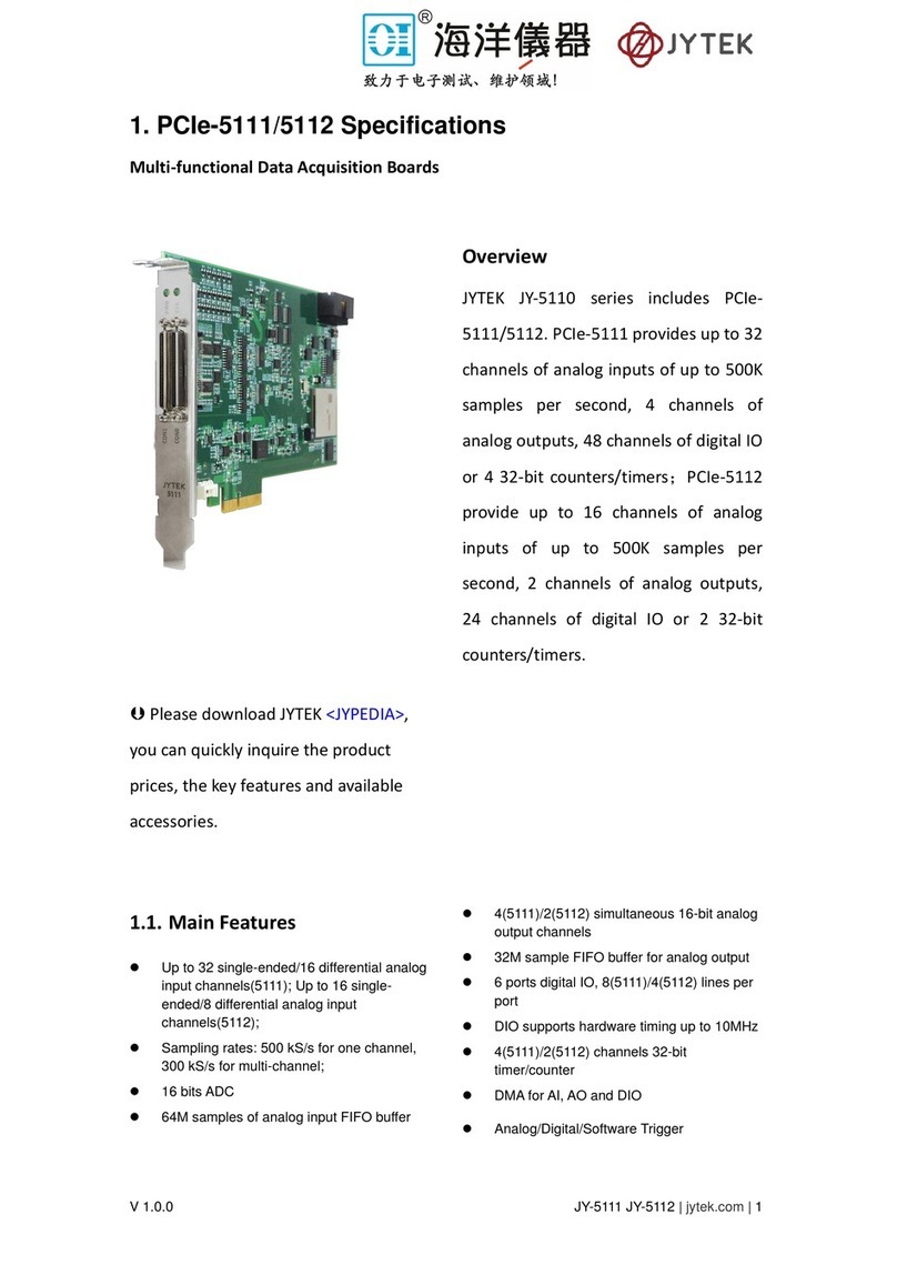
Table 4 Resistance Measurement Accuracy ..........................................................9
Table 5 Resistance Measurement noise ..............................................................10
Table 6 6301 Temperature Measurement Accuracy ...........................................11
Table 7 PFI Specification ......................................................................................11
Table 8 Trigger Specification................................................................................12
Table 9 Clock Specification...................................................................................12
Table 10 Physical and Environment.....................................................................12
Table 11 Pinouts for “4-wire mode” configuration (supports 2-wire, 3-wire or 4-
wire RTD)......................................................................................................14
Table 12 Pinouts for “3-wire mode “configuration (supports 2-wire, 3-wire RTD)
......................................................................................................................15
Table 13 Different RTD wiring methods ..............................................................16
Table 14 Supported Linux Versions .....................................................................17
Table 15 A/D conversion time at different speed levels .....................................25
Table 16 ADC Timing Modes and maximum aggregate sampling rate................26
Table 17 SSI Connector Pin Assignment for PCIe-6301 .......................................38
Table 18 Relationship between switch position and card number .....................39
Table 19 Resistance Measurement Stability........................................................55

PCIe/PXIe-6301 Series | jytek.com | 1
1. Overview
This chapter presents the information how to use this manual and operate the module
if you are already familiar with Microsoft Visual Studio and C# programming language.
Introduction
JYTEK PCIe/PXIe-6301 is a high-resolution and high-speed temperature measurement
module designed for PT100 Resistance Temperature Detector (RTD).
PCIe/PXIe-6301 supports two wiring topologies, “4-wire mode” and “3-wire mode”,
which can be selected by software.
“4-wire mode”: each channel can support 2-wire, 3-wire or 4-wire RTD configuration
and the module provides 20 channels of analog temperature measurements.
“3-wire mode”: each channel can support 2-wire or 3-wire RTD configuration and the
module provides 32 channels of analog temperature measurements.
PCIe/PXIe-6301 can measure resistance up to 400 Ωto cover the full range of PT100
RTD measurements and the maximum sampling rate is up to 800 samples per second.
The PCIe/PXIe-6301 supports digital and software trigger. All trigger signals are routed
through PFI or PXI chassis backplane.
PCIe/PXIe-6301 module channel grouping is shown in Table 1.
Table 1 PCIe/PXIe-6301 Channel Group
Wiring topology ADC Channels
ADC 0 Ch0, Ch1, Ch2, Ch3, Ch4
ADC 1 Ch5, Ch6, Ch7, Ch8, Ch9
ADC 2 Ch10, Ch11, Ch12, Ch13, Ch14
ADC 3 Ch15, Ch16, Ch17, Ch18, Ch19
ADC 0 Ch0, Ch1, Ch2, Ch3, Ch4, Ch5, Ch6, Ch7
ADC 1 Ch8, Ch9, Ch10, Ch11, Ch12, Ch13, Ch14, Ch15
ADC 2 Ch16, Ch17, Ch18, Ch19, Ch20, Ch21, Ch22, Ch23
ADC 3 Ch24, Ch25, Ch26, Ch27, Ch28, Ch29, Ch30, Ch31
4-wire mode
3-wire mode

PCIe/PXIe-6301 Series | jytek.com | 2
Main Features
⚫32 channels (3-wire mode), 20 channels (4-wire mode)
⚫24 bits ADC resolution
⚫-200 °C ~ +850 °C measurement range (using PT100)
⚫0 ~ 400 Ω range
⚫The balance line resistance compensation is provided under the 3-wire RTD
measurements
⚫128M sample onboard FIFO buffer for analog input
⚫DMA for analog input
⚫Provide resistance or temperature measurement value
⚫Digital/Software Trigger
Abbreviations
AI: Analog Input
ADC: Analog to Digital Converter
PFI: Programmable Function Interface
RTD: Resistance Temperature Detector
Ex+: Positive terminal of current Excitation
Ex-: Ngative terminal of current Excitation
RDC: Resistance-to-Digital Converter
OS: Operating System
1.4 Learn by Example
JYTEK has added Learn by Example in this manual. We provide many sample programs
for this device. You can download a JYPEDIA excel file from our web www.jytek.com.
Open JYPEDIA and search for JY6301 in the driver sheet, select JY6301_Examples.zip.
This will lead you to download the sample program for this device. In addition to the
download information, JYPEDIA also has a lot of other valuable information, JYTEK
highly recommend you use this file to obtain information from JYTEK.

PCIe/PXIe-6301 Series | jytek.com | 3
Figure 1 JYPEDIA Information
In a Learn by Example section, the sample program is in bold style such as Winform
AI Continuous MultiChannel; the property name in the sample program is also in bold
style such as SamplesToAcquire; the technical names used in the manual is in italic
style such as SampleRate. You can easily relate the property names in the example
program with the manual documentation.
In a Learn by Example section, the experiment is set up as follow. A PCIe/PXIe-6301
card is plugged in a desktop computer. The PCIe/PXIe-6301 is connected to a TB- 68
terminal block. A signal source is also connected to the same terminal block as shown
in Figure 2.
Figure 2 TB- 68 terminal block
Drivers Update Date
JY6301_V3.0.0_Linux.tar 2021/2/5
JY6301_V3.0.0_Win.zip 2021/2/5
JY6301_V3.0.0_Examples.zip 2021/2/5
Drivers are often updated, please register and receive the update information.

PCIe/PXIe-6301 Series | jytek.com | 4
2. Hardware
The JYTEK 6301 series are one of the family of temperature measurement module,
which can run on PCIe, PXIe, TXI (Thuderbolt) and USB buses (coming soon). JYTEK
6301 series on different buses are shown in Table 2.
Table 2 6301 on different buses
Sensor Connection
PCIe/PXIe-6301 can support 2-wire, 3-wire or 4-wire RTD connection at the same time.
The wiring configuration used by each channel can be independently configured by
software.
2-wire RTD connection
When using a 2-wire RTD configuration, user needs to connect the negative terminal
of current excitation (Ex-) to the AI- terminal as shown in Figure 3. Due to the presence
of lead wires resistance, this type of connection may introduce large measurement
errors, which are related to the material of the lead wire. This type of wiring is not
suitable for high precision temperature measurement needs.
Figure 3 2-wire RTD connection
6301 Model PCIe PXIe TXI USB
6301
√ √ √ √

PCIe/PXIe-6301 Series | jytek.com | 6
3-wire RTD connection
In a 3-wire RTD configuration, AI+ terminal will output a precision current excitation,
500 µA to RTD sensor and flow back through the Ex- terminal and AI- terminal as
shown in Figure 4 . Since the voltage generated by the RTD connecting the AI+ terminal
and the voltage connected to the AI- terminal will cancel each other, this connection
can effectively eliminate the influence of the lead wire resistance, but in practical
applications, the resistance of the two lead wires is difficult to match completely, so
there will still be a certain degree of mismatch error.
Figure 4 3-wire RTD connection

PCIe/PXIe-6301 Series | jytek.com | 7
4-wire RTD connection
1
In a 4-wire configuration, the Ex+ terminal will output a current excitation, 1000 µA
and flows back through the Ex- terminal and AI- terminal as shown in Figure 5. Since
the current loop and voltage measuring circuit of the lead wire are independently, so
will not introduce errors due to lead wire resistance.
Figure 5 4-wire RTD connection
1
If you need to use a 4-wire configuration, you must configure the channel topology to a “4-wire mode” when
configuring the acquisition task. In this case, the PCIe/PXIe-6301 provides a 20 channels of temperature
measurements. If you do not need to use a 4-wire configuration, you can configure the acquisition task to a “3-
wire mode”, in which case the PCIe/PXIe-6301 provides a 32 channels of temperature measurements.

PCIe/PXIe-6301 Series | jytek.com | 8
Analog Hardware Specifications
Table 3 Analog Input Performance
PCIe/PXIe-6301’s 32 channels are grouped by 4 banks, each having 8 channels. The
sampling rate per channel must be divided by the sampling rate per bank.
The sample rate parameters are used by PCIe/PXIe-6301 driver software to select the
internal ADC Timing Mode which ultimate determines how fast the measurement
values are being returned.
32ch (2-wire/3-wire)
20ch (2-wire/3-wire/4-wire)
Synchronous acquisition No
Sensor support RTD PT100
ADC resolution 24 bits
ADC type Δ-Σ
Input isolation Yes
800 Sample/s/N (N=1-8)
160 Sample/s ( 2-wire/3-wire/4-wire, 20ch fully used)
100 Sample/s ( 2-wire/3-wire, 32ch fully used)
Clock
Onboard (25 MHz)
PX I_CLK100
Clock in (PCIe /TX I Only)
Storage depth 128M Samples
Measuring range 0 Ω ~ 400 Ω / -200 ℃~ +850 ℃(for PT100)
Terminal type 2-wire/3-wire/4-wire
1000 µA (4-wire)
500 µA (2-wire/3-wire)
Overvoltage protection ±30 V
Trigger type Digital/Software
Analog trigger range 0 Ω ~ 400 Ω / -200 ℃~ +850 ℃(for PT100)
Trigger mode StartTrigger,ReferenceTrigger,ReTrigger
Digital trigger sourse
PX I_TRIG <0..7>
PX I_STAR
PFI<0..7>
Number of channels
Sampling Rate Per Bank (4
Banks, 8 Chs/Bank), 4 Banks
Use Same Sample Rate
Excitation current
ADC Timing Modes single conversion rate Single A/D conversion time
Level 0 2.3 Hz 434.7826 ms
Level 1 5.1 H z 196 .0784 ms
Level 2 26.5 Hz 37.7358 ms
Level 3 41 Hz 24.3902 ms
Level 4 410 Hz 2.4390 ms
Level 5 830 Hz 1.1205 ms

PCIe/PXIe-6301 Series | jytek.com | 9
Internally, the ADC operates at the single conversion rate per each bank. For multiple
channels in the same bank, the sample rates are further reduced. For example, if you
chose 800S/s sample rate, the driver software will automatically select level 5 for you.
Your measurement accuracy will be determined by Level 5. For accuracies at different
levels, please refer to Table 6.
Resistance Measurement Accuracy
PCIe/PXIe-6301 measures RTD resistance. It has built-in filters to improve the
measurement accuracy.
The accuracy is defined by:
Accuracy = Gain Error (% of reading) + Offset Error (mΩ).
The single point resistance measurement accuracy is shown in Table 4. The offset error
has included 6 times of noise error for that level. The ADC level is chosen by the driver
software, it corresponds to internal ADC conversion rate. This information is important
for you if you want to further improve the accuracy by averaging the acquired
resistance values. At level 0, ADC already works at 2.3Hz, most system noise is being
removed already. Please refer to 2.4.
Table 4 Resistance Measurement Accuracy
JY6301 Accuracy = ±(Gain Error % + Offset Error mΩ)
Temperature ADC Level
Internal
ADC Rate
(Hz)
Full Scale
Accuracy
@ 100Ω
(2,3-wires)
Full Scale
Accuracy @
100Ω(4-
wires)
Tcal±5 ℃Level 0 2.3 0.0462 + 25.9 0.0462 + 25.3 30.5 mΩ 30.0 mΩ
Tcal±5 ℃Level 1 5.1 0.0462 + 26.2 0.0462 + 25.5 30.8 mΩ 30.1 mΩ
Tcal±5 ℃Level 2 26.5 0.0462 + 26.8 0.0462 + 26.3 31.4 mΩ 30.9 mΩ
Tcal±5 ℃Level 3 41.0 0.0462 + 26.8 0.0462 + 26.6 31.5 mΩ 31.2 mΩ
Tcal±5 ℃Level 4 410.0 0.0462 + 31.1 0.0462 + 30.2 35.7 mΩ 34.8 mΩ
Tcal±5 ℃Level 5 830.0 0.0462 + 56.3 0.0462 + 44.6 60.9 mΩ 49.2 mΩ
Tcal=25℃typical.
Add 0.0160% to the gain, 20mΩ to the offset for temperatures outside Tcal±5 ℃
Offset error contains 3σ,σ is the noise error.
2, 3-wires
4-wires

PCIe/PXIe-6301 Series | jytek.com | 10
Resistance Measurement Noise
Table 5 shows the resistance measurement noises at different ADC levels. 6 times of
the noise level are added to the offset error in Section 2.3. You typically do not use
this information directly.
Table 5 Resistance Measurement noise
Timing
mode
single
conversion
rate
Single A/D
conversion
time
Noise(2-wire/3-
wire)(RMS)
Noise(4-wire)
(RMS)
Level 0 2.3 Hz 434.7826 ms 0.35 mΩ0.18 mΩ
Level 1 5.1 H z 196 .0784 ms 0.45 mΩ0.24 mΩ
Level 2 26.5 Hz 37.7358 ms 0.65 mΩ 0.5 mΩ
Level 3 41 Hz 24.3902 ms 0.68 mΩ0.6 mΩ
Level 4 410 Hz 2.4390 ms 2.1 mΩ1.8 mΩ
Level 5 830 Hz 1.1205 ms 10.5 mΩ6.6 mΩ

PCIe/PXIe-6301 Series | jytek.com | 11
Temperature Measurement Accuracy
The temperature measurement is converted from the resistance measurement. The
Table 6 lists the temperature measurement accuracies for different wire
configurations.
Table 6 6301 Temperature Measurement Accuracy
The typical temperature noises from each wire configuration are listed at Appendix
7.5.
PFI
The PFIs(Programable Fuction Interface) are digital IO interfaces and are used for
general purpose IO, a trigger input/ output, a clock-in and clock out. In 6501, the PFI
can only be used for the external digital triggering and cannot be configured as output.
Table 7 PFI Specification
Trigger
Temperature Accuracy
Levels
Maximum Total
Sample Rate(S/s)
(-200ºC,2,3-
wires)(ºC)
(-200ºC,4-
wires) (ºC)
(850ºC,2,3-
wires) (ºC)
(850ºC,4-
wires) (ºC)
Level 0 2.2 0.06 0.06 0.12 0.12
Level 1 5 0.07 0.06 0.12 0.12
Level 2 25 0.07 0.07 0.13 0.13
Level 3 40 0.07 0.07 0.13 0.13
Level 4 400 0.09 0.08 0.16 0.15
Level 5 800 0.21 0.15 0.33 0.25
Wiring resistance negligible
Operating temperature =25
Number of channels 8 (4 of them have hardware pull-ups)
Trigger voltage:5 V TTL
Trigger edge:Rising /Falling
Initial state Input*
External digital trigger interface
*6301's PFI is only used for external digital triggering, cannot be configured as output
Digital trigger
Trigger source:PX I_TRIG <0..7>, PX I_STAR, PFI <0..7>
Trigger mode:Start Trigger, Reference Trigger
Trigger polarity:Software-selectable

PCIe/PXIe-6301 Series | jytek.com | 12
Table 8 Trigger Specification
Clock
Table 9 Clock Specification
Physical and Environment
Table 10 Physical and Environment
Analog trigger
Trigger source:AI CH<0..31>
Trigger mode:Start Trigger, Reference Trigger
Trigger polarity:Software-selectable
Clock source:On Board
Clock Destination:Sample Clock
Bus
PXIe standard:x4 PXI Express module, specification rev 1.0 compliant
Slot supported:x1 and x4 PXI Express or PXI Express hybrid slots
Size
External physical size:3U PXIE
Weight:190 g
Operating Environment
Ambient temperature range 0 °C to 50 °C
Relative humidity range 20% to 80%, noncondensing
Storage Environment
Ambient temperature range -20℃to 80℃
Relative humidity range 10% to 90%, noncondensing
Power
3.3 V: 2.0 A
12 V: 0.04 A

PCIe/PXIe-6301 Series | jytek.com | 14
Table 11 Pinouts for “4-wire mode” configuration (supports 2-wire, 3-wire or 4-wire RTD)
Channel Pin No. Description Channel Pin No. Description
P43
Ex+, Positive terminal of current excitation (only for
4-wire mode)
P43
Ex+, Positive terminal of current excitation (only for
4-wire mode)
P35 AI+, resistance measurement high side P35 AI+, resistance measurement high side
P1 AI- , resistance measurement low side P1 AI- , resistance measurement low side
P36 Ex- , Negative terminal of current exciation P36 Ex- , Negative terminal of current exciation
P9
Ex+, Positive terminal of current excitation (only for
4-wire mode)
P9
Ex+, Positive terminal of current excitation (only for
4-wire mode)
P37 AI+ , resistance measurement high side P37 AI+ , resistance measurement high side
P3 AI- , resistance measurement low side P3 AI- , resistance measurement low side
P2 Ex- , Negative terminal of current exciation P2 Ex- , Negative terminal of current exciation
P44
Ex+, Positive terminal of current excitation (only for
4-wire mode)
P44
Ex+, Positive terminal of current excitation (only for
4-wire mode)
P38 AI+ , resistance measurement high side P38 AI+ , resistance measurement high side
P4 AI- , resistance measurement low side P4 AI- , resistance measurement low side
P39 Ex- , Negative terminal of current exciation P39 Ex- , Negative terminal of current exciation
P10
Ex+, Positive terminal of current excitation (only for
4-wire mode)
P10
Ex+, Positive terminal of current excitation (only for
4-wire mode)
P40 AI+ , resistance measurement high side P40 AI+ , resistance measurement high side
P6 AI- , resistance measurement low side P6 AI- , resistance measurement low side
P5 Ex- , Negative terminal of current exciation P5 Ex- , Negative terminal of current exciation
P46
Ex+, Positive terminal of current excitation (only for
4-wire mode)
P46
Ex+, Positive terminal of current excitation (only for
4-wire mode)
P41 AI+ , resistance measurement high side P41 AI+ , resistance measurement high side
P7 AI- , resistance measurement low side P7 AI- , resistance measurement low side
P42 Ex- , Negative terminal of current exciation P42 Ex- , Negative terminal of current exciation
P58
Ex+, Positive terminal of current excitation (only for
4-wire mode)
P58
Ex+, Positive terminal of current excitation (only for
4-wire mode)
P49 AI+ , resistance measurement high side P49 AI+ , resistance measurement high side
P15 AI- , resistance measurement low side P15 AI- , resistance measurement low side
P50 Ex- , Negative terminal of current exciation P50 Ex- , Negative terminal of current exciation
P24
Ex+, Positive terminal of current excitation (only for
4-wire mode)
P24
Ex+, Positive terminal of current excitation (only for
4-wire mode)
P51 AI+, resistance measurement high side P51 AI+, resistance measurement high side
P17 AI- , resistance measurement low side P17 AI- , resistance measurement low side
P16 Ex- , Negative terminal of current exciation P16 Ex- , Negative terminal of current exciation
P59
Ex+, Positive terminal of current excitation (only for
4-wire mode)
P59
Ex+, Positive terminal of current excitation (only for
4-wire mode)
P52 AI+, resistance measurement high side P52 AI+, resistance measurement high side
P18 AI- , resistance measurement low side P18 AI- , resistance measurement low side
P53 Ex- , Negative terminal of current exciation P53 Ex- , Negative terminal of current exciation
P25
Ex+, Positive terminal of current excitation (only for
4-wire mode)
P25
Ex+, Positive terminal of current excitation (only for
4-wire mode)
P54 AI+, resistance measurement high side P54 AI+, resistance measurement high side
P20 AI- , resistance measurement low side P20 AI- , resistance measurement low side
P19 Ex- , Negative terminal of current exciation P19 Ex- , Negative terminal of current exciation
P61
Ex+, Positive terminal of current excitation (only for
4-wire mode)
P61
Ex+, Positive terminal of current excitation (only for
4-wire mode)
P55 AI+ , resistance measurement high side P55 AI+ , resistance measurement high side
P21 AI- , resistance measurement low side P21 AI- , resistance measurement low side
P57 Ex- , Negative terminal of current exciation P57 Ex- , Negative terminal of current exciation
P30 P30
P31 P31
P32 P32
P33 P33
P34 P34
P64 PFI4 P64 PFI0
P65 PFI5 P65 PFI1
P66 PFI6 (with pull-up resistor) P66 PFI2 (with pull-up resistor)
P67 PFI7 (with pull-up resistor) P67 PFI3 (with pull-up resistor)
P13 P13
P47 P47
P28 P28
P62 P62
P68 P68
Connector 1 (left)
Connector 0 (right)
Ch10
Ch0
Ch11
Ch1
Ch12
Ch2
Ch13
Ch3
Ch14
Ch4
Ch15
Ch5
Ch16
Ch6
Ch17
Ch7
Ch18
Ch8
Ch19
Ch9
GND
GND
GND
GND
PFI
PFI
Others
Reserved, NO connect
Others
Reserved, NO connect

PCIe/PXIe-6301 Series | jytek.com | 15
Table 12 Pinouts for “3-wire mode “configuration (supports 2-wire, 3-wire RTD)
Channel Port Port definition Channel Port Port definition
P35 AI+ , resistance measurement high side P35 AI+ , resistance measurement high side
P1 AI- , resistance measurement low side P1 AI- , resistance measurement low side
P36
Ex- , Negative terminal of current exciation (connet to AI-
for 2 wire configuration)
P36
Ex- , Negative terminal of current exciation (connet to AI-
for 2 wire configuration)
P37 AI+ , resistance measurement high side P37 AI+ , resistance measurement high side
P3 AI- , resistance measurement low side P3 AI- , resistance measurement low side
P2
Ex- , Negative terminal of current exciation (connet to AI-
for 2 wire configuration)
P2
Ex- , Negative terminal of current exciation (connet to AI-
for 2 wire configuration)
P38 AI+ , resistance measurement high side P38 AI+ , resistance measurement high side
P4 AI- , resistance measurement low side P4 AI- , resistance measurement low side
P39
Ex- , Negative terminal of current exciation (connet to AI-
for 2 wire configuration)
P39
Ex- , Negative terminal of current exciation (connet to AI-
for 2 wire configuration)
P40 AI+ , resistance measurement high side P40 AI+ , resistance measurement high side
P6 AI- , resistance measurement low side P6 AI- , resistance measurement low side
P5
Ex- , Negative terminal of current exciation (connet to AI-
for 2 wire configuration)
P5
Ex- , Negative terminal of current exciation (connet to AI-
for 2 wire configuration)
P41 AI+ , resistance measurement high side P41 AI+ , resistance measurement high side
P7 AI- , resistance measurement low side P7 AI- , resistance measurement low side
P42
Ex- , Negative terminal of current exciation (connet to AI-
for 2 wire configuration)
P42
Ex- , Negative terminal of current exciation (connet to AI-
for 2 wire configuration)
P43 AI+ , resistance measurement high side P43 AI+ , resistance measurement high side
P9 AI- , resistance measurement low side P9 AI- , resistance measurement low side
P8
Ex- , Negative terminal of current exciation (connet to AI-
for 2 wire configuration)
P8
Ex- , Negative terminal of current exciation (connet to AI-
for 2 wire configuration)
P44 AI+ , resistance measurement high side P44 AI+ , resistance measurement high side
P10 AI- , resistance measurement low side P10 AI- , resistance measurement low side
P45
Ex- , Negative terminal of current exciation (connet to AI-
for 2 wire configuration)
P45
Ex- , Negative terminal of current exciation (connet to AI-
for 2 wire configuration)
P46 AI+ , resistance measurement high side P46 AI+ , resistance measurement high side
P12 AI- , resistance measurement low side P12 AI- , resistance measurement low side
P11
Ex- , Negative terminal of current exciation (connet to AI-
for 2 wire configuration)
P11
Ex- , Negative terminal of current exciation (connet to AI-
for 2 wire configuration)
P49 AI+ , resistance measurement high side P49 AI+ , resistance measurement high side
P15 AI- , resistance measurement low side P15 AI- , resistance measurement low side
P50
Ex- , Negative terminal of current exciation (connet to AI-
for 2 wire configuration)
P50
Ex- , Negative terminal of current exciation (connet to AI-
for 2 wire configuration)
P51 AI+ , resistance measurement high side P51 AI+ , resistance measurement high side
P17 AI- , resistance measurement low side P17 AI- , resistance measurement low side
P16
Ex- , Negative terminal of current exciation (connet to AI-
for 2 wire configuration)
P16
Ex- , Negative terminal of current exciation (connet to AI-
for 2 wire configuration)
P52 AI+ , resistance measurement high side P52 AI+ , resistance measurement high side
P18 AI- , resistance measurement low side P18 AI- , resistance measurement low side
P53
Ex- , Negative terminal of current exciation (connet to AI-
for 2 wire configuration)
P53 NEG, Short circuit connection to AI- in two-wire mode
P54 AI+ , resistance measurement high side P54 AI+ , resistance measurement high side
P20 AI- , resistance measurement low side P20 AI- , resistance measurement low side
P19
Ex- , Negative terminal of current exciation (connet to AI-
for 2 wire configuration)
P19
Ex- , Negative terminal of current exciation (connet to AI-
for 2 wire configuration)
P55 AI+ , resistance measurement high side P55 AI+ , resistance measurement high side
P21 AI- , resistance measurement low side P21 AI- , resistance measurement low side
P57
Ex- , Negative terminal of current exciation (connet to AI-
for 2 wire configuration)
P57
Ex- , Negative terminal of current exciation (connet to AI-
for 2 wire configuration)
P58 AI+ , resistance measurement high side P58 AI+ , resistance measurement high side
P24 AI- , resistance measurement low side P24 AI- , resistance measurement low side
P23 NEG, short circuit connection to AI- in two-wire mode P23
Ex- , Negative terminal of current exciation (connet to AI-
for 2 wire configuration)
P59 AI+ , resistance measurement high side P59 AI+ , resistance measurement high side
P25 AI- , resistance measurement low side P25 AI- , resistance measurement low side
P60
Ex- , Negative terminal of current exciation (connet to AI-
for 2 wire configuration)
P60
Ex- , Negative terminal of current exciation (connet to AI-
for 2 wire configuration)
P61 AI+ , resistance measurement high side P61 AI+ , resistance measurement high side
P27 AI- , resistance measurement low side P27 AI- , resistance measurement low side
P26
Ex- , Negative terminal of current exciation (connet to AI-
for 2 wire configuration)
P26
Ex- , Negative terminal of current exciation (connet to AI-
for 2 wire configuration)
P30 P30
P31 P31
P32 P32
P33 P33
P34 P34
P64 PFI4 P64 PFI0
P65 PFI5 P65 PFI1
P66 PFI6 (with pull-up resistor) P66 PFI2 (with pull-up resistor)
P67 PFI7 (with pull-up resistor) P67 PFI3 (with pull-up resistor)
P13 P13
P47 P47
P28 P28
P62 P62
P68 P68
Ch19
Ch3
Connector 1 (left)
Connector 0 (right)
Ch16
Ch0
Ch17
Ch1
Ch18
Ch2
Ch20
Ch4
Ch21
Ch5
Ch22
Ch6
Ch23
Ch7
Ch24
Ch8
Ch25
Ch9
Ch26
Ch10
Ch27
Ch11
Ch28
Ch12
Ch29
Ch13
Ch30
Ch14
Ch31
Ch15
GND
GND
GND
GND
PFI
PFI
Others
Reserved, NO connect
Others
Reserved, NO connect
This manual suits for next models
1
Table of contents
Other JYTEK Computer Hardware manuals

JYTEK
JYTEK USB-62401 User manual

JYTEK
JYTEK PCI-69524 User manual

JYTEK
JYTEK JY-5110 Series User manual

JYTEK
JYTEK NuDAQ PCI-69222 User manual

JYTEK
JYTEK PCIe-5111 User manual

JYTEK
JYTEK 6743X Series User manual

JYTEK
JYTEK PCIe/PXIe-6301 Series User manual

JYTEK
JYTEK PCIe-68560 User manual

JYTEK
JYTEK PCIe-68638 Series User manual

JYTEK
JYTEK USB-62405 User manual