ZiLOG Z8 GP ZGP323 User manual

ZiLOG Worldwide Headquarters • 532 Race Street • San Jose, CA 95126
Telephone: 408.558.8500 • Fax: 408.558.8300 • www.ZiLOG.com
Introduction
Thank you for purchasing the ZiLOG Z8 GP In-Circuit Emulator (ICE) and Development
Platform, ZGP323ICE15ZEM. The Z8 GP ICE provides Z8 GP family chip emulation
with a trace and event system for program debugging using ZDS II development tools.
Once your code is complete, use the included OTP programming module to burn your
design to OTP devices.
This startup guide tells you how to:
1. Install ZDS II software.
2. Configure the Z8 GP ICE for connection to your PC.
The kit includes a 28-PDIP target POD and programming adapter. Target
PODs and adapter support for other packages must be ordered separately. See
section “Adapter Kit Ordering Information” on page 23 for details.
3. Use a target POD to connect the Z8 GP ICE to a target board such as the Z8 GP
ZGP323 evaluation board (included) with a 20-, 28-, or 40-PDIP socket. (Converters
for 20- and 28-SOIC and 20-, 28-, and 48-SSOP sockets are available in the adapter
kits described on page 23.)
4. Connect the Z8 GP ICE to a supplied OTP programming module.
5. Use the supplied OTP programming module with ZDS II software to program a 20-,
28-, or 40-PDIP Z8 GP family device. (Adapters for 20- and 28-SOIC and for 20-, 28-
and 48-SSOP packages are available in the adapter kits described on page 23.)
6. Run a demonstration program to verify proper operation, illustrate basic operation of
the trace and event system, and burn a Z8 GP OTP device using the OTP program-
ming module.
Software Requirements
Table 1 lists the PC requirements for running ZDS II.
Note:
ZGP323ICE15ZEM
Z8 GP™ ZGP323 In-Circuit Emulator
and Development Platform
User Manual UM019301-0505

Z8 GP™ ZGP323 In-Circuit Emulator and Development Platform
User Manual
Page 2
Install the Software UM019301-0505
Install the Software
Follow these steps to install ZDS II with the ANSI C-Compiler.
1. Insert the ZDS II CD into your computer’s CD-ROM drive. DemoShield launches
automatically. If it does not automatically launch, go to the root of the CD-ROM and
double-click the file launch.exe.
2. DemoShield provides several installation choices. Select “Install ZDS II” to install
now. You can install other software and accompanying documentation later.
3. Follow the instructions on the screen to complete the installation.
4. To receive free technical support, please register your software at http://
www.zilog.com. Access the registration page by opening the Support menu at the top
of the web page and clicking “Product Registration.”
Install the Hardware
The Z8 GP ZGP323 ICE and Development Platform features an Ethernet interface and an
RS-232 serial port. Hardware installation consists of:
•Installing a target POD into a 20- or 28-PDIP socket on a target development board,
such as the Z8 GP ZGP323 evaluation board (included);
•Connecting the Z8 GP ICE to the target POD;
Table 1. ZDS II System Requirements
Recommended Configuration Minimum Configuration
• PC running MS Windows XP, SP1
• Pentium III/500 MHz processor
• 128 MB RAM
• 40 MB hard disk space
• Super VGA video adapter
• CD-ROM drive
• Ethernet port
• One or more RS-232 communications ports
• Internet browser (Internet Explorer or
Netscape)
• PC running MS Windows 98SE/WinNT 4.0–
SP6/Win2000–SP3/WinXP–SP1
• Pentium II/233 MHz processor
• 96 MB RAM
• 15 MB hard disk space (documentation not
included)
• Super VGA video adapter
• CD-ROM drive
• Ethernet port
• One or more RS-232 communications ports
• Internet browser (Internet Explorer or
Netscape)

Z8 GP™ ZGP323 In-Circuit Emulator and Development Platform
User Manual
Page 3
UM019301-0505 Install the Hardware
•Connecting the Z8 GP ICE to the OTP programming module; and
•Connecting the Z8 GP ICE to a PC.
You may have to reconfigure network settings on the PC or on the Z8 GP ICE before using
the emulator.
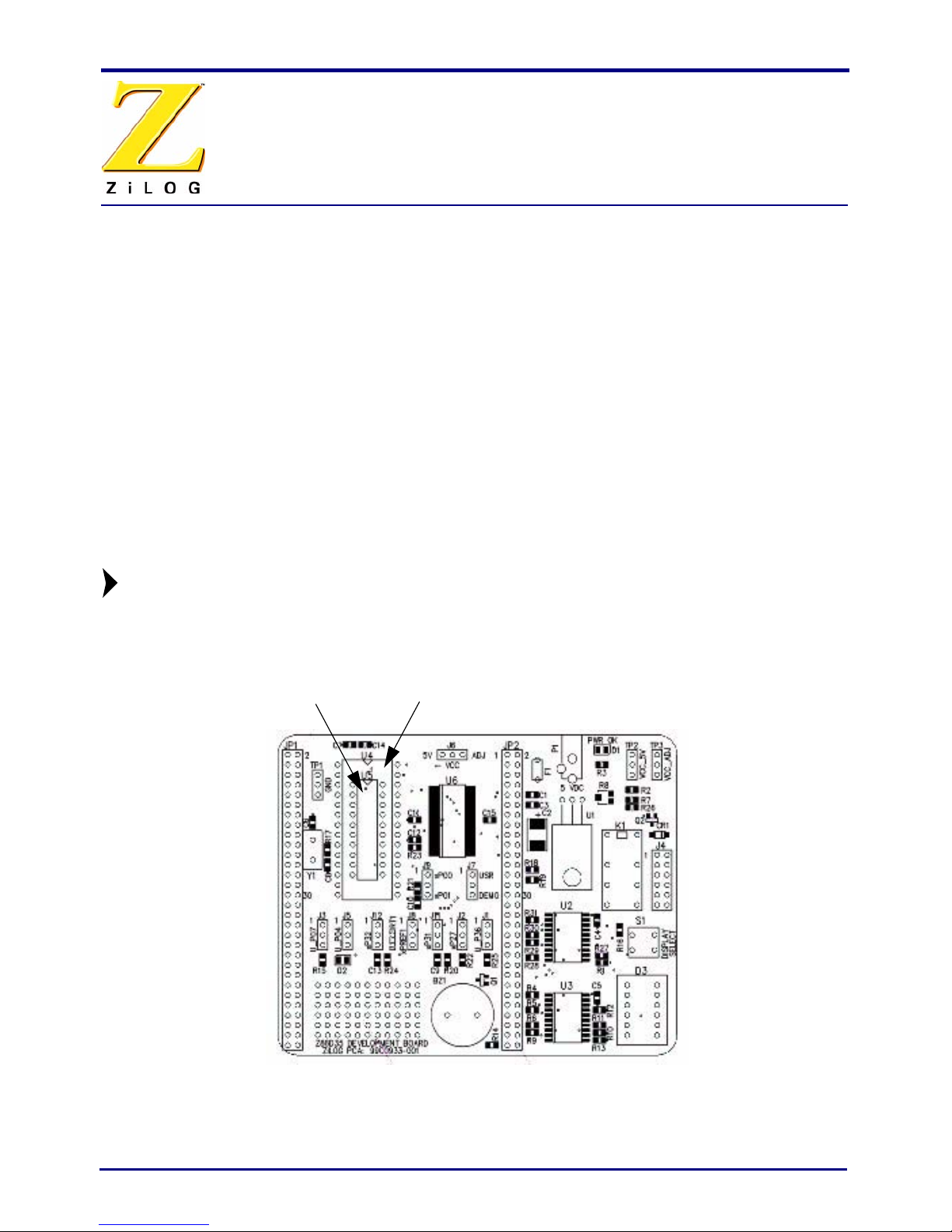
Installing a Target POD onto a Target Development Board
The Z8 GP ICE kit is ideal for use with a Z8 GP ZGP323 evaluation board (included, see
Figure 1) as a target development board. The 20-, 28, and 40-PDIP target PODs plug into
the associated PDIP sockets on the development platform.
If you are using a different target development board, use an appropriate target POD and
pin converter to connect the Z8 GP ICE to the board. For example, if your target board has
a 20-SOIC socket, mate the 20-PDIP target POD onto the 20-PDIP to 20-SOIC converter.
Then install the target POD and converter assembly into the board’s 20-SOIC socket.
If you are not using a target development board, insert the 34-pin null target
connector, p/n 93c0086-001, into Z8 GP ICE target interface connector P16.
Figure 1. Z8 GP ZGP323 Evaluation Board
Note:
20-PDIP 28-PDIP

Z8 GP™ ZGP323 In-Circuit Emulator and Development Platform
User Manual
Page 4
Install the Hardware UM019301-0505
Connecting the Z8 GP ICE to the Target POD
Once you have installed the appropriate target POD (and converter, if required) onto the
target development board, connect the Z8 GP ICE to the target POD as follows:
•40-PDIP target POD:
– Connect the 16-circuit cable from P17 on the emulator to P17 on the 40-PDIP tar-
get POD.
– Connect the 34-circuit cable from P16 on the emulator to P16 on the 40-PDIP target
POD.
•20-PDIP and 28-PDIP target PODs: Connect the 34-circuit cable from P16 on the
emulator to P16 on the target POD. (Emulator connector P17 is not used.)
Connecting the Z8 GP ICE to the OTP Programming Module (Optional)
After developing and debugging your software, use the following instructions to connect
the Z8 GP ICE to the OTP programming module so you can burn your code onto chips.
1. Connect the 40-circuit ribbon cable from the Z8 GP ICE OTP Programming connector
to connector P1 on the OTP programming module.
2. The 40-PDIP ZIF socket on the OTP programming module is designed to accept 40-
PDIP OTP chips. The OTP programming adapters (see Table 4 on page 24) allow you
to adapt the ZIF socket to accept 20-SOIC, 20-SSOP, 20-PDIP, 28-SOIC, 28-SSOP,
28-PDIP, and 48-SSOP chip packages.
Once you have installed the OTP chip into the ZIF socket (or programming adapter), you
are ready to program the chip using the instructions in “OTP Programming” on page 18.
Connecting the Z8 GP ICE to a PC
1. Connect a CAT-5 crossover cable from the PC to the Ethernet port on the Z8 GP ICE.
See Figure 2.
If you prefer, you can connect the emulator to an Ethernet hub using a stan-
dard CAT-5 patch cable.
Note:

Z8 GP™ ZGP323 In-Circuit Emulator and Development Platform
User Manual
Page 5
UM019301-0505 Install the Hardware
2. Connect the serial COM port on the PC to the SETUP serial port on the Z8 GP ICE
using the DB9-to-DB9 serial cable. See Figure 3.
Figure 2. Connecting a PC to the Z8 GP ICE
Figure 3. Z8 GP ICE Rear Panel
3. Connect a 5VDC power supply to the Z8 GP ICE. The 3.3VDC should illuminate (see
Figure 3). If the 3.3VDC LED fails to illuminate or the ICE Fail LED illuminates (see
Figure 5), there is a problem with the unit. Contact ZiLOG support at http://
www.zilog.com for a replacement unit.
Figure 4. Z8 GP ICE Top View
PC Z8 GP
ICE
CAT-5 Crossover Cable
DB9-to-DB9 Cable
J9
Out In
Target Trigger
1
J8
GND
1
J7
Int Target
CLK Source
1
OTP Programming
P17
P16
Target Interface
Target Interface
D1

Z8 GP™ ZGP323 In-Circuit Emulator and Development Platform
User Manual
Page 6
Configure the Hardware UM019301-0505
Figure 5. Z8 GP ICE Front-Panel
Configure the Hardware
Configuring the Z8 GP ICE consists of selecting emulator jumper options and setting up
Ethernet communications between the emulator and your PC.
Setting Jumpers on the Z8 GP ICE
There is one jumper on the Z8 GP ICE. Jumper J7 allows you to select whether the emula-
tor uses the target board clock or is programmable using the programmable clock settings
in ZDS II.
Table 2. Jumper J7 Settings on the Z8 GP ICE
Emulator... Jumper Position
uses the target clock. 1 - 2 (default)
uses the internal ZDS II
programmable clock.
2 - 3
ICE Fail LEDICE Run LED

Z8 GP™ ZGP323 In-Circuit Emulator and Development Platform
User Manual
Page 7
UM019301-0505 Configure the Hardware
Setting Up Ethernet Communications
The default IP address and subnet mask of the Z8 GP ICE are 192.168.1.50 and
255.255.255.0, respectively. To enable communication between the PC running ZDSII and
the Z8 GP ICE, you must either change the PC’s Ethernet settings to match those of the Z8
GP ICE or vice versa.
If using the PC in a stand-alone configuration, set the PC’s IP address to 192.168.1.21 and
its subnet mask to 255.255.255.0. See “Changing the PC’s Settings to Match the Z8 GP
ICE” on page 7.
In a networked environment, set the Z8 GP ICE IP address and subnet mask to match the
network setup. See “Changing Z8 GP ICE Settings to Match the PC” on page 11.
Changing the PC’s Settings to Match the Z8 GP ICE
After completing the following steps to change the PC’s Ethernet settings, proceed to Run-
ning a Sample Project on page 14.
The following instructions are for MS Windows XP. If your Windows operat-
ing system is different, refer to your MS Windows OS online help for details.
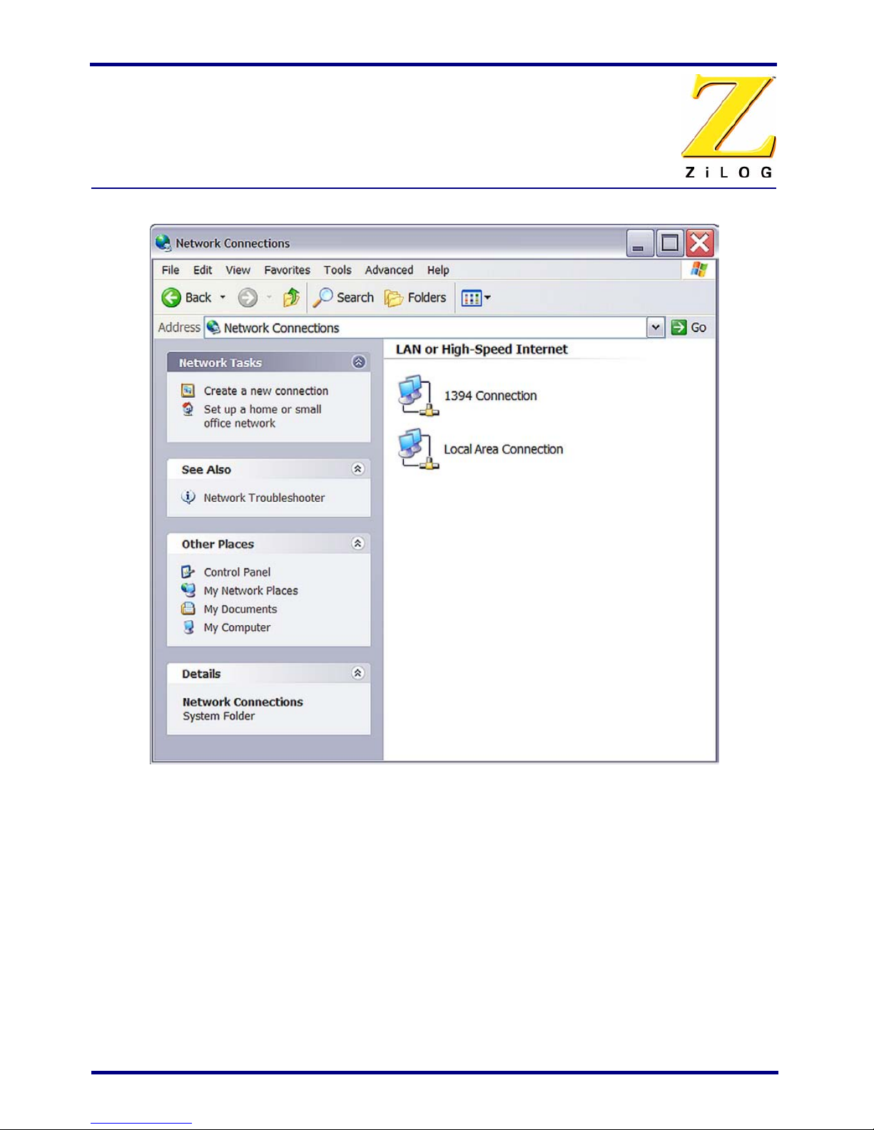
1. Open the Windows Control Panel and double-click the Network and Internet
Connections icon. The Network Connections dialog box appears (see Figure 6).
Note:

Z8 GP™ ZGP323 In-Circuit Emulator and Development Platform
User Manual
Page 8
Configure the Hardware UM019301-0505
Figure 6. The Network Dialog

Z8 GP™ ZGP323 In-Circuit Emulator and Development Platform
User Manual
Page 9
UM019301-0505 Configure the Hardware
2. In the panel labeled LAN or High-Speed Internet, double-click the Local Area Connec-
tion icon. The Local Area Connection Status dialog box appears (Figure 7).
Figure 7. The Local Area Connection Status Dialog

Z8 GP™ ZGP323 In-Circuit Emulator and Development Platform
User Manual
Page 10
Configure the Hardware UM019301-0505
3. In the Local Area Connection Status dialog box, click the Properties button. The Local
Area Connection Properties dialog box appears (Figure 8).
Figure 8. The Local Area Connection Properties Dialog

Z8 GP™ ZGP323 In-Circuit Emulator and Development Platform
User Manual
Page 11
UM019301-0505 Configure the Hardware
4. In the panel labeled This connection uses the following items:, select the Internet Pro-
tocol (TCP/IP) item to highlight it, and click the Properties button. The Internet Proto-
col (TCP/IP) Properties dialog box appears (Figure 9).
Figure 9. The Internet Protocol Properties Dialog
5. Enter values for the IP address and subnet mask to match those shown in Figure 9.
Leave any remaining fields blank. In this example, an IP address of 192.168.1.21 and
a subnet mask of 255.255.255.0 are being assigned to the PC. These values place the
PC on the same network as the Z8 GP ICE unit.
6. Click OK and restart the PC.
7. Proceed to “Running a Sample Project” on page 14.
Changing Z8 GP ICE Settings to Match the PC
1. Connect the PC serial port to the Z8 GP ICE serial port using the DB9-to-DB9 serial
cable.
2. Launch HyperTerminal on the PC by selecting Start --> Programs --> Accessories -->
Communications --> HyperTerminal.

Z8 GP™ ZGP323 In-Circuit Emulator and Development Platform
User Manual
Page 12
Configure the Hardware UM019301-0505
3. In the Connect To dialog, set the Connect Using: drop-down menu to match the COM
port to which the Z8 GP ICE is connected. Click OK.
4. A COM Properties dialog appears. Enter the following port settings and click OK.
Bits per second:57600
Data bits:8
Parity:None
Stop bits:2
Flow control:None
5. HyperTerminal should automatically attempt a connection. If not, select
Call --> Connect.
6. When the emulator is turned on or reset, HyperTerminal displays a Z8 GP ICE console
boot-up message in HyperTerminal. A typical boot-up message is shown below.
ZiLOG TCP/IP Software Suite v1.1
Copyright (C) 2004 ZiLOG Inc.
All Rights Reserved
clock enabled
IP Address: 192.168.1.50
IP Subnet: 192.168.1.0/255.255.255.0
IP Gateway: 192.168.1.254
Z8 ICE Firmware x.x (Dec 5 2003 13:45:05)
Copyright (C) 2001-2003 ZiLOG, Inc.
All Rights Reserved.
Press 'Ctl-Z' to enter configuration mode
7. Press ctrl-z. The emulator command prompt displays:
eth1 %
The emulator console prompt is not case-sensitive.
8. Type help or ? at the emulator command prompt to see a list of available commands.
The following list displays:
Commands are:
? debugport devs exit
help ifconfig kbuf kill
mem password ps reboot
restore
eth1 %
Command usage is described in Table 3.
Note:

Z8 GP™ ZGP323 In-Circuit Emulator and Development Platform
User Manual
Page 13
UM019301-0505 Configure the Hardware
Table 3. Z8 GP ICE Commands
Command Description and Options
? Displays available emulator command shell options.
debugport Configures the TCP port.Usage:
debugport – displays current setting
debugport tcp_port – sets debugport to specified TCP port.
Example:
debugport 4040
sets debugport to TCP port 4040.
devs not used
exit Exits the command shell.
help Displays available emulator command options.
ifconfig Configures the emulator network interface. Entering ipconfig with no
options lists current configuration.
The following command options are available:
• i – specifies an IP address
• s – specifies a subnet mask
• g – specifies a network gateway address
• dhcp – configures the emulator network interface to look for a dhcp
host to obtain network settings
Example:
ifconfig i 192.168.1.1 s 255.255.255.0 g 192.165.1.254
configures the emulator to use IP address 192.168.1.1 on subnet
255.255.255.0 with gateway address 192.168.1.254.
kbuf unused
kill unused
mem unused
password unused
ps unused
reboot Reboots the emulator.
restore Restores factory default network interface settings.

Z8 GP™ ZGP323 In-Circuit Emulator and Development Platform
User Manual
Page 14
Running a Sample Project UM019301-0505
9. When you have finished configuring the emulator, type exit to exit the command
shell.
10. Exit HyperTerminal.
11. Cycle the power on the Z8 GP ICE for the new settings to take effect.
12. The hardware is now configured and ready for application development.
Running a Sample Project
After installing the ZDS II software and setting up the hardware, you can run a sample
software project to verify proper emulator operation and experiment with the trace and
event system. This section describes how to run the emulator in in-circuit mode.
If you run the emulator with a target attached, be aware that the emulator’s
voltage comparator is designed as a target power sensor, not as a precision
voltage measurement device. If you set the Target VCC to match your target
and the target’s voltage drifts downward, the power sensor may no longer
detect it. The emulator may therefore not connect to the target. In such cases,
set the Target VCC voltage progressively lower until you get a good connec-
tion.
The sample project ledblink_c.pro is included in the ZDS II sample directory, located in:
c:\Program Files\ZiLOG\ZDSII_<product>_<version>
\samples\<processor type>_<demo name>
Start ZDS II for the Z8 GP ICE Emulator by opening Start > ZiLOG ZDS II-Z8 GP Emula-
tor Kit_<revision> and follow the instructions below to run ledblink_c.pro.
The C code example is used in the following description. An assembler ver-
sion is located in c:\Program Files\ZiLOG
\ZDSII_Z8GP_Emulator_Kit_<version>\samples
\ZGP323_ledBlink\ledblink_asm\src\ledblink_asm.pro.
1. Open the sample project file: File –> Open Project –>
c:\Program Files\ZiLOG\ZDSII_Z8GP_Emulator_<version>
\samples\ZGP323_ledBlink\ledblink_c\src\ledblink_c.pro.
2. Double-click main.c in the Project Files window.
3. Open Project –> Settings.
4. In the General tab, verify the CPU Family field is set to ZGP323.
Note:

Z8 GP™ ZGP323 In-Circuit Emulator and Development Platform
User Manual
Page 15
UM019301-0505 Running a Sample Project
5. In the General tab, set the CPU type field to ZGP323XXX2832.
6. In the Debugger tab, select Ethernet Driver from the Driver drop-down menu and then
click the Configure button.
7. The Ethernet Configure Driver dialog box appears. The IP Address field displays a
default IP address, 192.168.1.50. Enter the Z8 GP ICE IP address if it has been modi-
fied. Leave the Port setting at 4040.
8. Click OK.
9. In the Debugger tab, set the Target drop-down menu to ZGP323ICEXXZEM and then
click the Configure button.
The Configure Target window appears.
10. Set the Voltage drop-down menu to 3.0V. If the emulator is connected to a custom tar-
get, select the voltage appropriate for that target.
11. In Clock Source section, select the External radio button.
Ensure that jumper J7 on the Z8 GP ICE is set with the shunt between 1-2 as
described in Table 2 on page 6 when running the emulator in in-circuit mode.
12. In the Programming Option Bits section, ensure that none of the options are selected.
13. Click OK.
14. Click OK in the Project Settings window.
15. When asked to rebuild affected files, click Yes to rebuild the project. (You can also
rebuild later by pressing F7.)
The following steps describe two ways to use the trace and event system. For
details on running the trace and event system, refer to the ZDS II online help
and the ZDS II—Z8 GP User Manual (UM0178), located in the docs directory
of the ZDS II CD-ROM.
Collecting a Simple Trace
16. Now we’ll collect a simple trace by starting the program, then stopping it and viewing
the trace buffer. Click the Go button ( ) in the toolbar, wait a moment, and then
press the Break button ( ). The trace buffer acts as a ring buffer that continuously
fills and then overwrites itself until you stop execution.
17. Open the Trace window by selecting View > Debug Windows > Trace and then click
Get Frames to display the trace information.
Note:
Note:

Z8 GP™ ZGP323 In-Circuit Emulator and Development Platform
User Manual
Page 16
Running a Sample Project UM019301-0505
Using an Event to Stop Execution
Events allow you to stop execution based on more complex conditions than a simple
instruction address.
The following events are available:
•Program counter position, with mask.
•Data on Port0 (state of its pins), with mask.
•Data on Port2 (state of its pins), with mask.
•Data on Port3 (state of its three input pins), with mask.
•External Trigger In (0 or 1).
Let’s define a simple event and see how it works.
1. Select Tools --> Trace and Event System. The Trace and Event System window
appears (Figure 10).
Figure 10. Trace and Event System Window
2. Click the Enable Event System checkbox, and click the Break checkbox.

Z8 GP™ ZGP323 In-Circuit Emulator and Development Platform
User Manual
Page 17
UM019301-0505 Running a Sample Project
3. In the When: section, click the Program counter checkbox and set the Program
Counter to 06B2 and the Mask to FFFF.
4. Click OK.
5. Open the Trace window by selecting View –> Debug Windows –> Trace.
6. In the Trace window, click the Clear Trace button.
7. Reset the Debugger by clicking the Reset button in the toolbar, or by selecting
Build –> Debug –> Reset.
8. Run the Debugger by clicking the Go button or by selecting Build –> Debug –> Go.
9. When the program counter reaches 06B2, execution stops on event match.
10. Click Get Frames to display the trace information. Study the contents of the Trace
window to see how the trace and event system reports program execution for the seg-
ment we set using the Event tools.
Collecting Trace Before and After an Event
You can also use the Trace and Event System to capture trace data before and after an
event. Set up your events as described in “Using an Event to Stop Execution” on page 16.
In the Then: section, click the Event Position in Buffer radio button instead of Break. Use
the slider to select the number of cycles from the 64K buffer to be captured before and
after the event.
In this case, all cycles are traced until the event is detected, then the selected number of
cycles after the event are collected. Execution stops after the cycles are collected. What
remains in the trace buffer are the selected number of cycles after the event. The remainder
of the 64K frames contain cycles before the event occurred.
If you move the slider all the way to the left, only cycles before the event are captured. If
you move the slider all the way to the right, only cycles after the event are captured.
Single-Stepping Through a Program
ZDS II provides a simple mechanism for single-stepping through a program. To single-
step through a program:
1. Reset the program to Main() by either the Reset icon or with Build –> Debug –>
Reset. Set the Reset to Main option by selecting Tools –> Options. In the Options
window, select the Debugger tab and select the Reset to symbol ‘main’ checkbox.
2. To step through the program one instruction at a time, use F11 or click the button
in the Debug toolbar (also accessible by selecting Build –> Debug –> Step Into).

Z8 GP™ ZGP323 In-Circuit Emulator and Development Platform
User Manual
Page 18
OTP Programming UM019301-0505
Peek/Poke Registers
1. ZDS II makes it easy for you to set and read emulator register contents. With the
ledblink_c.pro project open and ZDS II connected to the emulator (target), select View
--> Debug Windows –> Registers.
2. In the Registers window, double-click the value of any register and type in a new
value.
3. Press Enter. The new value displays in red.
Refer to the ZDS II – Z8 GP User Manual (UM0178) on the ZDS II CD-ROM and the
ZDS II online help for further information on setting and reading register values.
Peek/Poke Memory
4. ZDS II also allow to set and read memory contents. With the ledblink_c.pro project
open and ZDS II connected to the emulator (target), select View –> Debug Windows –
> Memory.
5. In the Memory window, double-click the value you want to change and type in a new
value. (Values begin in the second column after the Address column.)
6. Press Enter. The new value displays in red.
Refer to the ZDS II User Manual (UM0178) on the ZDS II CD-ROM and the ZDS II
online help for further information on setting, filling, and reading memory.
OTP Programming
Once your program is running properly, use the Z8 GP ICE OTP Programming Module to
burn your program onto a ZGP323 family chip. There are two ways to burn an OTP chip:
•Burn the code in the current ZDS II project from emulator RAM onto the OTP chip.
•Load an existing hex file into emulator RAM and burn it onto the OTP chip.
Do not connect to the Z8 GP ICE when programming windowed CDIP parts.
Refer to “Burning Code from an Existing Hex File” on page 20 when pro-
gramming windowed CDIP parts.
Burning Code from the Current Project
To burn code from the project currently built in ZDS II (loaded in emulator RAM):
1. If you are currently in debugging mode, stop by clicking Build > Debug > Stop Debug
or pressing Shift-F5.
Note:

Z8 GP™ ZGP323 In-Circuit Emulator and Development Platform
User Manual
Page 19
UM019301-0505 OTP Programming
2. Connect the OTP programming module to the emulator as described in “Connecting
the Z8 GP ICE to the OTP Programming Module (Optional)” on page 4.
3. Select the OTP chip you wish to burn and the appropriate package converter.
4. Install the package converter, if used, into the ZIF socket on the OTP programming
module.
5. Install the OTP chip you wish to burn into the ZIF socket on the OTP programming
adapter. Match pin 1 of the chip with pin one of the ZIF socket.
6. In ZDS II, open the project for the code you wish to burn onto the chip.
7. Select Tools –> OTP Programming to open the OTP window (Figure 11).
Figure 11. OTP Programming Window (Current ZDS II Project Example)
8. If the appropriate target device is not selected, set it now in the Device drop-down
menu.

Z8 GP™ ZGP323 In-Circuit Emulator and Development Platform
User Manual
Page 20
OTP Programming UM019301-0505
9. If you do not want to pad the hex file, select the None button in the Pad File With area.
Otherwise, select the FF, 00, or Other button. If you select the Other button, type the
hex value to pad the hex file with in the Other field.
10. Click the Ram Checksum button to calculate the checksum of the data in emulator
RAM. Use this to compare with the OTP checksum after burning.
11. Select which option bits to program in the Programming Option Bits area.
12. If you do not want a serial number loaded into the part, select the None button in the
Method area. To load a serial number:
a. Select the Sequential or Pseudorandom button to determine how the serial number
is incremented on subsequent burns.
b. Select the size of the serial number (1, 2, 3, or 4 bytes) in the Serial Number Size
area.
c. Enter the starting serial number in the Serial Number field.
d. Enter the address into which you want the serial number loaded in the Address
field.
13. Click Blank Check to verify that the OTP chip is actually blank.
14. Click the Burn button to program the OTP chip with the contents of emulator RAM.
As part of the Burn function, the OTP chip is also verified.
15. When the burn is complete, click OTP checksum to calculate the checksum of data on
the OTP chip and compare it to the RAM checksum calculated earlier.
16. Click Close to close the OTP Programming window.
Burning Code from an Existing Hex File
To load an existing hex file into emulator RAM and burn an OTP:
1. Connect the OTP programming module to the emulator as described in “Connecting
the Z8 GP ICE to the OTP Programming Module (Optional)” on page 4.
2. Select the OTP chip you wish to burn and the appropriate package converter.
3. Install the package converter, if used, into the ZIF socket on the OTP programming
module.
4. Install the OTP chip you wish to burn into the ZIF socket on the OTP programming
adapter. Match pin 1 of the chip with pin one of the ZIF socket.
5. Stop any current debugging process by selecting Build --> Debug --> Stop Debug-
ging.
Other manuals for Z8 GP ZGP323
1
Table of contents
Other ZiLOG Motherboard manuals

ZiLOG
ZiLOG Z8F08A28100KITG User manual

ZiLOG
ZiLOG Z8 Encore! XP F0822 Series Flash MCU User manual

ZiLOG
ZiLOG GP ZGP323 ICE User manual

ZiLOG
ZiLOG Z8 Encore! User manual

ZiLOG
ZiLOG Z183 EMAC User manual

ZiLOG
ZiLOG Z51F0811 MCU User manual

ZiLOG
ZiLOG Z8 Encore! 8K/4K MCU User manual

ZiLOG
ZiLOG Z8 Encore! User manual