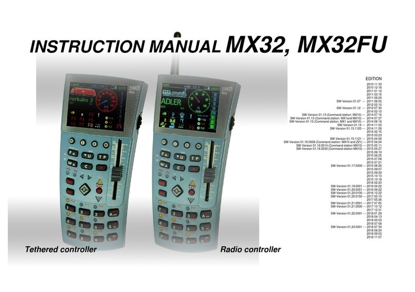
ZIMO MX31FU User manual

MX31 Cab, MX31FU Radio Cab Page 1
INSTRUCTION MANUAL EDITION
Production start, September 2005, SW-Version 1.01 2005 09 01
Corrections Nov. 2005, production start of MX31FU, SW-version 1.03 ---- 2005 11 25
REWRITTEN MAY 2006 (SW-Version 1.10; some pictures missing) --- 2006 05 01
Corrections and additions --- 2006 06 01
2006 07 01
Operating mode GUEST, SW-Version 1.12 --- 2006 11 03
This document will be
completed in the coming
weeks and months to include
display photos etc.
see www.zimo.at !
Tethered Radio
MX31 and MX31FU
Chapter
0. What’s new? since MX21 ...................................................................................2
. . . and what’s "old”? kept from the MX21 ............................................................................3
1. Introduction......................................................................................................................................................................4
2. Technical Information ......................................................................................................................................................4
3. Connecting cab’s to command station.............................................................................................................................4
4. QUICK GUIDE.................................................................................................................................................................6
5. Power up the MX31/MX31FU for the first time ................................................................................................................8
6. Power up OPERATOR, EXPERT................................................................................................................8
7. Address input OPERATOR, EXPERT ...............................................................................................................8
8. LOCO – mode OPERATOR................................................................................................................10
9. SWI - mode OPERATOR....................................................................................................................12
10. LOCO and SWI handling in EXPERT - Mode....................................................................................................14
11. LOCO and SWI handling in Guest Mode........................................................................................................15
12. Recall memory and list of names OPER., EXP. .........................................................................................................16
13. E - Procedures OPERATOR, EXPERT.......................................................................................................18
14. Programming OPERATOR, EXPERT............................................................................................................20
15. MENU and MENU FUNCTIONS OPERATOR, EXPERT ..................................................................................22
16. TEMPORARY: Definitions for TURNOUT LADDERS and AOS’s.............................................................................25
17. Radio operation with MX31FU & MXFU......................................................................................................................26
18. Glossary ......................................................................................................................................................................27
99. Preview of future software versions.............................................................................................................................28
Chapter 99: Preview to future software versions
IMPORTANT NOTES to SOFTWARE and SOFTWARE UPDATES:
Software that determines the characteristics and functions of this product is stored in a FLASH-
EPROM.
The current version may not yet be capable of all the functions mentioned in this manual. Installing
new software versions later can add new functions or correct recognized errors.
Current software is available at no charge from www.zimo.at (UPDATES). The software can be in-
stalled with the help of the program “ZST” (Zimo Service Tool) and a ZIMO command station MX1
“model 2000” or MX1EC. The ZST program is also available for download from the above web site at
no charge. A solution for updating systems with older command stations is in development.
Updates can also be performed by ZIMO at the expense of the customer (handling and shipping
fees). There is of course also no charge for the software itself. Updates performed by ZIMO are not
considered a warranty repair.

Page 2 MX31 Cab, MX31FU Radio Cab
0. What’s new?
since MX21
The MX31 tethered and MX31FU radio cabs replace the MX21 and MX21 radio cabs, which them-
selves were a further development of the MX2 and MX2FU respectively.
This chapter is placed ahead of the actual instruction manual and describes the substantial differ-
ences between the new MX31 cab and its predecessor, the MX21. It is not meant to be a complete
list of features -- because the MX21 was already equipped with ample features.
Some of the features described in this manual will be added later with software updates. These up-
dates can be down loaded at no charge from ZIMO’s web site www.zimo.at and installed with the
help of the ZIMO Service Tool (ZST). Updates are also necessary to correct software errors and
glitches that are unavoidable after a certain complexity is reached, to take customer experiences and
desires into consideration and to adapt the product to possible changes in industry standards.
Generous, future-oriented MX31 hardware
The user interface has been optimized and many important elements were added, without compro-
mising the proven basic layout of the previous cab:
LCD display 112 x 64 pixel, three-colored back ground illumination - readable in daylight – 26 keys –
1 slider – 1 thumbwheel encoder – 21 three-colored LED’s for functions and direction indication as
well as for the light bar – 6 LED’s for key illumination, yellow – 1 daylight sensor.
The MX31 is built for highest performance: 32 bit – 60MHz processor, 256KB Flash-EPROM, 16KB
RAM, 8Mbit serial Flash memory.
Three operating modes: GUEST - OPERATOR - EXPERT
ERXPERT from SW-Version 1.10, GUEST from SW-Version 1.12 (November 2006)
The OPERATOR mode is similar in presentation and range of functions to the MX21 but is easier to
read due to the larger display.
The GUEST mode limits the range of functions – usually limited to the control of one train so that
guests or children not familiar with the system won’t interfere with operations due to erroneous cab
inputs. This mode is password protected.
The EXPERT mode fully utilizes the technical possibilities with the maximum amount of information
displayed – up to 8 lines.
More than 12 functions
Implementation with future SW updates in 2006
This is useful for the many new features in today’s decoders and sound decoders. New NMRA RP’s
are in preparation.
Name allocation for complete trains and stations
Implementation with future SW update in 2006
Names can be used for single loco and accessory addresses – as was possible with the MX21 – but
also for consists. In this way, a double-header can be displayed with one name in large writing, fol-
lowed by the two loco addresses or names; for example: SAN ANTONIO and below EMD and SD40.
Provisions are made to comfortably switch between the locos of a consist for accessing individual
functions. The MX31 provides soft-keys for adding or subtracting (ADD, SUB) locos to/from a consist
– important for North-American operating methods!
Using names for routes containing several accessory addresses is also possible, which, in the future,
can also be displayed as small track schematics.
Icons and unlimited function key assignments
RG-key available with initial SW version, rest to follow with future SW updates in 2007
9 function icons can be displayed in grid formation (headlight, whistle, horn, turnout etc) in the lower
half of the display that not only identifies each key’s intended function but also its current state – the
latter is especially useful in direct sunlight where the function LED’s may be hard to see.
The user interface can further be enhanced by altering the effect of each number key from their stan-
dard function key assignments (including several function actuation with one key), so that a uniform
meaning of the keys can be achieved for all engines of a layout or for a certain class of engines.
Uniform shunting key “RG” – independent of decoder type
“low gear” operational with initial SW, rest to follow with future SW update in 2006
Shunting functions offered by many decoders (low gear, momentum turned off) are of practical im-
portance but are usually allocated to different function keys (F3, F4 etc.). The new “RG” key offers a
solution to this dilemma by allowing a flexible allocation of these functions to this uniform key.
Multi-level menu structure
Implemented with SW update 1.10
Several functions that were already available with the MX21 as well as new functions are now also
accessible through menus (if the key combinations are not known, e.g. name or route definitions).
There are 3 menu levels:
OPERATIONS menu for driving, turnouts, programming (e.g. list of names, shunting key allocation
etc.).
The SYSTEM menu for things like the system clock, command station CV’s and module CV’s (MX8,
MX9).
The CAB menu for language selection, dimming, timeouts, soft keys and much more.
Simultaneous display and handling of two applications
Implementation with future SW update is planned for 2006
With the cab in the EXPERT mode, the upper and lower halves of the display are assigned to two dif-
ferent tasks. For example: control of an engine (displayed in upper half) and simultaneous scrolling
through memory (displayed in lower half) or driving and simultaneous observation of an operating
sequence (an “AOS” E procedure); but, most of all, the simultaneous control of two engines as de-
scribed in the next section.
Simultaneous control of two engines (or trains)
Implementation with future SW update in 2006
While an engine is controlled with the primary controls of speed slider, direction key and function
keys, a second engine can be controlled using the encoder thumbwheel for speed and directions.
This is especially useful for shunting work or assembling/disassembling of consists.

MX31 Cab, MX31FU Radio Cab Page 3
Turnout actuation with soft keys in RUN mode
Implemented with SW version 1.10
A simple procedure enables the soft key’s I, II and III to control up to 30 turnouts (10 levels with 3
elements each) or turnout ladders, which can be actuated without switching over to the turnout mode.
Programming procedure with command line data storage
Implementation with future SW update planned for 2006
The programming commands are entered in clear-text format (e.g. „CV 5 = 180“), as before with the
MX21, in both the "service mode" (programming track) and "operations mode" (on-the-main). With
each further programming command entered, the previous commands slowly move up the screen
until they finally disappear altogether (similar to various computer applications). By scrolling through
this data bank, earlier command lines reappear in the display and can easily be selected and edited,
especially those that are applicable to other CV’s; compiling CV sets to be used with other addresses
is also greatly simplified.
“Bi-directional communication“, conceptually integrated
Implementation dependent on the standardization progress of the NMRA
The desired speed (cab setting) and actual speed are displayed numerically and also – for easy and
quick recognition – by the light bar next to the display, which additionally also shows speed limits ap-
plied by the “signal controlled speed influence” as well as “asymmetrical DCC” (Lenz ABC) with
flashing red LED’s.
Programming and read-outs performed in "operations mode" (on-the-main, on-the-fly) involves bidi-
rectional communication (provided the decoder and command station are equipped accordingly) to
ensure that these processes will be identical to the “service mode” programming on the programming
track.
Special emphasis is given to the transmission of “location codes“ and “routing codes” using bidirec-
tional communication, which are used by the ZIMO system for automatic route activation (including
the limited “ARS” version).
Easy control of automated operating sequences (AOS), automated route
sequences (ARS) ...
Implementation with future SW update planned for 2006
By displaying the currently controlled engine(s) and the AOS or ARS parameters at the same time, it
becomes easier to perform a definition or sample run with just one cab than it was with the MX21.
System data (track power etc.) displayed at the cab
Implemented with SW version 1.10; requires the right MX1 SW version
System data that is normally displayed at the command station only (volt, amps, CAN bus activity
and more) can now be displayed by the cab, if desired. This is also true for the MX1EC that doesn’t
have its own display (although one can be connected externally).
Multi-language support
Implemented with SW version 1.10
German or English can be selected as standard language (French and Italian may be added later);
add your own phrases with the help of the ZIMO Service Tool (ZST).
.
Radio cab with new battery technology
Radio cab MX31FU available in Europe since Fall of 2005
The MX31FU radio version will be equipped with a modern Lithium-Ionic battery, which markedly in-
creases the operating time in radio mode.
. . . and what’s "old”?
kept from the MX21 ...
Proven concepts and particulars of the previous cab generations MX2 and MX21 have been re-
tained: beginning with the table-top concept that allows the cab to be used as such or as a walk-
around throttle. The user interface layout and its handling has been modernized, optimized and heav-
ily extended but nevertheless retains many of the previous design features.
●Full DCC and MOTOROLA compliant
●Use of names for engines and turnout addresses
●Table display of recall memory and system memory
●Consisting without restrictions
●Comfortable programming in “service mode“ and “operations mode“
●and much more
●as has been the case with the MX21 already, new software versions can be installed with the help
of the ZIMO Service Tool (ZST) that is available together with new software at no charge from
www.zimo.at . The connection of the MX31 to the computer is also done via the command station
(MX1EC, MX1, MX1HS), which is equipped for this purpose with a serial interface.

Page 4 MX31 Cab, MX31FU Radio Cab
1. Introduction
This document describes the MX31 cab, the radio version MX31FU and the radio base module
MXFU.
The MX31 is designed to operate with the MX1 model 2000, MX1HS or MX1EC command station.
Certain restrictions apply when the MX31 is used with older command stations like the MX1/N and
MX1/MULT.
2. Technical Information
Current consumption (at 20 – 30 V CAN Bus power) ............................................. 20 - 50 mA
Current consumption of the MX31FU while charging the batteries........................................................
Dimensions Wfront – Wrear x Hfront – Hrear x L ................ 58 - 69 mm x 23 - 39 mm x 150 mm
Weight MX31..................................................................................................................................135 g
Weight MX31FU. .................................................................................................................. ...... 205 g
3. Connecting cab’s to command station
Each cab contains two identical sockets (internally parallel) for the CAN Bus connection to the com-
mand station. All cabs connected to the system (including different types) are connected in parallel,
usually by connecting a cable from the command station to the first cab and from there on to other
cabs, as shown below. Prefabricated cables in standard and custom length are available from ZIMO
(see pricelist), but can easily be homemade. The cable, connectors (50 per package) and the
required special pliers are also available from
ZIMO.
As an alternative to daisy-chaining the cabs, a 6-
conductor wire can be installed with outlets
around the layout. Distribution boxes are also
available (see ZIMO pricelist).
With most applications that have a maximum of
10 cabs and the total CAN bus length is limited to
150 feet (50m) no special considerations are re-
quired when connecting cabs to the command
station (For example: no more than 2 cabs at the end of a 150’ (50m) cable, no more than 5 cabs at
the end of a 60’ (20m) cable). If the number of cabs or the total CAN bus cable length exceeds these
limits, certain precautions have to be followed such as installing termination resistors (type. 150 –
330 Ohms) between the two center conductors at the end of the CAN bus and/or a separate power
supply for the CAN bus. Please contact ZIMO if necessary!

MX31 Cab, MX31FU Radio Cab Page 5
s
Hole for hook or nail Loop attachement
Cooling slots
D
A
YLIGHT SENSOR
Automatically adapts the display illumination and LED indicators
to the available light.
POWER SUPPLY SOCKET (MX31FU/MX31ZL only)
For charging the battery with an external charger, as an alterna-
tive to charging the cab through the CAN bus. Can also be used
for “back-up power” (when battery is empty), connected to the
track for example.
DISPLAY
Relevant information is displayed in various graphic renditions
depending on the operating mode selected. The display of the
“OPERATOR” mode is “cleaned-up”, while the “EXPERT” mode
shows as much information as possible.
The basic display pattern is:
- Active mode shown in top black bar (LOCO, SWI, PROG...),
clock;
- Current object displayed in large font (address, names etc.);
- EXPERT mode: center black bar displays feedback information
(radio, “bidirectional communication”);
- EXPERT mode: two display areas. Lower display half is used
for applications like previewing recall memory, operating a sec-
ond engine or displaying function icons.
GREEN background – LOCO MODE
RED background – SWITCH MODE
YELLOW background – INPUT MODE: Address, menu, list of
names, programming and more.
SOFTKEYS M I II III
Soft keys have different meanings depending on operating mode
and state and will be made visible in the display:
- The M key activates in most cases a menu - depending on the
level either status related, system related or cab related.
- I, II, III switches between operating mode (GUEST, EXPERT
etc.), selects the kind of information displayed in the lower dis-
play (recall memory, second address, pictogram etc.).
UPPER KEYPAD F U T P . . .
F, W: Activates entered address, also serves as scroll key (in-
stead of scroll wheel); starts programming procedure (operations
mode) when used together with E key.
U: “Stealing” address from other cabs; rotates through consist.
T: Consist activation/deactivation (Incl. Turnout ladders), proto-
col selection
C: “Cancel” key; when programming: CV selection
MN and RG keys with associated LED’s
MN (= MAN): Overrides signal controlled speed influence
(„asymmetrical DCC-Signals” as well); key E-MN pressed to-
gether starts service mode programming.
RG: Half speed key and/or shunting functions.
SHIFT KEY : Shifts to capital letters, functions F10 and up
(together with number key), emergency stop (together with stop
key) and more.
A
NTENNA TERMINAL (MX31FU only)
Accepts antenna supplied with cab.
2 CAN BUS SOCKETS
Connect to command station and additional cabs.
6-LED LIGHTBAR
- Light moves up or down to indicate the direction the slider has
to be moved to “catch” the actual speed of a newly acquired en-
gine and during a stop or emergency stop.
- Display of “signal controlled speed limits” sent back by the de-
coder (bidirectional communication) and more.
SCROLL WHEEL
Scroll and select data from recall memory, name tables, menus;
also used to control a second engine, analog functions and
sound parameters in sound decoders.
SLIDER
Controls speed of current engine or consist when in DRIVING
mode (LOCO), but also in ACCESSORY (SWI) or other modes
for the last activated engine address.
DIRECTION KEY WITH LED’s and STOP KEY
R: Direction key can also be used, like the slider, outside the
DRIVING mode. Direction indicated in relation to engine
(Fwd/Rev) or layout (East/West; taken from bidirectional
communications data).
S: Stop key for single address (press once); Emergency stop
(press several times!), turns track power off (after emergency
stop) and turns track power back on after short circuit.
“A” KEY
Activates addresses in table display or deactivates current ad-
dress (in EXPERT mode press -A);common “ENTER” or
“ACCEPT” key during programming and other procedures;
“YES” key; “ON” switch for radio cab, when operated in radio
mode.
“E” KEY
Initiates programming procedures or “E” procedures (when im-
mediately followed by or pressed together with another key);
common “END” or “ESCAPE” key to end programming, “E”
procedures, menu etc.; “NO” key as opposed to “A” key; Turns
off radio cab when pressed together with “A” key.
NUMBER KEYS with LED’s above
Depending on operating mode: Input of addresses, names, all
numerical values (during programming, definition); Actuate func-
tions (F0, F1 etc), accessories, turnout ladders, AOS’ and so
on; LED’s show state of function, AOS activation etc.

Page 6 MX31 Cab, MX31FU Radio Cab
4. QUICK GUIDE

MX31 Cab, MX31FU Radio Cab Page 7

Page 8 MX31 Cab, MX31FU Radio Cab
Start-up procedure of a new system or a cab containing no data:
5. Power up the MX31/MX31FU for the first
time
The cab is powered up automatically whenever it is connected to the CAN bus of a live command
station. The cab first enters
■the start up screen displaying the software version and the connection status;
■if a radio cab MX31FU, together with a MXFU radio base module is connected to the same CAN
bus, the cab displays the radio channel as set in the MXFU and the radio code number, which is
automatically picked by the MXFU. This confirms the initialization of the radio cab, meaning that it
will only be able to communicate with this command station but not with other command stations of
nearby layouts.
About 2 seconds later the cab automatically switches to the
■address input screen (see chapter „Address input“).
It is possible that the cab may switch directly to the driving (LOCO) or turnout (SWI) mode if a test
was performed on the cab earlier and the content wasn’t deleted before shipping. In such a case, the
address input page is reached by pressing the A key (=deactivates address) or pressing (repeatedly
if required) the C key (=deletes the address from memory).
Startup display for about 2 sec Address input page
Normal start-up procedure (without previous deletion of cab content):
6. Power up OPERATOR, EXPERT
The cab is powered up automatically whenever it is connected to the CAN bus of a live command
station with the exception of the radio cab MX31FU operated in radio mode, which is turned on with
the A key. With the
■MX31 and MX31FU tethered – the first screen shown is the start up screen, displaying the soft-
ware version and the connection status; shortly after (or immediately by pressing any key) it
switches to the mode that was active before the cab was powered down, that is usually to the driv-
ing (LOCO) or accessory (SWI) mode (see below).
■MX31FU in radio mode – it switches immediately to the mode that was active before the cab was
powered down, that is usually to the driving (LOCO) or accessory (SWI) mode (see below).
Startup display for about 2 sec LOCO display or SWI display
(tethered only)
7. Address input OPERATOR, EXPERT
WHEN?
▼at first start-up after the start-up display or
▼only in the OPERATOR mode with the “A” key deactivating the driving (LOCO) or accessory (SWI)
mode
▼in all modes including EXPERT mode with -A(shift and “A” key together), or
▼or from the LOCO or SWI menu (see chapter “MENU”).
From the OPERATOR mode
with “A” key
with -Akeys
to the address input page.
From the EXPERT mode

MX31 Cab, MX31FU Radio Cab Page 9
CAB?
■Display in yellow, waiting for an address to be entered indicated by the dots across the screen,
Key-LED’s are dark.
HOW?
♦Enter an address (1 ... 10239 for loco’s or 1 – 512 for accessory groups) using the number keys
1... 0; use P key first to select the appropriate protocol in case the address about to be activated is
for another format than DCC (M = MOTOROLA, D = DCC).
Activate address with the F key (mobile decoder) or W key (stationary decoder).
♦Special case: Enter a module address instead of a decoder address:
- 800... 863 for MX8 – ZIMO accessory modules
the address is entered as a four digit (!) number that includes a group number,
for example: 814/1, 814/2... where the forward slash is entered automatically
- 900... 963 for ZIMO MX9 track section modules.
Activate addresses for accessory modules or track section modules with the A key.
♦Use the C key to cancel incorrect entries.
Address input page…prompting to . . . enter address . . . after activation with the “F” key:
switches to address input menu
(press “F” again to enter LOCO mode)
. . . enter address . . . after activation with the “W” key:
switches to the SWI mode
. . . enter address . . . after activation with the “A” key:
module mode
The address input menu page only appears when an address is activated with the “F” key and
allows easy changing of the most frequently changed locomotive parameters right here instead of go-
ing to the programming mode first, which could, of course, also be changed later with the E-
procedures or through MENU.
Skip the address input menu by pressing the “F” key twice, if no changes are to be made. The
screen immediately jumps to the LOCO mode.
Either activate address without changes with
the “F” key or use the scroll wheel to select an
item from the list, press “A” and make changes,
return with “A” or “E” and finally activate
address with the “F” key.
Address input menu LOCO mode
WHERE TO?
►after activating a loco address by pressing the F key twice -> LOCO mode (green display), or
►after activating an accessory address with W key -> SWI mode, display turns red, or
►after activating a module address with A key -> SWI mode (MX8) or MX9 mode.
►ALTERNATIVE: The name table can be called up at any time, if names have been entered
earlier, with the key combination E-4 (press and hold E key followed by number 4 key); use
the scroll wheel (or F and W keys) to select a name and activate with the A key. Also see chapter
11: “recall memory and name tables”.
press E-4 . . . …select and
activate with A
List of names LOCO mode
►Cancel and return to the last active LOCO or SWI mode:
- by deleting all the input with the C key and activating the last address with the A key,
- or by pressing the E key at any time.
ACTIVATION FAILED?
Address starts flashing after attempted activation because this address is already active on an-
other cab, a computer or a PRA (PDA with PRA software) as either a single engine or as a consist.
The address may also flash if it is involved in an automated operation with AOS, ARS, or STP etc.:
Force take-over with U key, or
Use C key and select another address.
Module address (800... 900 ...) does not activate (no change-over to SWI or MX9 mode, display
remains yellow), because the module in question was not found on the CAN bus:
Cancel with C key and enter new address, or
Exit address input page with E key.
Address input menu from
SW version #1.10 on!

Page 10 MX31 Cab, MX31FU Radio Cab
8. LOCO – mode OPERATOR
WHEN?
▼immediately after power-up, if LOCO mode was active before last shut-down, or
▼activating an address with the F key during address input, or
▼scrolling through the recall memory using the F key, or
▼switching from the SWI mode to the LOCO mode with the F key, or
▼activating an address with the A key from the tabular display of the recall memory, or
▼activating an address name marked with an “F” from the list of names using the A key, or
▼after exiting E-procedures, programming and similar with A (Accept) or E (End) key.
From the address input page . . .
with F
with A
From the tabular display . . .
(recall memory, list of names,
see chapter “Recall memory”) . . . to the LOCO mode
CAB?
■Green display shows:
Top bar: “LOCO”, number of addresses in recall memory and fast clock;
Center: loco address (or name and address), consist indicator “T” where applicable;
Bottom bar: battery and radio signal strength (only with MX31FU in radio
mode), soft key ID’s and applied speed steps (“s…”);
Complete cab (keys, slider, LED’s) is dedicated to the control of the activated
loco.
HOW?
♦If the LED’s in the light bar next to the display are scrolling up or down, follow
with the slider in the indicated direction until they stop scrolling. This matches the
speed slider to the actual speed of the activated engine. Alternatively move the
slider to zero and press the Skey to stop the train.
♦Control the active engine using all cab elements: speed slider, direction key “R”,
Stop key “S”, keys “MN” (MAN) and RG (shunting) as well as all number keys
(1 … 0 = F0 … F9) as function keys; corresponding indicators in the
display and with LED’s above each key:
Direction key, stop key,
speed slider (with light bar
to the left, not visible in this
picture)
The light bar (6 vertical LED’s next to the display) normally moves
with the speed slider. It also visualizes system controlled acceleration
and deceleration functions, indicates the direction the speed slider
has to be moved to “catch” the speed of an acquired engine and
displays speed limits (red LED’s labeled with L, U, H) provided the
loco decoder sends information back via the bidirectional
communication (= RailCom).
The driving direction is switched with the direction key R and indi-
cated in two ways: the usual engine related way with two LED arrows
marked “Fwd” and “Rev”. The arrows also change colors to indicate
active brake and stop functions during change of directions. The
second way to indicate direction is layout related and is shown with
two smaller LED arrows marked “W” and “E” (for West, East). These
indicators are only active if previously set in the LOCO menu or if the
required information is received from the decoder with bidirectional
communication.
To stop an active engine immediately, overriding any programmed momentum, use the stop
key S.
New stop and broadcast stop handling from
SW-Version 1.10 !
A broadcast stop that stops all engines on a layout is issued when pressing the -S (shift and
stop key together) or by 3 x S that is, pressing the stop key three or more times within 1 second.
A single stop is indicated with a flashing red LED at the light bar and a flashing “STOP” in the
display, a broadcast stop also with a flashing red LED at the light bar and a flashing “General
Stop” in the display.
Activating the -S again (shift and stop key together) while in a broadcast emergency stop
mode (“General Stop”), turns track power off (“POWER OFF” in display).
Return to normal operation by pressing the stop key Sonce from any emergency stop or
“power off” mode as well as from short circuits indicated with “SH-CT MAIN “ or “SH-CT PROG“;
after a 3 second time period has elapsed since stop key was used to initiated emergency stop.
Chase lights move up (green) or down
Single stop (after pressing S) Broadcast stop (after pressing -S or 3xS) Track power off (after -S)

MX31 Cab, MX31FU Radio Cab Page 11
The RG key accesses shunting functions and, if not assigned differently,
splits the speed range of the speed slider in half that is, with the speed
regulator at full throttle the loco travels only at half throttle. The RG key is de-
fined in the LOCO menu and is most often used for shunting speed functions
of decoders (often with F3, F4 or other key) but also to reduce/suspend mo-
mentum as per CV #3, 4 etc.
The MAN function, MN key, eliminates the ZIMO “signal controlled speed
influence” or other methods of “location dependent control” (asymmetrical
DCC, Lenz “ABC”). The accompanying LED blinks when the MN function is active that is, the
speed limits are cancelled. The MAN function is used to drive past red signals during shunting,
train movements without routes in secured areas that otherwise wouldn’t be possible etc. The
MAN function normally sends a special ”override speed restriction” command to the decoder but
other modes of action can also be assigned to the MN key in the LOCO menu.
NOTE: The MN key only works with decoders equipped with that function, at this time (2006) only
with ZIMO decoders!
The function outputs of a decoder (headlights etc) are
switched with the number keys that operate as function keys
F0, F1, F2, … For F10, F11, F12, … (with future software
versions up to F19)press and hold the shift keyfirst.
The LED’s above the number keys indicate the state of the
outputs (no LED for F9). Each function key can be changed
from its default “always on” setting (= press function key turns
function on, press again to turns off) to a momentary setting (=
function is on only as long as the function key is pressed), with
the help of the E-procedure “MD” or via the LOCO menu.
With the T key, an active locomotive can be added to a consist, indicated in
the display with a “T” to the right of the address. All locos stored in the recall
memory of the cab that are marked with a “T” belong to the same consist and
are controlled simultaneously with the speed slider, direction key R, stop key
S, shunting key RG and MAN key MN, regardless of which address is currently
displayed as active in the display or which loco is the lead loco.
Use the F key to scroll through the individual consist addresses (all addresses marked with a
“T”) or use the tabular display of the recall memory by double-clicking the A key.
Remove a locomotive from a consist by pressing the T key again with the relevant loco address
displayed as being active.
♦The actual meaning of the soft keys for most situations is indicated
in the display (e.g. EXPERT, GUEST or switching of assigned turn-
outs), with the exception of the soft key “M”, which usually serves to
open the context sensitive menus. For example, pressing the “M” key in the LOCO mode opens
the LOCO menu at first and from there branches off to the SYSTEM or CAB menu, if desired.
WHERE TO AND BACK? (current loco remains active and returns cab to the LOCO mode again)
►Start an E-Procedure with key sequence E-x (E, followed by the key for the appropriate E-
procedure), use the “A” key to accept the changes made and exit E-procedures or use the “E” key
to exit without any changes taking place,
►E- MN (press and hold “E” followed by “MN”) starts programming (see chapter “Programming”) in
service mode (SERV MODE PROG on the programming track), exit programming with the “E”
key,
►E- F or E-W (press “E” together with the “F” or “W” key) starts programming (see chapter “Pro-
gramming”) on the main (OP. M. PROG), exit with “E” key.
►The soft key M opens the MENU (see chapter “MENU and MENU functions”); return with the E
key if no other state is entered with the selected menu item (may need to be actuated several
times).
WHERE TO? (current loco address will usually be deactivated)
►Deactivating current address with the “A” key (or -A) -> changes cab to Address Input mode
(yellow),
NOTE: use of A key is only possible in OPERATOR mode – in EXPERT mode use -A, or
►Deactivate current address and activate next address from the LOCO recall memory with the
“F” key (which is the loco that was deactivated last) or
►Deactivate and delete current address (from recall memory) with the “C” key. Also activates the next
address automatically from the recall memory (same as with “F” key), or
►Deactivate current address with the “W” key -> switches to the SWI mode (red), whereby
the last active accessory address (or switch ladder) will be activated, or
►Open the recall memory table (LOCO RECALL MEM) by pressing the “A” key twice (press key
twice within half a second) -> Tabular display of the recall memory (green), “A” key activates selec-
tion and “E” key exits; see chapter “recall memory”, or
►Open the LIST of NAMES with simultaneous E-4 (press “E” ahead of “4” key) or A+A+4 (in se-
quence) -> Tabular display of names (yellow) for engine and turnout addresses, “A” key activates
selection and “E” key exits; see chapter “recall memory and list of names”.
….A key
From the LOCO mode with … …to the address input page
….F key (rotate through memory)
….A + A key (tabular display)
to other engines in recall memory … …direct …via tabular display

Page 12 MX31 Cab, MX31FU Radio Cab
9. SWI - mode OPERATOR
There is a similarity between the SWI-mode and the LOCO-mode which means that the operation is
much the same. There are, however, some differences as indicated below..
WHEN?
▼immediately after power-up if cab was in the SWI-mode before the last shut-down, or
▼activating an address with the W key during address input, or
▼scrolling through the recall memory using the W key, or
▼switching from the LOCO mode to the SWI mode with the W key, or
▼activating an address with the A key from the tabular display of the recall memory, or
▼activating an address name marked with a “W” from the list of names using the A key, or
▼after exiting E-procedures, programming and similar with A (Accept) or E (Escape) key.
From the address input page . .
with W
An accessory address from 1 to 512 (address range for accessory de-
coders) can also control up to 8 single functions (e.g. uncoupler or
single light bulbs/LED’s of signals), one function for each number key
from 1 to 8. This operating mode is programmed for an accessory ad-
dress with the help of the E-procedure “9” or via the SWI menu.
with A
From the tabular display . . .
(recall memory, list of names,
see chapter “Recall memory”) . . . to the SWI mode.
CAB?
■Red display shows:
Top bar: “SWI”, number of addresses stored in recall memory (R …), fast clock,
Center: accessory address (or name and address), switch ladder indicated with an “H” if applica-
ble,
Bottom bar: battery and radio signal strength (only with MX31FU in radio mode), soft key ID’s and
applied speed steps (“s…”);
Number keys 1 to 4 or 1 to 8 (depending on decoder or module type) are used to operate
switches, signals etc., for the active accessory address. LED’s above keys indicate status of ac-
cessories.
The locomotive that was active last remains active in the SWI mode and can be controlled with the
speed slider, direction key, stop key, and MN and RG keys. Engine status is indicated with light
bar, LED’s for direction, MN and shunting (RG); see chapter LOCO – mode.
HOW?
♦Accessories (switches or signals) are operated with the number keys and the current setting is dis-
played with the accompanying LED; 4 or 8 keys are used depending on the kind of accessory, the
kind of decoders or modules and the operating mode selected
Each active accessory address from 1 to 512 (address range for ac-
cessory decoders), controls up to 4 paired functions (switches or
red/green signals) that are connected to one or several accessory de-
coders: Each key from 1 to 4 switches one turnout, switch position (or
signal status) is indicated with LED above respective key in red/green.
This is the most frequent and standardized form of accessory operation.
NOTE: The keys 5 to 8, which are normally unused for the 4 paired
functions, can be assigned for a second accessory address in the
EXPERT mode, which allows actuation and control of up to 8 turnouts.
This saves a lot of unnecessary switching between decoder addresses
and makes operation easier and more fun. After a second accessory
address has been assigned in the EXPERT mode it can also be used in
the OPERATOR mode! See SWI status in EXPERT – Mode.
If single functions are selected, each number key can operate in either
the default mode “always on” (= press function key turns function on,
press again to turn off) or the momentary mode (= function is on only as
long as the function key is pressed), with the help of the E-procedure
“MD” or via the SWI menu.
Each module number between 800…. 863 breaks up into several
groups, for example 814/2, 814/3, 814/4 because an accessory module
can for example be used to control 16 turnouts (2 groups of 8 turnouts
each) or 32 light bulbs/LED (4 groups of 8). Each group of 8 can then
be actuated with the 8 function keys on the cab. It is easy to scroll
through and select from the different groups stored in the SWI-recall
memory with the W key.
A group normally controls up to 8 paired functions (switches or
red/green signals) that are connected to the outputs of that MX8 group:
each number key from 1 – 8 controls one switch or signal, position or
signal status indicated with red/green LED.
First group of 8 Second group of 8

MX31 Cab, MX31FU Radio Cab Page 13
A group can also control up to 8 single functions (single light bulb/LED, uncoupler etc.), This is
why it is necessary to divide the module outputs into corresponding groups during address pro-
gramming (e.g. 4 groups with 8 single functions each, 2 groups with 8 paired function each or 2
groups of single functions and 1 group of paired functions), because with 8 single functions each
output requires its dedicated key whereas in the paired mode one key controls two outputs. See
chapter “Module Programming” and the MX8 manual for details.
If single functions are selected, each number key can operate in either the default mode “always
on” (= press function key turns function on, press again to turn off) or the momentary mode (=
function is on only as long as the function key is pressed), with the help of the E-procedure “MD”
or via the SWI menu.
♦True position feedback can be utilized by the cab if the accessory decoder or module supports it
and the turnout actuator is equipped with end switches. This feature is activated with the E-
procedure M/D (for each key separate).
The feedback information is sent to the MX8 using the CAN bus, via bidirectional communication
(= RailCom) or ZIMO acknowledgments in case of accessory decoders. The cab’s LED of a thrown
turnout keeps flashing until the appropriate feedback is received. Continuous flashing therefore in-
dicates that the turnout didn’t operate as expected.
♦The function of each soft key is marked in the display for most situations; e.g. switching between
the EXPERT and GUEST mode or operating turnouts defined for soft keys etc; with the exception
of soft key M, which almost always leads to a menu: the LOCO menu when in the LOCO mode,
from there to other menus if desired such as the SYSTEM or CAB menu.
Standard prompting for Turnout switching
EXPERT mode with soft key III using soft keys
WHERE TO AND BACK? Current address remains active, returns to SWI mode when finished.
►Start an E-Procedure with key sequence E - x (E, followed by the key for the appropriate E-
procedure), use the “A” key to accept the changes made and exit E-procedures or use the “E” key
to exit without any changes taking place,
►E- MN (press and hold “E” followed by “MN”) starts programming in service mode (SERV MODE
PROG on the programming track), exit programming with the “E” key,
►E- F or E - W (press “E” together with the “F” or “W” key) starts programming on the main (OP. M.
PROG), exit with “E” key.
►The soft key M opens the MENU (see chapter “MENU”); return with the E key if no other state is
entered with the selected menu item (may need to be actuated several times).
WHERE TO? Current address will be deactivated.
►Deactivate current address with the “A” key (or -A) -> changes cab to Address Input mode
(yellow), NOTE: use of A key is only possible in OPERATOR mode – in EXPERT mode use -A,
or
►Deactivate current address and activate next address from the recall memory with the “W” key
(which is the address that was deactivated last) or
►Deactivate and cancel current address (from the recall memory) with the “C” key. Also activates the
next address automatically from the recall memory (same as with “W” key), or
►Deactivate current address with the “F” key -> switches to the LOCO mode (green), whereby the
last active loco address (or consist) will be activated, or
►Open the recall memory table (SWI RECALL MEM) by pressing the “A” key twice (press key
twice within half a second) -> Tabular display of the recall memory (red), “A” key activates selec-
tion and “E” key exits; see chapter “recall memory”, or
►Open the LIST of NAMES with simultaneous E-4 (press “E” ahead of “4” key) or A + A + 4 (press
key A twice followed by the #4 key) -> Tabular display of names (yellow), “A” key activates selec-
tion and “E” key exits; see chapter “recall memory and list of names”.
… “A”
From the SWI mode with…. …to the address input page
…. “W” (rotate through memory)
….A + A key (tabular display)
to other accessoris in recall memory … …direct …via tabular display

Page 14 MX31 Cab, MX31FU Radio Cab
10. LOCO and SWI handling in EXPERT -Mode
When changing from the OPERATOR to the EXPERT mode, the first thing noticed is that the whole
OPERATOR screen shrinks by using smaller fonts so that it will fit in the upper half of the display.
The speed regulator position (“s…”) will be moved from the lower black bar to the upper. The lower
display half can now be used for further information.
Switching from the OPERATOR to the
EXPERT mode
with the soft key as prompted in the lower
black bar, usually with Soft Key III.
LOCO display in OPERATOR LOCO display in EXPERT with preview
of LOCO recall memory and soft key prompts
If no soft key is indicated for switchover, the MENU can be used instead to change to a different
mode! Switching back (from the EXPERT to OPERATOR mode) is also accomplished with a soft key
(“OPER”) or via the menu.
Using the cab in EXPERT mode is identical to the OPERATOR mode (driving, switching of func-
tions and accessories).
EXEPTION: DEACTIVATION of an active address (to get to the address input page in order to en-
ter a new address) is not possible with the “A” key, because this key is used in connection with the
recall memory preview, see below. Only the key combination -A (shift and “A” together) deactivates
an address!
There are numerous ways to use the free space in the lower display half. Not all of them will be
available from the start but will be added one by one with future software updates.
Recall memory preview with direct activation
This is the standard application of the EXPERT mode: 3 lines from the recall memory are displayed
beneath the center bar, selectively from the LOCO or the SWI recall memory.
See the chapter “Recall memory and list of names” regarding the recall memory’s purpose and mode
of action!
Use the scroll wheel to search through the recall memory preview.
Switch between the LOCO recall memory and the SWI recall memory with the soft key indicated in
the lower right corner of the display (usually II).
Use the A key to activate a marked address, which brings the address to the upper display half and
in control of the operator. If an address from the SWI recall memory is selected, the cab will of course
switch from the LOCO to the SWI mode (red display) or the other way around, if applicable.
Select and mark with the scroll wheel
Activate marked engine address
with the A key
EXPERT-Mode from SW-Version 1.10 !
LOCO mode EXPERT LOCO mode EXPERT
with LOCO recall memory preview . . . after selecting and activating of a marked engine address
Switch-over
to the SWI recall
memory preview
with soft key II
Select with scroll wheel
Activate with A key
LOCO mode EXPERT SWI mode EXPERT
with SWI recall memory preview . . . after selecting and activating of a marked address
CAB display of track voltage and power
The track voltage and power measured by the command station (MX1 and MX1HS, separate for
each track output) can be displayed in the center bar of the display when in EXPERT mode. This
must first be activated in the menu “ABOUT THIS CAB”.
See pictures above!
Note: The center bar will be used for other information with future software versions; most importantly
for the bidirectional communication (RailCom)!
Linking the active address with a secondary accessory address
The 4 paired functions of an accessory address in the SWI mode (usually turnouts) require only 4
keys of the cab, keys 5 to 8 remain unused in the OPERATOR as well as in the EXPERT mode.
„Secondary accessory address link“ is planned for SW-Version 1.20!
With the help of the “secondary accessory address link” it is possible to activate a second ad-
dress with keys 5 to 8 so that 8 turnouts can be controlled and operated at the same time.
Linking such a second accessory address is done, after selection with
the scroll wheel from the SWI recall memory preview, with the soft key
“2.-SWI” (usually I);
The second accessory address is now linked with the active address
in the upper display half and both are always activated together. Ac-
cordingly, both addresses are displayed together (“xxx + yyy”), if nec-
essary under the name of the first address.
SWI mode with SWI recall memory preview

MX31 Cab, MX31FU Radio Cab Page 15
The accessory addresses linked in the
EXPERT mode are equally valid in the
OPERATOR mode!
SWI display in EXPERT mode SWI display in OPERATOR mode
linked to a second accessory address linked to a second accessory address
Breaking such a link (deleting a linked secondary accessory address) is also possible only in the
EXPERT mode with the soft key ”2.-DEL”.
Use of Soft Key’s
The applicable assignments of the soft key’s I, II and III are indicated in the lower right corner of the
EXPERT mode display. This is by default the switchover to the OPERATOR mode, switching be-
tween the recall memory preview lists LOCO, SWI and more; see previous pages.
Soft keys can also be defined for other functions, via the menu, which are displayed accordingly at
the proper time in the display; i.e. switching of selected turnouts in the LOCO as well as in the SWI
mode.
The soft key assignment may be extended to 10 levels. For example: each soft key can control up to
10 turnouts for a total of 30. The 30 available slots may also be mixed for different functions. Moving
between the levels is done with the scroll wheel whereby the available levels are added automatically
to the recall memory preview lists that are displayed in the EXPERT mode.
Scroll to the end of the preview
list using the scroll wheel to
select from the soft key levels.
LOCO display in EXPERT mode LOCO display in EXPERT mode
with LOCO recall memory preview with the same preview list after scrolling down.
If the cursor points to an entry such as “Soft SWI Lev 1”, “Soft SWI Lev 2” at the end of the preview
table, the turnouts belonging to this level can be operated immediately with the soft keys.
11. LOCO and SWI handling in Guest Mode
GUEST- Mode from SW-Version 1.12 !
The GUEST mode can only be selected via the menu (LOCO or SWI menu). Press the soft key “M”,
scroll to GUEST mode, select with the “A” key and exit the menu with the “E” key.
First applications (turnout actuations with soft keys) from SW-Version 1.10! LOCO display – OPERATOR MENU after GUEST selection LOCO display – GUEST
A number of functions are locked out in the GUEST mode:
Deactivation, which includes address input,
Activation of modules such as MX9, MXDS,
Switch ladders, AOS etc.,
Recall memory list, list of names, menus,
E-functions,
Programming in service mode (E+MAN) as well as operations mode (E+F, E+W),
EXPERT mode,
Keys C, T, RG
NOTE and TIP: It is still possible though in the GUEST mode to switch to the next loco address or
the next group of switches with the keys F or W, provided the recall memory of the cab holds more
addresses. If the GUEST mode is to be limited to one address only, delete all other addresses from
the cab before entering the GUEST mode!
The GUEST mode can be exited with the help of the soft key III, but only after entering a secret
code number (PIN)! By default, this number is 0 and is therefore not necessary to enter when
prompted to do so (just acknowledge with the “A” key).
An actual secret code number that needs to be entered before exiting the GUEST mode can be de-
fiend under PIN in the menu ABOUT THIS CAB.
In case the defined number was forgotten, a master code number can be obtained from ZIMO.

Page 16 MX31 Cab, MX31FU Radio Cab
12. Recall memory and list of names OPER., EXP.
The recall memory (a local memory in the cab):
If a loco or accessory address in a cab is deactivated (“A” key or - A) it does not disappear from the
system but remains stored in the recall memory of the command station and the relevant cab (MX2,
MX21, MX31….).
By default, the recall memories of the MX31 hold 10 addresses in each mode, LOCO and SWI (the
size of the memory can be changed to hold between 1 and 30 addresses with the help of the E-
procedure RUB or via the menu). How many addresses the memory currently holds is indicated in
the top line of the display (“R...”) in both, the LOCO and SWI mode.
All ZIMO cabs will bring the top address stored in the recall memory to the foreground and activate it
with the F key S(LOCO mode) or the - W S(SWI mode) while at the same time deactivate the
previous address. Repeatedly activating the F or W key rotates through the complete memory bank.
Additionally, with - F S(shift and F key) or - W Sthe recall memory can be rotated through in
reverse, which can sometimes be very useful.
The U ▼key will always get you back to the last active address, i.e. to move quickly and easily be-
tween two loco or accessory addresses.
The C key deletes the currently active address from the recall memory!
In the ZIMO cabs MX21 and MX31: Pressing the A key twice in rapid succession (within half a sec-
ond) while in an active LOCO or SWI mode switches to a tabular display of the recall memory (not
available in MX2 cab), listing names and addresses including the data format and if applicable marK-
ers for consists (“T”) or switch ladders (“H”). The list can be scrolled Up or down with the thumb
wheel (not available with MX2 or MX21 cab) or the F and W keys and the desired selection acti-
vated with the “A” key. Using the E key instead leads to the previously active address.
Change to the tabular display with
A + A (press A key twice)
Return with selected engine with the A key
or to previous address with the E key.
LOCO display in OPERATOR mode Tabular display of the recall
memory in the LOCO display
Change to the tabular display w
A + A (press A key twi
Return with selected turnout with A key
ith
ce)
SWI display in EXPERT mode Tabular display of the recall memory
or to previous address with the E key.
in the SWI display
The tabular display can be called up in the OPERATOR mode as well as the EXPERT mode. The
presentation differs in the font size and therefore also in the number of lines visible in the display.
The EXPERT display also shows a “recall memory preview” in the lower display half: 3 lines from the
recall memory that can be scrolled and activated similar to the full display view. See chapter “LOCO
and SWI handling in EXPERT mode”.
The list of names (currently implemented as a system wide feature):
In contrast to the recall memory, the list of names is not divided according to LOCO and SWI infor-
mation. It shows all names stored in the system on the same page and it shows names exclusively,
which means that numerical loco or accessory addresses are not shown in this list.
The list of names is displayed in a table format only and can be called up using the E- 4 keys (E and
4 key pressed together) or with A + A + 4 (press the A key twice followed by the “4” key). The
entries are marked with an “F” (for a loco address) or “W” (accessory address). The cab selects the
appropriate mode, either LOCO or SWI, when an entry is being activated with the A key.
The list of names is of particular importance in conjunction with acquiring names from other cabs or
the system. It functions as a cache: external names are stored in the list of names from where they
can be accessed and activated by any cab and are in this way imported in to a cab’s recall memory.
Change to the list of names with
E - 4 or A + A + 4
Return with new address with the A key
or to previous address with the E key.
LOCO display in EXPERT mode Tabular display of the list of
names in the LOCO display
Comparison table:

MX31 Cab, MX31FU Radio Cab Page 17
SUMMARY of the SELECTIONS:
WHEN? (to switch from the LOCO or SWI mode to the tabular display)
▼from the active LOCO mode, with A + A (2x A key)
to the tabular display of the LOCO recall memory
▼from the active SWI mode, with A + A (2 x A key) to the tabular display of the SWI recall memory
▼from the LOCO or the SWI mode, with E-4 (press E and 4 keys together)
or A + A + 4 (2 x A followed by 4)
to the tabular display of the list of names.
CAB?
■Display: green for the LOCO or red for the SWI recall memory table. Full-screen display.
■Display: yellow (List of names); Full-screen display.
HOW? (in the tabular display)
♦Scroll the table using the thumb wheel, F/ W keys (up/down) or the speed slider.
WHERE TO? (leaving the tabular display)
►Activate the selected address with the A key;
►Return to the previous (last active) address with the E key.

Page 18 MX31 Cab, MX31FU Radio Cab
13. E - Procedures OPERATOR, EXPERT
WHEN?
▼from the LOCO mode with the E key and the number key, marked with desired E-procedure
▼from the SWI mode with the E key and the number key, marked with desired E-procedure
All E-Procedures can also be called up using the menu, where the key combinations for above men-
tioned shortcuts are also shown.
Start of an E-Procedure,
for example: E-Procedure “NAM”
with E + 4 keys (in succession)
LOCO display in OPERATOR mode E-Procedure, in this example:
ready to enter a name after E+4
.
CAB?
■Display color of the selected mode remains (green or red), capital “E” displayed to confirm E-
procedure programming, beside it prompting and entry lines of the respective procedure.
The bottom display bar indicates the exit options: A = Accept, E = Escape.
HOW?
There are a number of different E-procedures available, named after the key that is pressed following
the E key.
All E-procedures are started with the E key, followed by another key that selects a procedure. Keys
that offer an E-procedure are marked accordingly just above the key; the two keys are pressed in
sequence, not together! The relevant information can now be entered or a selection made from the
list presented using the scroll wheel and exited with the A or E key.
WHERE TO AND BACK?
Exit: with A key (= Accept): Accepts the selections made with the E-procedures and returns to pre-
vious mode (LOCO, SWI or MENU); E key (= Escape): Returns to previous mode without imple-
menting selections made with E-procedures.
♦E-procedure 8/12 (press E - 1) – selects between the 8 and 12 function mode for the active
loco address; selection for this address remains stored in the system even after address gets de-
activated. This procedure is no longer relevant today, if all ZIMO components
(command station and decoder) in use were produced in 2003 or
later – they all operate in the 12 function mode by default. If on the
other hand ZIMO decoders from earlier productions are used and
functions above F4 and/or the MAN key employed, an adjustment
may be required that is, the relevant addresses need to be set to the
8-function mode with the help of the E-procedure 8/12. See the leaf-
let “8/12 functions” available on the Zimo web-site.
However, this procedure will gain new significance in the future (in the course of 2006) when the
new DCC standard with more than 12 functions will be introduced!
♦E-procedure PUK (press E + 2) – selects between “normal” and “serial” function actuation,
also known as “pulse chain commands”; selection for this address remains stored in the system
even after address gets deactivated.
This procedure is only relevant for older LGB locomotives
equipped with original LGB decoders (built before 2004) that oper-
ates function outputs with just one function key (F1) by sending dif-
ferent number of pulses for each function. The ZIMO command sta-
tion generates this pulse chain command automatically containing
between 2 and 8 pulses when function keys F2 – F8 are actuated, if
activated with the PUK E-procedure.
♦E-procedures AZ, BZ, ABK (press E + 3, 6 or 9) – Sets acceleration and deceleration rates
as well as specific characteristic curves for the active address; selection for this address remains
stored in the system even after address gets deactivated.
The acceleration and deceleration rates set with this procedure have
nothing to do with the decoder configuration variables (CV #3 and
4), but rather determines the succession rate of speed step com-
mands sent out by the system. Both system and decoder controlled
acceleration and deceleration rates supplement each other in the re-
sulting driving characteristic.
Values between 0 and 15 can be chosen for AZ and BZ, which is the
time in seconds it takes for an acceleration or deceleration event to
occur from a stand still to full speed or the reverse. ABK determines different characteristic curves
(shallower curve with values between 1 – 8 in the lower speed range or steeper with 9 – 15) with
fixed time elapse according to AZ and BZ.
♦E-procedure NAM (press E + 4) – to enter or edit names used for the active loco or accessory
address; allocated names remain stored in the system even after
address gets deactivated.
If a name is already allocated for this address, it will be shown in the
display and can be deleted letter by letter with the “C” key. Enter
names with the number keys that act as alpha-numerical keys, same
as with telephones.
NOTE: If the E-procedure NAM is started for an address belonging
to a consist or switch ladder (“T” marker in the LOCO mode or “H”

MX31 Cab, MX31FU Radio Cab Page 19
marker in the SWI mode display), the name entered is used for the consist (or switch ladder). From
SW-Version 1.20.
NOTE: Names containing up to 7 letters are displayed in large font as an active address, with me-
dium font if longer; 12 characters is the maximum that fits in one row but it is possible to use
names with up to 24 characters.
♦E-procedure M/D (press E + 7) – selects between permanent and temporary function key ac-
tuation of the active LOCO or SWI address; selection for this address remains stored in the system
even after address gets deactivated.
After entering this E-procedure, use the function keys to be changed
to toggle between temporary or permanent actuation; the LED’s
above the keys indicate the selection made: green for permanent and
red for momentary action.
All function keys by default are set to permanent action except for F9,
which is set to momentary because there is no indicator-LED avail-
able in the MX31 cab.
♦E-procedure RÜB (press E + 8) – defines the recall memory depth, separate for the LOCO and
SWI memory (for the mode this E-procedure was started from).
Every single address (as well as consist) is stored in the recall mem-
ory after its deactivation, from where it can be re-activated (in the
tabular address display or by directly rotating through the memory
with the F or W key). The recall memory holds 10 addresses by de-
fault. Once the memory is full, the oldest entry is dropped with every
new address added to the memory. The memory size can be
changed with the E-procedure RÜB to hold between 1 and 30 ad-
dresses.
♦E-procedure OS (press E + U) – shortcut to enter the area of operating sequences (can also be
reached using the menus), to define new or actuate stored switch ladders, automatic operating se-
quences (AOS), automatic routing sequences (ARS) and similar features to be introduced in the
future. Also see chapter about operating sequences!
♦E-Procedure STU (press E + 0) – Selects between 14, 28 or 128 speed steps.
28 speed steps are set by default, which means that decoders set to
28 or 128 speed steps are functioning properly. Not so with decoder
set to 14 speed steps (mostly older decoders or LGB; the incompati-
bility is usually recognizable by the flashing head lights).
To take full advantage of modern decoders (128 speed steps) set the
cab to 128 steps as well (for each single address with this procedure
or for all addresses via the menu).

Page 20 MX31 Cab, MX31FU Radio Cab
14. Programming OPERATOR, EXPERT
One part of programming is assigning a specific address to a loco or accessory decoder. This is
done in “service mode programming’, which is only possible on the programming track. The other
part of programming involves writing or modifying the data content of configuration variables (CV’s)
to a decoder.
Programming in
“Service mode” ”Operations mode”
Locomotive (or decoder) on programming (”on-the-main”,
track (output ”PROG”), Loco at standstill. output Loco at standstill or traveling.
Address CV programming. Only CV programming is possible.
Safe programming through acknowledgment. Unconfirmed programming (certain degree of
reliability by sending commands repeatedly).
Read-out of addresses and configuration Read-out not possible (CV read-out may become
variables possible. possible in 2006 via bi-directional communication).
Start programming with “E” and “MAN” key. Start with “E” and “F” or “E” and “W” key.
Loco (or decoder) on main track
”SCHIENE”),
and
When?
▼from the LOCO mode with E-MN (press E (first) and MN keys together) for
programming in „service mode“
▼from the LOCO mode with E-F (press E (first) and F keys together) for
programming in „operations mode“
▼from the SWI mode with E-MN (press E (first) and MN keys together) for
programming in „Service mode“
▼from the SWI mode with E-W (press E (first) and W keys together) for
programming in „operations mode“
Starting a programming procedure
(i.e. with E-MN)
LOCO display Programming display
CAB?
■Yellow display, capital “A” (“A” for Addressing) confirms that “Service mode” programming or “P”
that “operations mode” programming is active.
HOW?
♦After entering “service mode” programming (capital “A” in
display), the procedure starts with the prompt “ADDR = “, which
leaves two possible choices:
Punch in an address and confirm with the F key (for a loco de-
coder) or the W key (for an accessory decoder), after which the
address is written to the loco (with installed decoder) sitting on the
programming track or to a decoder connected directly to the pro-
gramming output of the command station. A successful program-
ming is acknowledged on the same line in the display with “ACK”.
An unsuccessful programming is indicated with an “Err …” mes-
sage.
ZIMO decoders initiate a “hard reset” when programmed to ad-
dress “0”. NOTE: This is only possible with ZIMO decoders. De-
coders of other manufacturers are reset by writing 8 to CV address
8. This procedure is also possible with ZIMO decoders giving two
choices to initiate a hard reset.
Pressing the “A” key immediately after the “ADDR …” line ap-
pears (without punching in an address), causes the command sta-
tion to read out the address of any decoder connected to the pro-
gramming output and displays it in the cab display, followed by the
confirmation “READ”. An error message (“Err ...”) appears if
read-out is not possible.
You can now overwrite an existing address, exit programming with
the “E” key or branch off to CV programming with the “C” key
(see below).
♦“Operations mode programming” (capital “P” in display) to
program CV’s commences immediately with the line “ADDR ..” as w
informational purposes since the address cannot be changed in op-
erations mode programming.
ell, but is only displayed for
♦Programming CV’s is identical in either “service mode” or “opera-
tions mode” (capital “A” or “P” in display):
Most often a CV number is already displayed as a suggestion,
which can be accepted by pressing the “A” key or deleted (with the
“C” key or simply overwritten) and entering a CV number, accept
with the “A” key (which is displayed as “=”),key in the desired
value and accept again with the “A” key.
Programming in “service mode” is acknowledged with the confir-
mation “ACK” or an error message (Err ..); actual confirmation in
“operations mode” programming will only be possible once bidirec-
This manual suits for next models
1
Table of contents
Other ZIMO Controllers manuals
Popular Controllers manuals by other brands

Parker
Parker 08R Series Installation and service instructions

Blaze
Blaze EVERCADE VS instruction manual

RKC INSTRUMENT
RKC INSTRUMENT THV-10 instruction manual

National Instruments
National Instruments sbRIO-9629 Quick reference guide

LUCCI
LUCCI GECKO 221080 installation instructions

WAREMA
WAREMA LONMSE 2M230 User and installation guide

Dwyer Instruments
Dwyer Instruments DCT500ADC Series Installation and operating instructions

EMRI
EMRI R10 Series operating instructions

Tormach
Tormach SmartCool Technical document

MRC
MRC VC-100 operating instructions

Russound
Russound WALTX-2 instruction manual

Lunatico
Lunatico AAG CloudWatcher Solo user manual