Zinwell ZPlus-B191-OD User manual

Wireless LAN Device Series
WLAN Outdoor Bridge
ZPlus-B191-OD User Manual
Version. 1.03 (07.15.2004)

1
Notice
“This device complies with Part 15 of the FCC Rules. Operation is subject to the following two
conditions:(1) This device may not cause harmful interference, and (2) this device must
accept any interference received, including interference that may cause undesired operation.
Warning:Changes or modifications to this unit not expressly approved by the party responsible
for compliance could void the user authority to operate the equipment.
This device complies with Part 15 of the FCC Rules. Operation is subject to the following two
conditions:(1) This device may not cause harmful interference, and (2) this device must
accept any interference received, including interference that may cause undesired operation.
The user’s manual or instruction manual for an intentional or unintentional radiator shall caution
the user that changes or modifications not expressly ODU proved by the party responsible for
compliance could void the user’s authority to operate the equipment.
NOTE:This equipment has been tested and found to comply with the limits for a Class B digital
device, pursuant to Part 15 of the FCC Rules. These limits are designed to provide reasonable
protection against harmful interference in a residential installation. This equipment generates
uses and can radiate radio frequency energy and, if not installed and used in accordance with the
instructions, may cause harmful interference to radio communications.
However, there is no guarantee that interference will not occur in a particular installation. If this
equipment does cause harmful interference to radio or television reception, which can be
determined by turning the equipment off and on, the user is encouraged to try to correct the
interference by one or more of the following measures:
Reorient or relocate the receiving antenna.
Increase the separation between the equipment and receiver.
Connect the equipment into an outlet on a circuit different from that to which the receiver
is needed.
Consult the dealer or an experienced radio/TV technician for help.
Changes or modifications not expressly ODU proved by the party responsible for compliance
could void the user‘s authority to operate the equipment.
The antenna(s) used for this transmitter must not be co-located or operating in conjunction with
any other antenna or transmitter
Shielded interface cables must be used in order to comply with emission limits.

This EUT is incompliance with SAR for general population /uncontrolled exposure limits in
ANSI/IEEE C95.1-1999 and had been tested in accordance with the measurement methods and
procedures specified in OET Bulletin 65 Supplement C
This device and its antenna(s) must not be co-located or operating in conjunction with any other
antenna or transmitter
CAUTION:
1. The antenna(s) used for this transmitter must be fixed-mounted on outdoor
permanent structures with a separation distance of at least 2 meters from all persons
and must not be co-located or operating in conjunction with any other antenna or
transmitter. Users and installers must be provided with antenna installation
instructions and transmitter operating conditions for satisfying RF exposure
compliance.
2. This Transmitter must not be co-located or operating in conjunction with any other
antenna or transmitter.
3. This equipment is only allowed to be professionally installed.
2

3
Contents
1INTRODUCTION..................................................................................................................................................4
2HARDWARE INSTALLATION ............................................................................................................................5
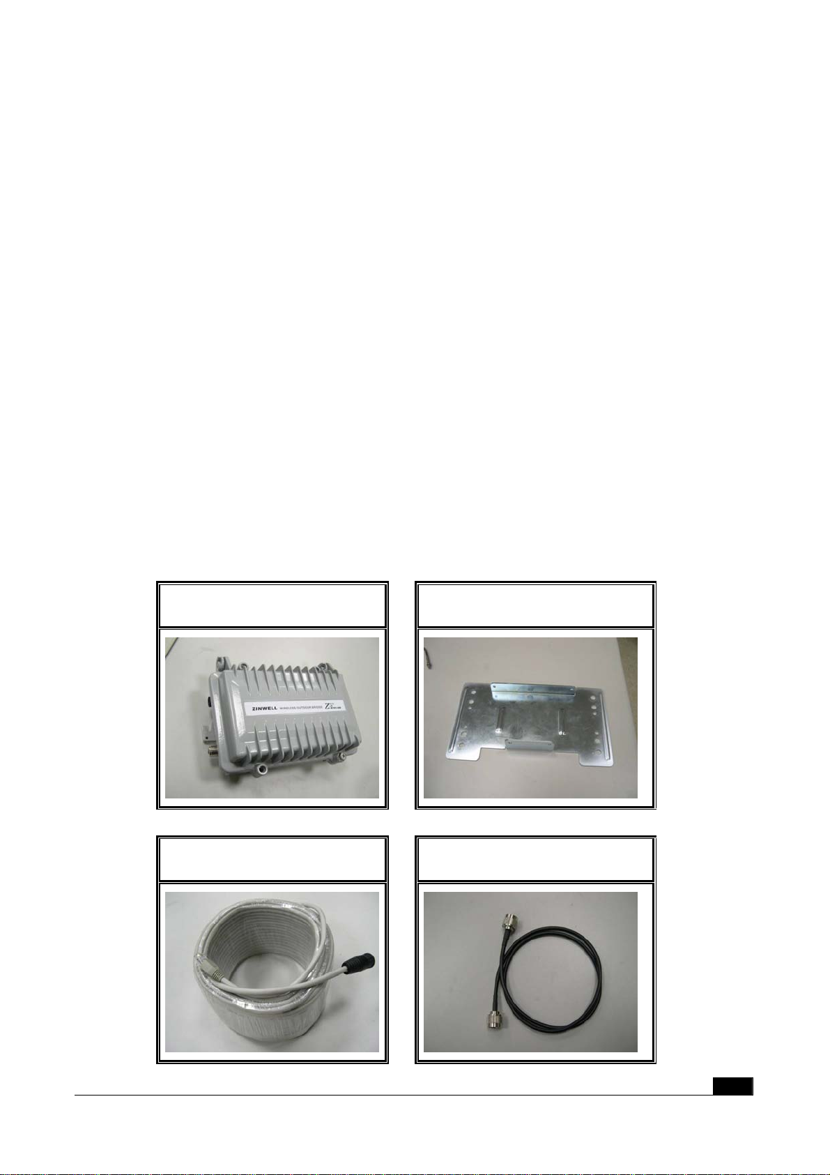
2.1 PACKING LIST ................................................................................................................................................5
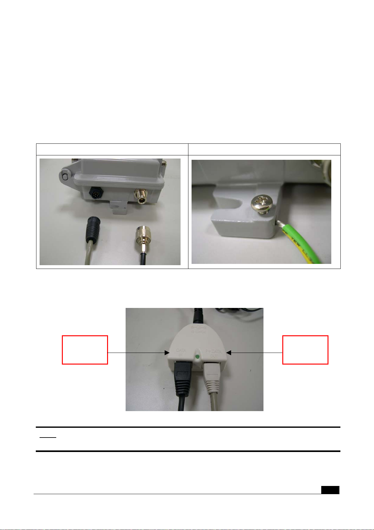
2.2 HARDWARE INSTALLATION ............................................................................................................................6
3SOFTWARE CONFIGURATION........................................................................................................................10
3.1 ENTER WEB CONFIGURATION PAGE...............................................................................................................10
3.2 STATUS OF WLAN OUTDOOR BRIDGE.........................................................................................................10
3.3 WIRELESS LAN SETTING.............................................................................................................................12
3.3.1 Basic settings..........................................................................................................................................12
3.3.2 Wireless Advanced Settings ....................................................................................................................15
3.3.3 Wireless Security setup...........................................................................................................................17
3.3.3.1 WEP Encryption Setting ....................................................................................................................17
3.3.3.2 WEP Encryption with 802.1x Setting.................................................................................................19
3.3.3.3 WPA Encryption Setting.....................................................................................................................20
3.3.4 Wireless Access Control .........................................................................................................................21
3.3.5 Wireless Site Survey................................................................................................................................23
3.3.6 WDS Settings..........................................................................................................................................24
3.4 LAN INTERFACE SETUP...............................................................................................................................26
3.4.1 Using the Fixed IP..................................................................................................................................26
3.4.2 Using DHCP Client................................................................................................................................28
3.4.3 Enable DHCP Server .............................................................................................................................29
3.5 WLAN AP STATISTICS ................................................................................................................................30
3.6 UPGRADE FIRMWARE...................................................................................................................................31
3.7 SAVE/RELOAD SETTINGS .............................................................................................................................31
3.8 SETUP PASSWORD ........................................................................................................................................32
4WIRELESS CONNECTION ARCHITECTURE.................................................................................................34
4.1 INFRASTRUCTURE MODE..............................................................................................................................34
4.2 AD-HOC MODE.............................................................................................................................................34
4.3 WIRELESS AP FUNCTIONS ...........................................................................................................................35
4.3.1 Access Point Mode .................................................................................................................................35
4.3.2 Access Point Client Mode (Ad-Hoc).......................................................................................................36
4.3.3 Access Point Client Mode (Infrastructure).............................................................................................36
4.3.4 Wireless Repeater...................................................................................................................................37
4.3.5 WDS (Wireless Distribution System) ......................................................................................................37
4.3.6 Wireless Bridge.......................................................................................................................................38
4.4 SELECTING AN APPROPRIATE SITE ................................................................................................................39
4.5 POWER OVER ETHERNET..............................................................................................................................39

4
1 Introduction
ZINWELL ZPlus-B191-OD Wireless Outdoor Bridge Unit (herein after referred as ODU) is
fully complying with 802.11b standard, featuring with easy-to-install, easy-to-manage, and
point-to-point and point-to-multipoint connection.
Our ODU is a flexible and cost-effective product which allows you to connect LANs located
in fart buildings with data transmitting rate up to 11Mbps. Our ODU is an ideal device that let
you can replace the expensive lease lines, such as T1 line or fiber optics.
With Power over Ethernet function, our ODU reduces installation expenses and increases
location options by using a single Ethernet cable to supply both data and power to our ODU.
ODU applications
Point-to-Point / Point-to-Multipoint Architecture
Indoor/Outdoor Architecture
Easy Installation
Features
Complied With IEEE 802.11b 2.4GHz Standard
Excellent Range with Build-in Power Amplifier and superior sensitivity receiver
Data Security with WEP, WPA-PSK, TKIP

2 Hardware Installation
This Chapter helps you to install the hardware in a quick and easy way.
2.1 Packing List
Before you start to install the ODU, make sure the package should contain the following
items:
Wireless Outdoor Bridge unit * 1
Mounting Kit * 1
Waterproof (IP67) RJ-45 Cable (30M) * 1
Waterproof (IP66) RF Cable (1M) * 1
Power Over Ethernet Kit * 1
Ground Wire * 1
2.5” /4” U bolts * 2 and Anchor * 4
6 dBi omni directional antenna * 1 (separated package)
RJ-45 Cable (1.5M) * 1
ODU Mounting Kit
Waterproof RJ-45 Cable Waterproof RF Cable
5

Power Over Ethernet Kit Ground Wire
RJ-45 Cable 6 dBi omni directional
antenna
2.5” /4” U bolt and Anchor
2.2 Hardware Installation
Once you check off everything from the package, you can start to install the ODU. You can
mount to a pipe, a pole or to the side of a building. The steps are showed in the
following:
1. You must mount the ODU into the bracket first.
Note: ALL the 4 screws had been tightened onto the ODU and bracket
6

2. You can use the 2” inch or 4” inch U bolt to mount on the pipe, depending on the radius
of the pipe. (Wall mounting is referred to Wall Mounting Figure) The two U bolts must
be mounted tightly. Be aware of not over-tighten the U bolt.
Pipe Mounting Figure
7

Wall Mounting Figure
3. After checking the ODU is mounted well, you can connect the following two cables: the
Waterproof RJ-45 network cable to “P+ DATA OUT” port of ODU and the RF cable to
antenna port. Additional waterproof tool, such as waterproof tape, is recommended
to use to enhance the waterproof function. It is suggested to have a lightening
protector between antenna and antenna port. Connecting the ground wire as the
figure of “ODU ground wire connection.”
ZPlus-B191-OD Cable connection ZPlus-B191-OD ground wire connection
4. Plug the other end of the waterproof RJ-45 cable to the PoE device. The PoE device
is guaranteed only in indoor environment.
Note: DON’T plug the power cord into PoE device to power on the system before
you finish install the antenna and Ground wire to ensure the safety.
DATA
IN
P+DATA
OUT
In the ODU indoor part installation, if the RJ-45 cable’s length is not long enough for you to
8

link to your network device, you can extend the cable length. However, make sure the
maximum length of the RJ-45 cable is 100M (about 109 yards) for normal operation under
802.3 standard.
When you plug the regular RJ-45 cable into the PoE device, you should use the regular
RJ-45 cable to plug into the “DATA IN” of “Power Over Ethernet Kit” to connect to
hub/switch or use the crosslink Rj-45 cable (Not included in the Packing List) to connect
with user’s PC.
The waterproof RJ-45 cable must be connected to the “P+DATA OUT” port.
Note: Be careful! Don’t plug the two cables inversely. It will damage the
devices!
Refer to the following figure for the complete system connection.
9
Power injector
ZPlus-B191-OD
Waterproof RF cable
RJ-45 cable
Waterproof RJ-45 cable
Power cord
Indoor
Outdoor
Power supply
HUB / SWITCH
Antenna
Ground wire

10
3 Software Configuration
3.1 Enter web configuration page
The default IPAddress for ODU is 192.168.2.254; the default IP address for Subnet Mask is
255.255.255.0.
You need to configure your PC’s TCP/IP setting before access the ODU.
For example:
• IP address 192.168.2.X (X means any figure from 1 to 253 and is not used by other device)
• Subnet Mask 255.255.255.0 (same as the ODU)
After you had configured your PC’s TCP/IP setting, you may need to reboot your PC to finish
the network configuration, if your OS in your PC asks you to do that such as Win98.
Now, you open a web browser and then enter the IP address of the ODU:
http://192.168.2.254
Then, you can enter the ODU’s web configuration page t0 configure ODU to meet
your requirements.
3.2 Status of WLAN Outdoor Bridge
The definitation of each terminology on status page:.
The ODU status description:
System
Alias Name Show this ODU device name.
Uptime System in operation time.
Firmware Version Show ODU firmware version
Wireless Configuration
Mode Show the mode (AP or Client) using
SSID Show the SSID setting name
Channel Number Wireless channel using in this ODU.
Encryption Encryption status
Associated Clients How many client connection now
BSSID Show the BSSID setting name now.
TCP/IP Configuration
Attain IP Protocol The IP setting mode
IP Address 192.168.2.254

Subnet Mask 255.255.255.0
Default Gateway 192.168.2.254
MAC Address 00:05:9e:80:01:a9
11

3.3 Wireless LAN Setting
3.3.1 Basic settings
1. “Alias name”: let you can set this ODU’s name to distinguish this ODU from others.
2. “Disable Wireless LAN Interface”: By clicking this function, ODU will not transmit RF
signal out. ODU will not connect to any Wireless LAN device.
3. Mode: ODU can support AP and Client modes; choosing the “AP” mode will make ODU
function as Access Point; choosing “Client” mode make ODU perform as a standard
wireless client.
Note :When ODU is under the client mode, ODU can only be connected by cross
link RJ-45.
4. Network Type: When you choose the “Client” mode, you can have two Network Types to
connect the WLAN, one is infrastructure mode and another is ad-hoc mode (You can get
more detail steps in Site Survey chapter.)
5. You can set the SSID name to let the other WLAN devices to locate this ODU.
6. The channel range is from 1 to 14 and auto function. You can manually choose the
channel to fit your WLAN environment, or you can just choose the auto function to detect
12

the best channel that every time the ODU power on at your installation site.
7. In the “Associated Client,” you also can click the “Show Active Client” to see which client
had connected to this ODU.
While using the Client mode of the ODU, you must be connected by a wired RJ-45 cable and can’t
use the AP mode’s functions.
13

This table shows the status of all clients who are connected to this ODU.
Each time you successfully changed the default setting, the page will show a “successful”
message.
14

3.3.2 Wireless Advanced Settings
The default setting is optimized for the normal operation. For specific application, setting
configuration will required highly attention to reach optimistic condition.
Note :
Any unreasonable value change to default setting will reduce the throughput of the ODU.
1. Authentication Type:Choose the Open system, Shared Key, or Auto type. The
default setting is “Auto.”
2. Fragment Threshold:While transmitting large files, this function will help you to
improve the network performance. (The default setting is disabled set the value to the
maximum)
15

16
3. RTS Threshold:This function is designed to prevent the low throughput from the
hidden node of WLAN device. The default setting is disabled (set the value to the
maximum).
4. Beacon Interval:The interval time to send the beacon. The default value is 100ms.
5. Broadcast SSID:Broadcasting the SSID will let your client find the ODU automatically.
If you disable the function, you must connect the xx by manually write down the ODU’s
SSID in your client setting.
6. Int. Roaming:This function will let users roam among ODUs. Users can have more
wireless working range. You should comply with the following instruction to ensure
that you can roam among the wireless coverage areas.
All the ODUs must be in the same subnet network and the SSID must be the
same.
If you use the 802.1x authentication, you need to have the user profile in these
ODUs for the roaming station.
Tx Power:The output power you can adjust to follow different country regulations.
Output Power Antenna gain
FCC Certification 200mW (default ) 6 dBi or 9 dBi
CE Certification 100mW (with
Antenna) 6 dBi or 9 dBi

3.3.3 Wireless Security setup
The default security setting of the encryption function is disabled. Choose your preferred
security setting depending on what security function you need.
17
3.3.3.1 WEP Encryption Setting
When use the WEP encryption, you can choose to set the WEP key or to use the 802.1x
Authentication.

If you decide to use the WEP encryption to secure your WLAN, refer to the following
setting of the WEP encryption:
1. 64-bit WEP Encryption:64-bit WEP key are the same with the encryption method of
40-bit WEP. You can input 10 hexadecimal digits {0~9},{a~f},{A~F}
2. 128-bit WEP Encryption:128-bit WEP key are the same with the encryption method
of 104-bit WEP. You can input 26 hexadecimal digits {0~9},{a~f},{A~F}
3. The Default Tx Key field will let you specify which of four keys you would want to use
in your WLAN environment.
18

3.3.3.2 WEP Encryption with 802.1x Setting
If you use the WEP encryption, you can also use the RADIUS server to check the
admission of the users.
Then you can choose WEP 64 or 128 bit encryption to fit in with your network environment.
The default Port is 1812. In IP address field, you need to specify the RADIUS server’s IP
address. The Password’s length is depending on your choice of WEP key’s bits.
19
Other manuals for ZPlus-B191-OD
1
Table of contents
Other Zinwell Network Hardware manuals