Zip HydroTap CS 75 User manual

804052US v1.27 06.21 CS75 Install Instructions Page 1 of 28
CS 75
Zip HydroTap
Installation and Operating Instructions
®
Scan QR Code to download the latest version of this document.
English French

Page 2 of 28 804052US v1.27 06.21 CS75 Install Instructions
Faucet Options
The HydroTap appliance series offers a range of interchangeable faucets to suit the customer’s needs. For
ease of installation, it is recommended to fit the faucet before installing the Command Center.
The installation procedure for each of the faucets is detailed in the Faucet Installation instruction book
supplied with the faucet.
For all operational features of the HydroTap, please refer to the User Guide.
Classic Arc Cube Wave
Faucet options

804052US v1.27 06.21 CS75 Install Instructions Page 3 of 28
HydroTap Specifications
Installation Check List .................................................................................................................. 4
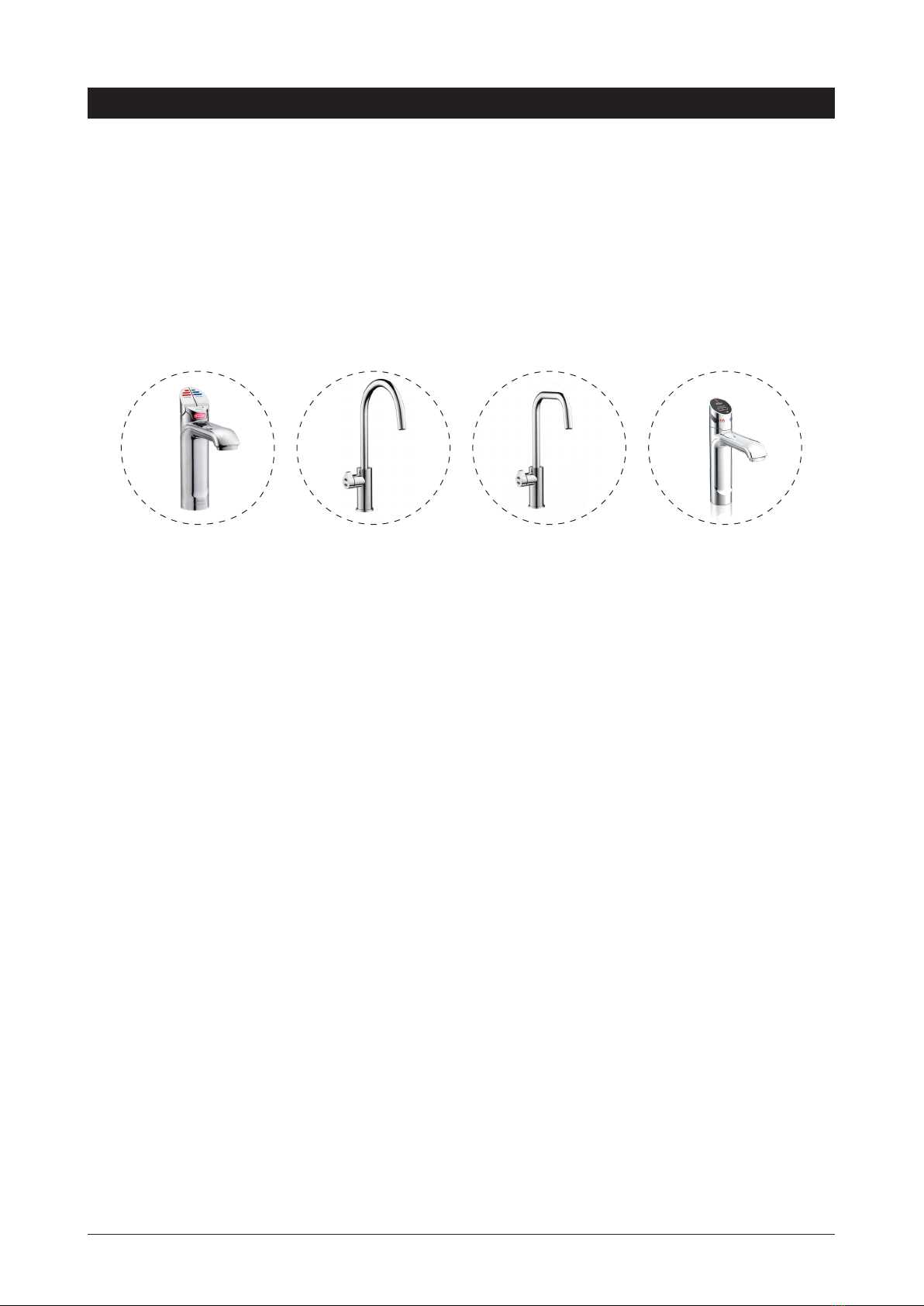
General Product Features............................................................................................................ 5
Important Safety Instructions ....................................................................................................... 6
Warnings and Regulatory Information.......................................................................................... 7
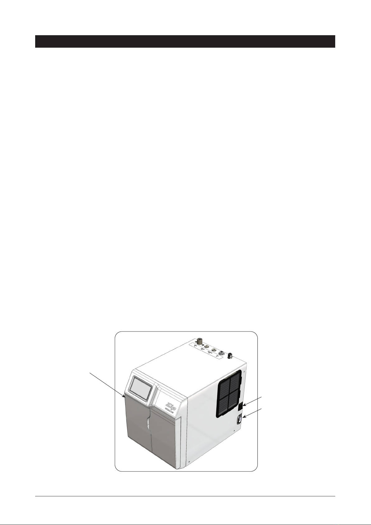
Major Components and Accessories ........................................................................................... 8
Technical Specification ................................................................................................................ 9
Before Installation and Site Requirements................................................................................... 10
Installation Procedure
STEP 1 - Measure and cut all the faucet holes before fitting the faucets
Section 1 - See Faucet Installation instructions (supplied with the faucet)
STEP 2 - Check for adequate ventilation
Section 2 - Ventilation
2.1 - Ventilation for All Models .......................................................................................... 11
2.2 - Cabinet Air Circulation .............................................................................................. 12
STEP 3 - Fit the CO2Gas cylinder
Section 3 - CO2Cylinder and regulator
3.1 - Secure the cylinder mounting ................................................................................... 14
3.2 - Connect the regulator ............................................................................................... 14
3.3 - Connect the gas hose............................................................................................... 14
STEP 4 - Install the Command Center
Section 4 - Command Center installation
4.1 - Electrical power supply ............................................................................................. 15
4.2 - Hose and tube fittings ............................................................................................... 15
4.3 - Test for gas leaks...................................................................................................... 16
4.4 - Installing carbonation valve....................................................................................... 17
4.5 - Model CS installation and connection....................................................................... 17
STEP 5 - Commission the HydroTap
Section 5 - Commissioning
5.1 - Select the language .................................................................................................. 18
5.2 - CO Purge.................................................................................................................. 18
5.3 - Filter Flush ................................................................................................................ 18
5.4 - Conditioning Procedure ............................................................................................ 19
5.5 - Carbonation Valve Flow Adjustment......................................................................... 19
5.6 - Backflow Prevention ................................................................................................. 20
Troubleshooting ........................................................................................................................... 21
End of life disposal....................................................................................................................... 21
Performance Data Sheets............................................................................................................ 22
Warranty....................................................................................................................................... 26
Index

Page 4 of 28 804052US v1.27 06.21 CS75 Install Instructions
Before Installation:
A. Read the instructions and check that there is adequate space to mount all of the components.
B. Note: Not all fittings are supplied with the appliance kit. Isolation valves and special tools are
not supplied (see Technical Specifications for details).
C. Check the mains water pressure is between 150 - 700 kPa (22 - 100 psi) and 200 - 700 kPa
(30 - 100) psi when a booster is installed.
D. Products are rated for either 110-120V, 60Hz OR 230V, 50Hz AC installations. Check that the
electrical power supply is suitable for your HydroTap.
E. Check the water quality to determine if extra filtration will be required. Note: This product
must be fitted to a potable water supply.
F. Check the appliance rating plate and ensure correct power is available for the appliance.
G. Check the under counter cabinet supporting the appliance is adequate for the total weight of
the appliance, when full of water.
Before Commissioning:
1. Check the Command Center has been installed correctly.
2. Flush the supply line before connecting to the Command Center.
3. Check all plumbing fittings have been tightened.
4. Ensure the outlet and vent pipes are positioned to drain correctly.
5. Ensure there is adequate ventilation.
6. Check all tubes from the Command Center to the faucet have a constant rise and there are no
sags or kinks in the hoses.
7. Check all electrical connections are correct and there are no loose wires.
Commission: (See Section 5)
8. Turn on the gas and water and check for leaks.
9. Turn on the power.
10. Purge the CO2.
11. Flush the filter.
12. Where applicable, programme the Command Center to suit the customer’s requirements.
Installation checklist

804052US v1.27 06.21 CS75 Install Instructions Page 5 of 28
Thank you for purchasing a Zip HydroTap. Please read and follow these instructions carefully to ensure safe
and trouble free service.
What is the Zip HydroTap ?
The Zip HydroTaps are electronically controlled, filtered, Boiling, Chilled and Sparkling water, drinking
systems for kitchens and tea rooms. The HydroTap Command Centers are under bench drinking water
appliances with a dispensing faucet mounted on a sink or bench, which may be used for residential or
commercial applications. The CS75 HydroTap utilises a conventional refrigerant compressor to chill the water
and a CO2gas cylinder to carbonate the chilled water. Chilled water dispensed is factory set to 6 - 10 °C (43-
50°F). These units are NOT designed to be used for sanitary fixtures.
The CO2bottle and the water filter require periodic replacement and are covered by a limited OEM warranty.
It is important that the Installation be done safely, correctly and completely, in order to utilise all the benefits
the HydroTap can provide. The Classic HydroTap can be ordered with the Faucet Head Assembly for
Accessible use. Accessible levers are supplied with Braille caps for the visually impaired.
Usage:
The Zip HydroTap is intended for use in residential household and similar applications such as: Rural and
urban residential Kitchens, Hotels, Motels, Bed and Breakfast and other residential type environments
General Product Features
HydroTap CS
Command Center
ON-OFF Switch
IEC Socket
110-120V, 60Hz
OR
230V, 50Hz

Page 6 of 28 804052US v1.27 06.21 CS75 Install Instructions
Important Safety Instructions
This manual contains important safety, Installation instructions for the Zip HydroTap.
Safety
This appliance is not intended for use by persons (including children) with reduced physical,
sensory or mental capabilities, or lack of experience and knowledge, unless they have been
given supervision or instruction concerning use of the appliance by a person responsible for
their safety. Children should be supervised to ensure that they do not play with the appliance.
For products sold in Europe, this appliance can be used by children aged from 8 years and above and
persons with reduced physical, sensory or mental capabilities or lack of experience and knowledge if they
have been given supervision or instruction concerning use of the appliance in a safe way and understand
the hazards involved. Children shall not play with the appliance. Cleaning and user maintenance shall not be
made by children without supervision.
Refrigerant
The Zip HydroTap Command Center contains R134A refrigerant under pressure. Maintenance of the
refrigeration unit must be carried out by an accredited service provider or qualified refrigeration technician.
Qualifications
If the power cable is damaged it must be repaired only by a qualified technician. To avoid hazards, all
Installation procedures must be carried out by a suitably qualified tradesperson. The power cable and power
outlet must be in a safe visible position for connection.
Venting
Ensure the faucet body is located so the faucet outlet safely dispenses into the sink bowl area.
Lifting
Take care when lifting the Zip HydroTap Command Center. Some units may exceed safe lifting limits. If you
feel this is beyond your personal capabilities, please seek assistance with the lift. The weights of the units are
marked on the packaging. Do not lift the Command Center by the front cover or any connections at the top
rear of the unit. Refer to the technical specifications for the weight of your product.
Airflow
The ambient operating temperatures, when installed in a cabinet, must be between 5 - 35°C (41 - 95ºF). The
system will operate satisfactorily only with proper air ventilation. The recommended air gaps of 50mm (2”) on
each side, and 200mm (8”) above must be provided. See section 2 for correct ventilation details.
Positioning
It is important to ensure the Command Center is positioned in an accessible area close to the floor level. The
Command Center must have its base mounted in a horizontal position with all inlets and outlets facing up.
The Faucet must be located above the Command Center. See Section 4 for details.
!

804052US v1.27 06.21 CS75 Install Instructions Page 7 of 28
Important Safety Instructions
WARNINGS
1. The Zip HydroTap Command Center must be earthed. The resistance of the
earth connection from each exposed metal part must be less than 1 ohm.
2. All Installation and service work must be completed by trained and suitably
qualified Tradespeople. Faulty operation due to unqualified persons working
on this product, or any other Zip product may void warranty coverage.
3. All Plumbing and Electrical connections must comply with local, state and
federal codes.
4. All Plumbing and Electrical connections must be made in accordance with
local regulations.
5. Ensure the electrical power supply at the installation site is suitable for
your HydroTap. HydroTap models are rated for either 110-120V, 60Hz, OR
230V, 50Hz AC installations.
6. Command Centers must never be located near, or cleaned with water jets.
7. Zip HydroTaps are not to be exposed to the elements of nature
8. Due to the process of continuous improvement, Zip reserves the right to
change details mentioned in this manual, without notice.
9. If this device is not maintained and operated as specified in this document,
there is a risk of exposure to contaminants.
!
CO2Cylinder Warnings:
•
Pressurised container.
•
Protect from sunlight.
•
Contains gas under pressure, may explode if heated.
•
Do not expose to temperatures exceeding 50°C (122°F).
•
Do not pierce or burn, even after use.
•
Do not refill – non rechargeable
•
Ensure cylinder is empty before disposal.
•
Do not expose to naked flame or any incandescent material.
•
Keep out of reach of children.
•
High concentration of gas may cause asphyxiation.
•
Use only in ventilated areas.
•
Store in a location with a volume no less than 50 cubic meters for each 6 lb
bottle.
•
Use only in an upright position.
•
This bottle must be used with the approved pressure regulator.
•
Avoid shock.
•
Use according to MSDS (Material Safety Data Sheet).

Page 8 of 28 804052US v1.27 06.21 CS75 Install Instructions
Parts supplied Description
1x 4
HydroTaps
with hoses
(Classic faucet
shown)
1x
HydroTap
Command Center
with air and water
filters
1x
Mains water
connection hose
Vent Kit
1x Inlet vent
1x Outlet vent
9 x Screws
1x Installation
Instructions
(this book) and
1x User Guide
1x
CO2gas cylinder &
regulator assy.
Major components and accessories
Accessories Description
Font (Drip Tray)
Kit for Arc & Cube
models
93580US (Chrome)
Font (Drip Tray) Kit
for Classic Models
93303US (Chrome)
Replacement Filter
1Z-LS
(Culligan P/N:
01034276)
Accessibility Lever
Kit
Install
Instruct
User
Guide

804052US v1.27 06.21 CS75 Install Instructions Page 9 of 28
Technical Specifications
Models*: CS75 (230V) - Classic XX
CS75 (230V) - ARC XX
CS75 (230V) - CUBE XX
CS75 (230V) - Wave XX
CS75 (110-120V) - Classic XX
CS75 (110-120V) - ARC XX
CS75 (110-120V) - CUBE XX
CS75 (110-120V) - Wave XX
Chilled and Sparkling models CS75 (230V) CS75 (110-120V)
Command Center dimensions, W x D x H,
mm (in)
280 x 406 x 333
(11.0” x 16” x 13.0”)
280 x 406 x 333
(11.0” x 16” x 13.0”)
Dry weight, kg (lb)**** 24 kg (53 lb) 24 kg (53 lb)
Water inlet connection 1/2” BSP 1/2” BSP
Power outlets required 1x NEMA6-15:
230V, 50/60Hz, 15A
1x NEMA5-15: 120V,
50/60Hz, 15A
Power rating 1.5A (175W)
at 220-240V, 50/60Hz
2.43A (225W)
at 110-120V, 50/60Hz
Refrigerant R134a R134a
NOTES:
Do not use with water that is microbiologically unsafe or of unknown quality without adequate disinfection
before or after the system. Systems certified for cyst reduction may be used on disinfected waters that
contain filterable cysts.
* Available in a range of premium metallic finishes. XX refers to the specific finish of the faucet.
** CS75 – Classic XX, CS75 – ARC XX and CS75 – CUBE XX have been tested and certified by WQA against
NSF/ANSI Standard 372 for low lead requirement, and against NSF/ANSI Standard 42 and NSF/ANSI Stand-
ard 53. This will deliver the required bacteriostatic effect and the reduction of aesthetic chlorine, taste, odor,
nominal particulate Class I (≥ 0.5 µm to < 1 µm), cyst and lead as verified and substantiated by test data. See
Performance Data Sheets for specific performance claims. Certified performance claims are only valid when
filter cartridge 1Z-LS (Culligan Part Number 01034276) is used.
*** CS75 - Classic XX, CS75 – ARC XX, CS75 - CUBE XX, and CS75 - Wave XX have been certified by
IAPMO R&T against NSF/ANSI Standard 372 for low lead requirement, NSF/ANSI Standard 42, NSF/ANSI
Standard 53, CSA B483.1, and ASSE 1087. This will deliver the required bacteriostatic effect and the reduc-
tion of aesthetic chlorine, taste, odor, nominal particulate Class I (≥ 0.5 μm to < 1 μm), cyst and lead as veri-
fied and substantiated by test data. See Performance Data Sheets for specific performance claims. Certified
performance claims are only valid when filter cartridge 1Z-LS (Culligan Part Number 01034276) is used.
**** Add an extra 5 kg (11 lb) when full of water.
*****

Page 10 of 28 804052US v1.27 06.21 CS75 Install Instructions
Before Installation
Before installing ensure that the following have been provided at the Installation site:
•
Review all the technical specifications.
•
Ensure the undersink can support the product weight - allow an extra 5kg (11lb) when full.
•
Sufficient space in the cabinet to install all of the Command Centers in accordance with these
Installation Instructions. Refer to technical specification for dimensions. Make allowance for a booster
heater and / or water softener if required.
•
Depending on your HydroTap model, either a 110-120V, 60Hz OR a 230V, 50Hz 15A AC electrical
power outlet will be required.
•
A potable water supply connection with isolating valve inside the cabinet within reach of the braided
hoses and positioned so that the connection point and the stop cock will not be obstructed when the
Command Centers are installed.
•
A cold water supply with a working pressure range of 250 - 700 kPa (37 - 100 psi) connected via an
isolation valve. Water inlet connection size is 1/2” BSP. The system shall only be supplied with cold
water.
•
Potable water should have a minimum TDS (Total Dissolved Solids) of 50 ppm. In areas where the
TDS exceeds 150 ppm and where mineral scale could be a problem, consideration should be given to
the maintenance required. Adding a water softener or reverse osmosis system should be considered.
•
The appliance must be placed with its base in a horizontal position.
Note: Check all cable and hose lengths against inlet /outlet positions before proceeding (See Section
4 for general layout).
IMPORTANT! Do not proceed with installation if these requirements are not met.
!
Section 1
Faucet Installation
Refer to the Faucet installation instruction book.

804052US v1.27 06.21 CS75 Install Instructions Page 11 of 28
Clearance
405
Air Space
Min 200mm (8”)
3mm (0.15”) buffer to
ensure ventilation gap
Section 2
Ventilation
2.2 Recommended Installation Diagram
When installing air ow ducts, the following tools will be required:
•
Jigsaw and a 12mm (½”) Drill
•
Keyhole or Wall Board saw.
2.1 Ventilation for All Models
Proper air circulation must be provided for all models. The system will operate correctly only if the
recommended air gaps are achieved during installation.
IMPORTANT: Allow a minimum clearance envelope of 50mm (2”) either side, and 200mm (8”)
above the Command Center.
Fit the 3mm (0.15”) door buffer to the inside edge of the cabinet door to allow sufficient air circulation inside the
cabinet (see diagram below).
!

Page 12 of 28 804052US v1.27 06.21 CS75 Install Instructions
Ventilation
Air inlet vent position
Airflow through the cabinet
B
D
Cool air IN
Warm air
OUT
Door outlet vent
If the air flow, using the silicone door buffers, is insufficient, it will be necessary to fit a standard HydroTap
vent kit, which ensures heat dissipation through natural convection via installed vents.
For high use applications, where the cabinet space temperature is near 35°C (95°F) or higher, the inlet vent
(See Item B below) and silicone buffers, need to be fitted. If the airflow is still insufficient to maintain normal
operating temperatures then the inlet vent and door outlet vent (See item D below) will need to be fitted.
Note: The vent kit has to be installed in a way that allows air to be drawn in from the bottom of the cabinet
and expelled through the top of the cabinet. Therefore placement of the outlet vent should be towards the top
of the door or on the side of the cabinet.
2.3 Alternative Ventilation
1. Drill four pilot holes
12mm (½") dia.
2. Finish the cut-out using
a jig saw and keyhole
or Wall Board saw
Cut-out details
(½")
(11¼")
(2⅜")

804052US v1.27 06.21 CS75 Install Instructions Page 13 of 28
Typical Cut-out procedure for
Ventilation
1. Mark out and cut the air inlet and door outlet holes as shown
2. Ensure the air inlet vent and air outlet vent are positioned at opposite ends
of the same cabinet space.
3. Fit the inlet vent, as shown and secure with 5 screws
4. If required, fit the outlet vent, as shown in the hottest part (top) of the
cabinet and secure with 4 screws
BD
(1/5")
Cut-out details
(12⅜")
(½")
(½")
(½")
(11/16")

Page 14 of 28 804052US v1.27 06.21 CS75 Install Instructions
Section 3
CO2Cylinder
WARNING:
CO2gas cylinders must be installed in an open plan area or in an
enclosed room, with a volume no less than 50 cubic metres (65
cubic yards) for each 2.6kg (6lb) of stored gas. If more than 1 gas
cylinder containing CO2is present within the same location, the
recommended ventilated area should be in proportion to the number
of gas cylinders stored in that location.
A ventilated area is a non-enclosed area which could include the
kitchen, living room etc.
See gas bottle and MSDS sheet for a complete list of warnings.
5.1 Secure the cylinder mounting
Secure the gas bottle supplied to a suitable wall, within 3 ft of the
Command Center, in an upright position. This is done by screwing
the metal plate holding the hook-and-loop strap to a cabinet wall,
200mm (8”) above the floor or base of the cabinet. Make sure the
gas bottle can stand before securing to the wall.
Due to regulatory requirements the gas bottle must be stored
securely and in an upright position.
3.2 Connect the regulator
Make sure the regulator knob is turned fully clockwise to the end-
stop before fitting see fig.1. Fit the regulator to the gas bottle. Be
aware that some CO2may be discharged from the connection to the
regulator as the bottle and the regulator are be assembled together.
Any CO2released will be cold. Continue to screw on the regulator to
stop this leakage.
Note: The regulator comes pre-set fixed pressure at 300 kPa (44 psi).
3.3 Connect the gas hose
Connect the braided gas hose to the top of the Command Center
via the John Guest fitting marked ‘CO2 IN’ Then connect the
threaded end to the regulator, taking care not to lose the plastic
olive located inside the threaded nut. To turn the gas ON, rotate the
regulator knob anti-clockwise to the end-stop.
!
OPEN
Turn the knob fully clockwise
before fitting the regulator
Rotate the knob fully anti-
clockwise to turn the gas on.
CLOSED

804052US v1.27 06.21 CS75 Install Instructions Page 15 of 28
Section 4
Command Center Installation
4.2 Hose and tube fitting
•
Remove all caps from the top of the Command Center
•
Fit the foam insulation to the Blue and to the White tubes after trimming them to length
•
Install the mains water braided hoses to the Command Center before locating the unit in place.
NOTE: Do not overtighten
NOTE: Before installation, determine whether a water softener or an external filter is required.
4.1 Electrical power supply
Warning: HydroTap models are available for either 110-120V, 60Hz OR 230V, 50Hz AC
installations. Ensure the electrical power supply at the installation site is suitable for your HydroTap.
Use only the power lead supplied with the product. Connect the power lead to the HydroTap and
connect the plug into the electrical power outlet, ensuring both ends are securely engaged to reduce the risk
of overheating.
John Guest fittings (Insertion and removal)
Be careful when cutting the poly tube so that there are no rough
edges and that the tube is not distorted.
1. Use a sharp knife to ensure the tube has a clean, straight
edge. Do not cut at an angle.
2. Remove any swarf or unwanted material.
3. Push the tube into the John Guest fitting making sure all
connections to the John Guest fittings are pushed in past
the “O” ring to full depth, at least 15mm (⅝”).
4. Check for a good joint by pulling back on the tube. If the
tube comes out, of the fitting, repeat the above step.
5. To remove the tube, press the collet into the fitting and at
the same time pull back on the tube.
Power lead for 110-120V, 60Hz ONLY
(NEMA 5-15 / IEC C19)
Power lead for 230V, 50Hz ONLY
(NEMA 6-15 / IEC C13)

Page 16 of 28 804052US v1.27 06.21 CS75 Install Instructions
Installation Instructions
4.3 Test for gas leaks:
Using soapy water perform a leak test. Turn the gas OFF.
Apply the soapy water to the gas connections using a sponge
or brush. Cover all of the gas joints with a liberal amount of
suds.
Turn ON the gas. Inspect the joint for leaks. If any bubbles
appear and grow, there is a gas leak at the connection. The
joint will need to be resealed and tested again. Clean away the
soapy residue and tighten or refit the leaking connection. Make
sure the regulator is turned off when tightening or refitting the
leaking connection.
Refit the gas bottle to the hook-and-loop strap and secure the
bottle in an upright position.
NOTE: Care must be taken when working with high
pressure carbon dioxide.
IMPORTANT:
After replacing a bottle or after making a gas connection,
check for gas leaks between regulator and bottle, and be-
tween regulator and braided hose.
Test for leaks at these two points
4.4 Installing carbonation valve
1. Connect the white tube for sparkling water from the faucet
to the outlet of the carbonation valve.
2. Connect the white tube from the inlet of the carbonation
valve to the Sparkling Outlet connection on top of the Com-
mand Center, as shown in Section 4.3.
3. See section 5.4 for carbonation valve ow rate adjustment.
To faucet
From Sparkling Outlet
of Command Centre

804052US v1.27 06.21 CS75 Install Instructions Page 17 of 28
Installation Instructions
4.5 Model: CS75 Chilled Sparkling
Note:
Mains hose length is
750mm (30”)
Plug and Cord length is
1800mm (70”)
Position the Command
Center close to the
outlet faucet, within
reach of the hose and
cord lengths supplied
Note:Note:
The hoses need to have
a constant downward
gradient to the
HydroTap to allow all
water to drain back into
the tanks.

Page 18 of 28 804052US v1.27 06.21 CS75 Install Instructions
Section 5
Commissioning
5.2 - CO2Purge
1. Press the [START] button to commence the purging
process.
2. Purge for 10 seconds and ensure all water has stopped
flowing through the faucet. You will hear the CO2gas
escaping from the faucet.
3. Press the [Stop] button.
4. Press [Next] for the filter flush screen
The HydroTap is now ready to be commissioned.
•
Turn ON the water and gas and check for any leaks.
•
Turn the power ON at the power outlet and at the side of the Command Center
•
Familiarise yourself with the operation of the Faucet, in preparation for use (See User Manual)
•
Follow the Installation instructions below (and review Section C of the User Manual).
•
Initially you will be prompted to select a language
•
After commissioning, the system may be customised by selecting further options in
Section G - Settings, within the User Manual.
5.1 - Select the Language
Initial Commissioning screen Language selection screen
5.3 - Filter Flush
A new filter cartridge is provided (but NOT fitted), inside the
filter door. Unpack the new filter cartridge and write today’s
date on the label. To install the cartridge, align the key tabs
and insert upwards into the filter head. Turn the cartridge to the
right until it locks in place.
Have a 10 liter (2.6 gallon) bucket or similar container (not
supplied) at the ready to hold a quantity of water that will be
ejected while the Filter Flush Mode is in operation. Open the
filter access door on the front of the HydroTap and the filter
cartridge will be exposed. Located to the rear RHS of the
cartridge is a flush line and the flush line stop cock. Place the
valve end of the flush line into the bucket or container.
1
1
2

804052US v1.27 06.21 CS75 Install Instructions Page 19 of 28
Commissioning
Note: You will need to Press the [Start] [Stop] buttons to start
and stop the filter flush.
NOTE: For any subsequent lter changes or any operational
procedures, please refer to the HydroTap user guide, located
inside the lter housing access door.
OPEN
CLOSED
Stop cock operation
1. Turn the flush line stop cock ON (See diagram).
2. Press [Start] and allow at least 10 liters (2.6 gallons) of
water to flush through the filter.
3. The product details will be displayed in the screen.
4. Once the filter flush is finished, Turn the stop cock OFF
then press [Stop] to end filter flush mode.
5.4 - Conditioning Procedure
Zip HydroTap Command Centers are sanitized during manufacturing and require ushing before normal use.
1. Turn off CO2gas at the regulator.
2. Dispense 10 liters (2.6 gallons) of chilled water from the chilled outlet of the HydroTap (equivalent to 4
complete tanks full of water.
3. If water bubbles or foams, repeat step 2 above.
4. Let lled tank stand for one hour at operating temperature.
5. After one hour, repeat step 2.
6. Dispense 2 liters (½ gallon) of sparkling water from the sparkling outlet. Repeat the 2 liters (½ gallon)
dispense until the water is clear.
7. Check that the water is clear, and that there are no bubbles or foam present in the dispensed water.
8. Turn on the CO2gas at the regulator. The HydroTap is ready for use.
5.5 - Carbonation Valve Flow Adjustment
1. After product commissioning and CO2purge, you are now ready
to adjust the carbonation ow rate.
2. To adjust the ow rate, rotate the adjustment screw anti-clock-
wise to increase the ow and clockwise to decrease the ow.
3. To measure the ow rate you have set, use a measuring cup
or jug and run the sparkling water for 15 seconds (the HydroTap
has a default 15 seconds dispense time, which will help in your
ow rate set up). Multiply the amount of water dispensed in that
15 seconds by 4 to get your ow rate in gallons per minute. 1.6
liters (0.4 gallons or 46 . oz) per minute is the optimum ow rate.
Important – If you adjust the ow rate too high, you will empty the
carbonation tank of water leaving only CO2to be dispensed from
the faucet. This will result in inconsistent ow (spluttering).
+
–
!
Warning - Take care NOT to
use excessive force during
adjustment of the valve.

Page 20 of 28 804052US v1.27 06.21 CS75 Install Instructions
Commissioning
All HydroTap models that have sparkling/carbonated water functionality include the following integral Backflow
Prevention.
Main Water Inlet
The Dual Check Valve (DCV) on the Mains
Water inlet connection is designed to ensure
a uniform direction of flow throughout the
HydroTap. This valve configuration eliminates
any possible contamination of the mains water
supply, caused by backflow or back siphonage
and is the is a secondary safety feature in the
case where the of the inlet safety solenoid.
The DCV also maintains a constant pressure
upstream of the inlet safety solenoid. There are
two (2) operating principles:
• Firstly, one check valve will still act, even if the other is jammed open;
• Secondly, the closure of one valve reduces the pressure differential across the other, allowing a more
reliable seal and avoiding the possibility of minor leakage.
The HydroTap MUST NOT be operated without the Dual Check Valves in place.
Internal Carbonator
There are two (2) Check Valves on the internal
Carbonator. The Check Valves ensure the flow
of CO2 gas and water is maintained in one
direction, into the carbonator. These valves help
to maintain the pressure needed to ensure the
gas remains dissolved in the water while inside
the carbonator. The Check Valves are designed to stop any backflow of gas and/or water out of the internal
carbonator.
In addition to the HydroTap’s integral Backflow prevention
Some authorities require additional Backflow Prevention to be installed to comply with the Local, State or
Federal plumbing code requirements. Both the Universal Plumbing Code (UPC) and National Standard
Plumbing Code (NSPC) require the use of an American Society of Sanitary Engineers (ASSE) 1022 backflow
preventer on the supply to carbonators under UPC 603.5.12 and NSPC 10.5.8.
UPC: “Potable water supply to beverage dispensers, carbonated beverage dispensers, or coffee machines
shall be protected by an air gap or a vented backflow preventer in accordance with ASSE 1022. For
carbonated beverage dispensers, piping material installed downstream of the backflow preventer shall not be
affected by carbon dioxide gas”.
NSPC: “The water supply to a carbonated beverage dispenser shall be protected against backflow with an
integral backflow preventer conforming to ASSE 1022 or an air gap. Carbonated beverage dispensers and
carbonated beverage dispensing systems without an integral backflow preventer conforming to ASSE 1022 or
an air gap shall have the water supply protected with double check valve and atmospheric vent conforming to
ASSE 1022.”
In order to comply with this requirement the Installer MUST install an ASSE 1022 approved backflow device
on the water supply leading to the HydroTap. This will ensure compliance with the requirement to protect the
potable water supply to the carbonated beverage dispenser.
5.6 - Backow Prevention
!
Table of contents
Popular Water System manuals by other brands

evenes
evenes EASYFLOW 4I installation manual

Everpure
Everpure Kleensteam II Twin System EV9797-22 Specification sheet

Wayne
Wayne Jet Pump Water Systems Shallow Well Operating instructions and parts manual

Naked
Naked NKD1 Installation and setup guide

HYDRO GUARD
HYDRO GUARD LongNeck Standard HG-31 User's operation manual

PREMIER TECH
PREMIER TECH Rewatec NEO Installation and assembly guide