ZIPPY M1S2 series User manual

1.1 INTRODUCTION
First of all, thank you for purchasing M1S2 series redundant power supply for 1U.
The M1S2 is a 1+1 hot-swappable / hot-pluggable redundant power supply. It consists
of,
1) complete metal frame
2) compact size power module
3) backplane
The M1S2 series redundant power supply offer a maximum 400/500 watts of output
power. The power module is in compact size, and built-in a 40mm ball bearing DC fan
for better ventilation. Each power module is designed with 5 outputs (+3.3V, +5V,
+12V, -12V, and +5Vsb) circuits, and compliant to ATX12V. All you can see on the
backplane is just passive components and this is the key point for longer MTBF.
The M1S2 series offer a warning sub-system, including LED display, buzzer alarm,
TTL signal, It guides user the fast way to find out the power supply and DC fan status.
When all the power modules operate normally, it balances the load share through its
parallel design, which increases the reliability of power system.
To really discover the power system and ease in using it, we recommend you to read
through this manual carefully.

1.2 PACKING
Your M1S2 series should consist of the following,
a) M1S2 x 1
b) Accessory pack x 1
1.3 MODEL DESINGATION
Model number identification
X X Y Z X – X XXX X X X
1 2 3 4 5
6 7
8 9 10
1st --- Category
X --- blank AC input ( AC – DC )
D -48Vdc input
B -24Vdc input
2nd --- Serial ID
X --- R redundant 1 + 1
M redundant N + 1
3rd --- for # U use
Y --- 1 for 1U use
2 for 2U use
4th --- PM or Customer specify
5th --- # of power module in N+1 system
X --- 1 single
2 1+1 power system
3 2+1 power system
4 3+1 power system
6th --- # of the channel
X --- 2 5V, 12V ( Disk Array )
4 5V, 12V, -5V, -12V ( AT )

5 5V, 12V, 3.3V, 5Vsb, -12V ( ATX / EPS )
6 5V, 12V, 3.3V, 5Vsb, -5V, -12V ( ATX / EPS )
7th --- # of total wattages
XXX --- XXX W
AXX --- 10XX W
BXX --- 11XX W
CXX --- 12XX W
………
8th --- attribute
X --- P w/ PFC
F w/ EMI filter
V HIGH EFFICIENCY
9th --- Use FAN type
X --- 3 use 3.8CM type
4 use 4CM type
6 use 6CM type
8 use 8CM type
10th --- chassis type
X --- H horizontal type
V vertical type
M horizontal + vertical type

1.4 FEATURES
M1S2 series, 400W/500W + 400W/500W redundant power supply with active PFC,
complaint to ATX12V
All circuit designed into the power module
Hot-swap and hot-plug ability
Full range (90VAC – 264VAC) operation
Active Power Factor Correction (PFC) built-in
Balance load sharing design
Remote sensing design
Meet FCC, CISPR EMI regulation
Faulty free- slide rail design
Compact size for 1U chassis
Dual inlets design
Designed with one 40mm ball bearing DC fan on power module
1.5 DRAWING


1.6 SPECIFICATION
NPUT CHARACTERISTICS: M1S2-5400V4H / M1S2-5500V4H
A
、
INPUT CHARACTERISTICS
:
1
、
VOLTAGE
:
90
~
264VAC FULL RANGE
2
、
FREQUENCY
:
47
~
63HZ
3
、
INPUT CURRENT
:
3A / 4A
(
RMS
)
FOR HIGH RANGE INPUT VOLTAGE;
6A / 8A
(
RMS
)
FOR LOW RANGE INPUT VOLTAGE
4
、
INRUSH CURRENT
:
20A MAX. FOR 132 VAC PER MODULE
40A MAX. FOR 264 VAC PER MODULE
B
、
OUTPUT CHARACTERISTICS
:
OUTPUT OUTPUT CURRENT
REGULATION OUTPUT RIPPLE
&
VOLTAGE
MIN. MAX. LOAD
LINE NOISE MAX. [P-P]
+5V 1 25 ±5% ±1% 50mV
+12V 2 33/41 ±5% ±1% 120mV
-12V 0 0.8 ±10% ±1% 120mV
+3.3V 1 25 ±5% ±1% 50mV
+5VSB 0.1 3.5 ±5% ±1% 50mV
REMARK: 1. TOTAL MAX OUTPUT OF +5V AND +3.3V NOT EXCEED 170W.
2. POWER MODULE TOTAL OUTPUT POWER NOT EXCEED 400W/500W
C
、
SPECIFICATION
TEMPERATURE RANGE
:
OPERATING 0
℃
~
40
℃
,
STORAGE -20
℃
~
80
℃
HOLD UP TIME
:
16mS MIN. AT FULL LOAD & 115 VAC INPUT VOLTAGE
DIELECTRIC WITHSTAND
:
INPUT/OUTPUT 1500 VAC FOR 1 minute, INPUT TO
FRAME GROUND 1500 VAC FOR 1 MINUTE
EFFICIENCY
:
84% / 85% MAX.
POWER GOOD SIGNAL
:
ON DELAY 100mS TO 500mS
,
OFF DELAY 1ms
OVER POWER PROTECTION
:
110
~
150% MAX
OVER VOLTAGE PROTECTION
:
+5V→5.8V
~
6.9V
,
+3.3V→3.9V
~
4.6V
,
+12V→13.9V
~
16.4V
OVER CURRENT PROTECTION: +3.3V→27.5~37.5A, +5V→27.5~37.5A,
+12V→36.3~59.4A(400W) / +12V→45.1~67.5A(500W)
SHORT CIRCUIT: +12V, -12V, +3.3V, +5V, +5VSB
EMI : FCC CLASS A , CISPR 22 CLASS A
SAFETY
:
UL 60950-1, CSA 22.2 NO.60950-1-03 1ST Edition , TUV IEC60950-1,
CCC
FAULTY ALARM METHODS: LED, BUZZER, TTL SIGNAL

MEET IEC-1000-3-2 CLASS D (ACTIVE PFC)
HOT-SWAPPABLE/HOT PLUGGABLE REDUNDANCY FUNCTION
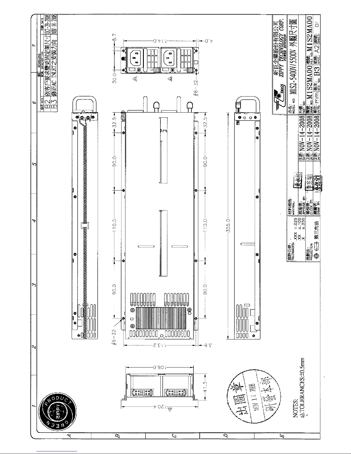
DIMENSION: 355(D) * 106(W) * 41.3 (H)mm
COOLING: ONE 40mm DC FANS (MODULE)
AC INLET IN EACH MODULE
1.7 INSTALLATION & TESTING
Mount the power supply into the system chassis by using proper mounting tool. The
mounting holes of the power supply should match up with those in the chassis.
Connect the power connectors to the M/B by following the M/B instruction. There is
various on connectors / pinouts in both power supply and M/B. Please ensure to
connect the matched one; otherwise, it will cause unexpected harms.
Connect the remaining power connectors to the various peripherals as needed. These
connectors are “keyed”, so there will be only one possible way to connect them.
Before applying power source to the system, make sure these is no loosed or
incorrect connectors. Double check if all connection to the M/B is matched properly.
Maybe you would like to test the redundancy function before you put back the cover of
your system chassis, then, please power it on. If the power system operates normally,
the individual LEDs on power module and the external warning LED light in GREEN.
Now, remove one power module from the power system, the warning buzzer in the
power system will sound, the external warning LED, which displays the status of the
total power system, will change to be RED, the individual LED indicating the power
module’s status will distinguish. Meanwhile, the power system will continue to backup
the power output without affecting the operation of your computing system.
The warming buzzer will sound continuously. You can reset warning buzzer by
pressing the buzzer reset switch. Insert the power module which is removed for test
earlier. The sound of the warning buzzer will stop; the external warning LED will turn
to be GREEN again; the LED indicating the status of power module will light in
GREEN. Test another power supply by performing the same procedure.
If everything works out fine, then turn off the power system. Now put back the cover of
the chassis and tighten with the screws which you have retained earlier. Now you
have completed the installation of M1S series redundant power supply.

1.8 Hot-swap procedures
Please refer to the following when either power module is defective.
1) Locate the defective power module by examining the individual LED (if LED is
distinguished, it indicates the power module is defective).
*** WARNING:
Please perform the following step carefully; otherwise, it may cause the whole system
shutdown.
*** WARNING:
Please do not remove the defective power module until you have worn gloves to keep
from been burned. This is due to the cover of the power module is used as heat sink
for cooling. Usually, its temperature is around 50-60 degree Celsius under full load
condition.
2) Loose the screws of power module bracket.
3) Plug out the defective power module.
*** WARNING:
Please put aside the power module to wait for cooling down. Keep other people from
toughing it until it is cooled.
4) Replace a new / GOOD power module. Insert the power module into the power
system till to the end.
5) Check the LED of the power module, which should be in GREEN.
6) Check the warning LED indicating the status of total power system, which should
be in GREEN.

7) Tighten the screws of the power module.
8) If you want to test this new power module and simulate the defective situation,
please refer to Section 1.7 Installation & Testing.
Remarks: If the DC fan of the power module fails, you have to replace the power
module. Please follow the Hot-Swap Procedures for replacement.

1.9 PINOUTS AND FUNCTION OF THE CONNECTORS
THE LED CONNECTOR OF TOTAL POWER SYSTEM
PIN# COLOR
1 RED
2 BLACK
3 GREEN
THE BUZZER RESET SWITCH CONNECTOR
PIN# COLOR
1 BLACK
2 YELLOW
THE SIGNAL CONNECTOR OF POWER RESET
PIN# COLOR COLOR
1 RED TTL SIGNAL
2 BLACK GND
TTL signal:
Sink current max. 5mA
Source current max. 50uA
Low Active ---Defective
High ---Normal
1.10 SINGLE-MODE and REDUNDENT-MODE
The power supply has two working modes depending on the quantity of power
module inserted, SINGLE-MODE and REDUNDENT-MODE.
1) SINGLE-MODE (only one module inserted and power on)
Notice items:
a) When only one module inserted the detect circuit will assume the other
empty module is Dummy. In this mode, power supply is working at only
one module and without any alarming signals. When module failed, the
power supply shut down.
b) When only module is working then changing to dual modules (Redundant)
working status. Just insert another power module then power on it. There
is no need to power off the system. The detect circuit will assume the
power supply recover the redundant functions. All alarming signals are
functionally when two modules inserted.

c) If two modules inserted, but only power on one power module. The detect
circuit will judge the other module is abnormal (no output) then send
alarming signals.
2) REDUNDENT-MODE
In this mode two modules have to inserted and power on. Any one module
failed the other module will continue working and detect circuit send out the
alarming signals. Alarming singles can be removed by replacing a new power
module or user can disable it.
1.11 TROUBLE SHOOTING
If you have followed these instructions correctly, it should function normally.
Some common symptoms are, the system doesn’t work, buzzer alarms, shutdown
after running a very short period,…etc. If so, please check the following steps to verify
and correct it.
1) Check all connection (if pinouts is correct, if any connection loosed, if the direction
is incorrect,…etc.).
2) Check if any short-circuit or defective peripherals by plugging out the power
connector from each peripheral, one at a time. Shall the system functions again,
you have solved the problem.
3) Once you hear the buzzer sound or see the warning LED in RED, please check,
a) If the loading is under the minimum or over the maximum load of each
channel.
b) If the power source is well connected and supplied.
Shall the above condition is happened, please disconnect the power source and
wait for 2-3 minutes to release the protection status; then test it again.
c) If buzzer keeps alarming or LED indicates the power module failure, please
locate which power module is defective. Perform hot-swap procedures (ref. to
Sec. 1.8 Hot-Swap Procedures). Return the defective power module back to
your vendor for RMA procedure.
d) If you can not fix the problem, please contact your vendor for supporting.

Note:
* The description stated herein is subject to change without prior notice.
* All brand names and trademarks are the property of their respective owners.
This manual suits for next models
2
Table of contents
Other ZIPPY Power Supply manuals