ZipRip UC5 User manual

Installation Manual
UC5 (Revision 1.6)

2UC5 IM 1-6 April 2002

UC5 IM 1-6 April 2002 3
ZipRip hardware and software is the property of SMA (Pty) Ltd. Australia
P.O. Box 77 , Fyshwick 2609, ACT Australia
This documentation or any part of it may not be reproduced, stored or trans-
mitted in any form, including but not limited to electronic, photocopying,
mechanical copying, electrostatic copying, recording or other means without
express written permission of SMA (Pty) Ltd. Australia
Windows is a registered trademark of Microsoft Corporation. Macintosh is a
registered trademark of Apple Computers Incorporated. Other brand or prod-
uct names, throughout this document, are trademarks or registered trademarks
of their respective holders.
Ricoh and Priport are registered trademarks of Ricoh Japan.

4UC5 IM 1-6 April 2002
Table of Contents
Introduction............................................................................ 5
Basic Specification ................................................................ 6
Generic Digital Duplicator Driver Groups ........................ 7
Package Contents ................................................................. 8
E ternal Features.................................................................. 9
Installing the Video Interface PCB and cabling .............. 10
Video Interface Installation Procedures........................... 11
Video I/F Kit Type 600 Parts List ........................................ 11
Video I/F Kit Type-10, Type-15 and Type- 85 Parts List....13
Installation Procedures for Interface Kits ....................... 14
Model 229, 232 and 233 .............................................14
Model 231 and 237 ........................................................15
Model 238 ........................................................................16
Model 239 and 244 ........................................................17
Model 210, 218 and 223 ............................................18
Model 222 ........................................................................20
Model 226 ........................................................................21
Model 224 ........................................................................23
Cabling Between UC5 and Digital Duplicator ................ 25
Cabling Between UC5 and the Computer ........................ 25
Installing the UC5 Hardware............................................. 26
Testing the UC5 ................................................................... 27
Activity Indicator ................................................................. 29
Troubleshooting GDI .......................................................... 30

UC5 IM 1-6 April 2002 5
Introduction
The UC5 is a high speed interface for Digital Duplicators. With a UC5 you
can print directly from your PC to your Digital Duplicator. This will
significantly improve the quality of your printed material as well as speed
up your printing jobs.
We are confident that you will find it a pleasure to use and an asset to your
organisation.

6UC5 IM 1-6 April 2002
Basic Specifications
Printer Language: ..............................Windows GDI.
Supported Resolutions: .....................300, 00 and 600 dpi.
Graphics Screening: ..........................Coarse, Fine, Line Art, Error Diffu-
sion. Density control supported.
Supported Drivers:............................Win 3.11, Win 95/98/ME., Win 2000,
Win NT
Ports: .................................................ECP/EPP parallel port.
On Board Memory: ...........................16 MB
Supported Digital Duplicator
Brands: ..............................................Ricoh, Gestetner, Rex Rotary,
Nashuatec, Savin and Standard. NB
check that your model has interface
support.
Certification: .....................................CE, UL, FCC.
230V.
Apparaten skall anslutas till jordat uttag när den ansluts till ett nätverk.
220-2 0 V, 50/60 Hz Raccordez toujours le cordon d’alimentation à une
source de courant correspondant aux normes en vigueur sur le territoire
métropolitain.
Branchez le cordon d'alimentation directement à la prise secteur et assurez-
vous que cette dernière est reliée à une prise de terre. Veillez à ne jamais
utiliser de rallonge.
The Appliance has to be connected to an earth socket-outlet when the appli-
ance is connected to a Network
This product is also designed for IT power distribution system with phase-to-
phase voltage 230V.

UC5 IM 1-6 April 2002 7
Driver Name Model Digital Duplicator Model
ZipRIP Classic A C224 VT2200/5327/1252/CP327/3200DNP
C226 VT2250/5329L/2546/CP329L/325DNP
C222 VT2400/5360/1270/CP360
ZipRIP Classic B C210 VT3500/5375/1280/CP375
C218 VT3600/5380/1285/CP380
C223 VT3800/5385/1290/CP385/330DNP
ZipRIP Classic X C228 VT6000/5390/1295/CP390/3400DNP/ D600
ZipRIP Pro A C231 JP1010/5306/1224/CP306
C237 JP1210/5308/1225/CP308
ZipRIP Pro B C231 JP1030/5306L/1224L/CP306/3150DNP/D300
C231 JP1050/5306B/1224B/CP306B
C237 JP1230/5308L/3150eDNP/ D330
C237 JP1250/5308B/1225B/CP308B
ZipRIP Pro C C229 JP5000/5450/1560/CP450/3350DNP/ D400
C239 JP5500/5450/5455/1560/CP450/3360DNP/
D450
ZipRIP Pro C PT C232 JP5800/5480/1580/CP480
C239 JP5500/5450/5455/1560/CP450/3360DNP/
D450
ZipRIP Pro E C238 JP3000/5430/1330/CP430/3260DNP/ D370
JP3800/5428C (China)
ZipRIP Pro X C235 JP8000/5490/1395/CP490/3450DNP/ D630
C244 JP8500/5490+/5499/1395+/CP490+/
3460DNP/ D650
ZipRIP Pro X PT C235 JP8000/5490/1395/CP490/3450DNP/ D630
C244 JP8500/5490+/5499/1395+/CP490+/
3460DNP/ D650
*Models with suffix PT indicate additional paper tray unit installed
Digital Duplicator Driver Groups

8UC5 IM 1-6 April 2002
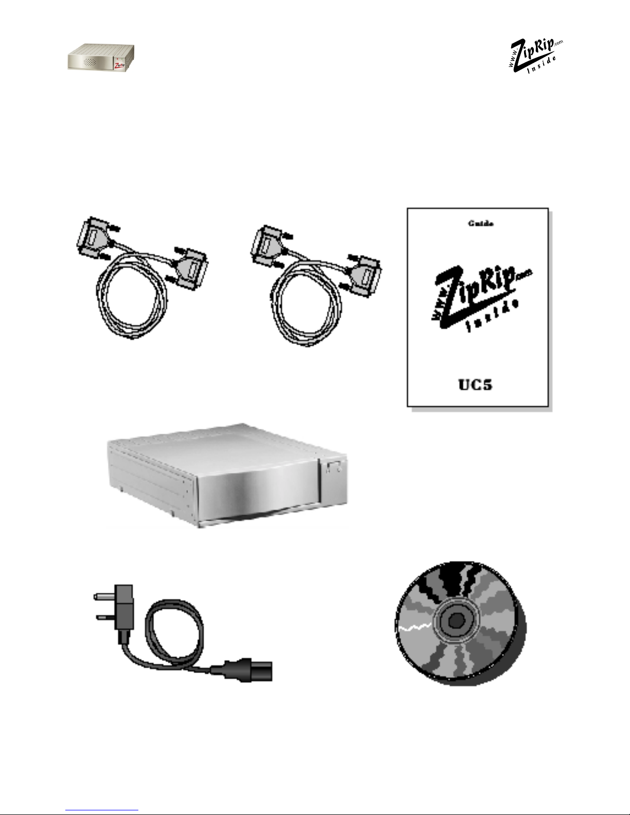
Package Contents
Components For UC5.
Check that you have received the following Items in your UC5 package.
Cable for connecting
to Digital Duplicator Centronics Parallel
Cable
This User Guide
ZipRIP - UC5
Power Cable Installation CD

UC5 IM 1-6 April 2002 9
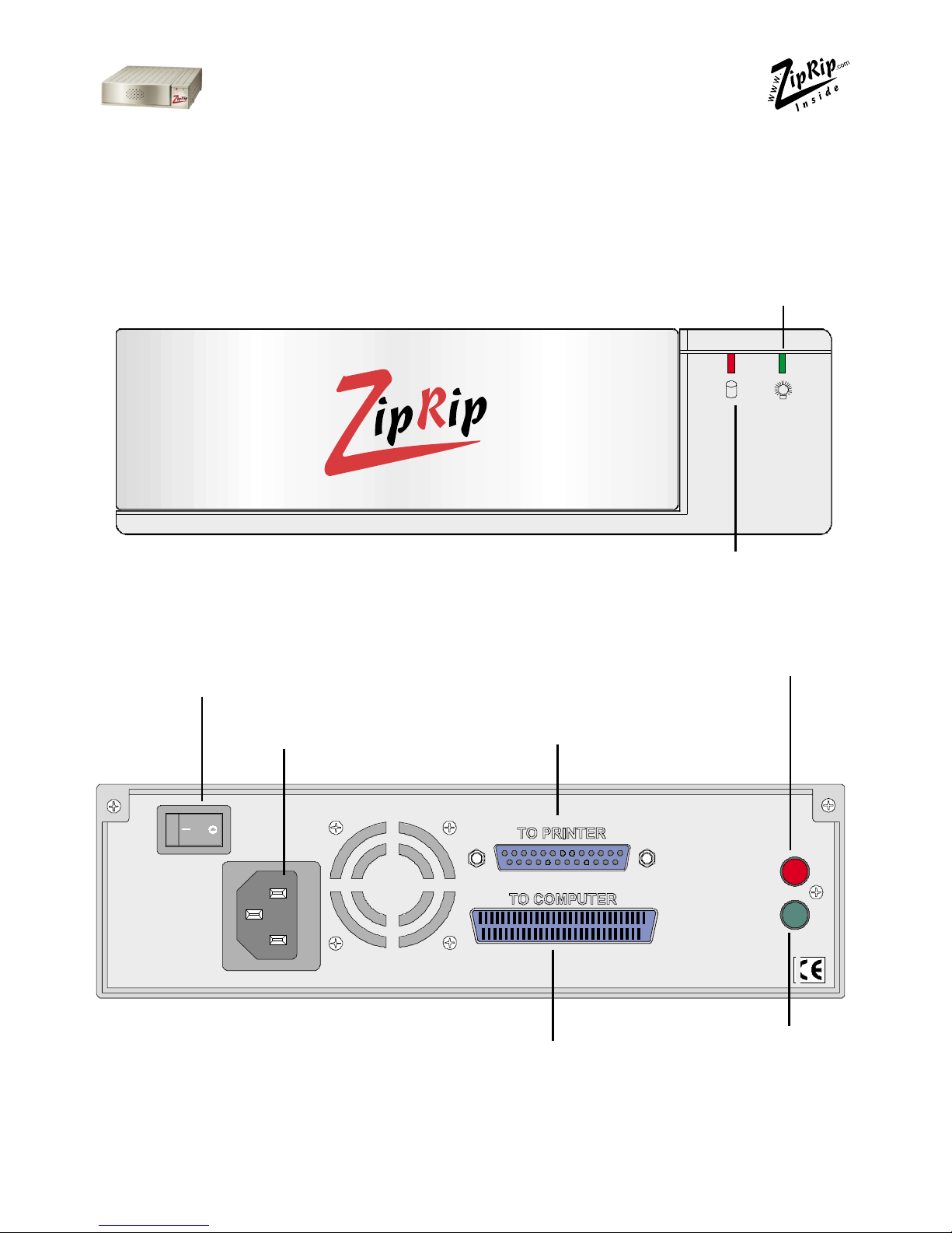
External Features
All indicators and plugs referred to in this manual are described in the
diagrams below.
“Power On”
Indicator (Green)
“Activity” Indicator (Red)
Power switch.
Power socket
Connect using supplied
cable to Digital Duplicator
“Reset” button.
Connect using supplied centronics
cable to PC parallel port.
“Test Page”
button.

10 UC5 IM 1-6 April 2002
Installation of Vi eo Interface PCB an cabling
NOTE: Video I/F Kit Type- 600, Type- 10, Type- 15, and Type- 85 are
Ricoh part plea e obtain from upplier.
Before you begin the installation, you should:
a. Check to make sure that you have all of the items needed to complete
a successful installation.
b. Read the documentation to familiarize yourself with the installation
procedures.
c. Have the following additional items available:
- Service manual for relevant machine
- User’s Guide
- A container to hold screws and other removed components
- Tool Kit

UC5 IM 1-6 April 2002 11
Vi eo I/F Installation Proce ures
Video I/F Kit Type-600 Parts List
Common A emblie
No. De cription Qty.
1 IC -Interface 1
2 Interface Board 1
3 Insulating sheet -1 5 -200 1
Interface Cable -Interface Board 1
Set for Part 1A
No. De cription Qty.
5 Stud -50mm 2
6 Spacer -10mm 2
7 PCB Stud -6 mm 2
8 Harness Support Bracket 1
9 Phillips Pan Head Screw -M3 x 35 1
10 Phillips Flange Screw -M3 x 8 3
11 Phillips Flange Screw -M x 8 3
12 Flat Cable -N810/NA33/NA3/NB2/RN925/N850 1
13 Wire Band 1
1 PCB Collar 1

12 UC5 IM 1-6 April 2002
Set for 1 B
No. De cription Qty.
15 Flat Cable -NA2 1
16 Main Board Spacer 1
17 Stud -Bracket -Interface 2
18 Interface Board Bracket 1
19 Phillips Screw with Flat Washer -M3 x 25 1
20 Stud -Main Board 1
21 Phillips Screw with Flat Washer -M x 6 1
22 Phillips Screw -M x 8 2
23 Phillips Screw with Flat Washer -M3 x 6 2
Set for 1C
No. De cription Qty.
2 Interface Board Stud 2
25 Main Board Stud -Long
26 Phillips Screw -M x 8 2
27 Phillips Screw with Flat Washer -M3 x 6
28 Flat Cable -N865 1

UC5 IM 1-6 April 2002 13
Part for 1D
No. De cription Qty.
29 Stud -35 mm 3
30 Phillips Screw with flat washer -M3 x 6 3
31 Phillips Screw -M x 8 2
Video I/F Kit Type-10, Type-15 and Type- 85 Part Li t
For: Europe, Far East and Asia use Type-10 Interface kit.
For: USA and Latin America use Type-15 Interface kit.
Installation procedure for both Interface kits follow.
No. De cription Qty.
32 Interface Board 1
33 Relay Harness 1
3 Stepped Screw -M2 x.6 2
35 Tapping Screw -M3 x 6 2

14 UC5 IM 1-6 April 2002
Installation Proce ures for Interface Kits
NOTE:
1) The UC5 Controller is designed for all Digital Duplicators.
2) Numbers in parentheses ()in the installation procedures correspond to
the part numbers on pages 8 to 10.
Model C229, C232 and C233
Refer to Driver Group Li t on page 7
NOTE: The interface kit is required. If the kit is standard you must
perform step 3 only to connect the controller .
1. Remove the rear cover and right side panel of the Digital Duplicator.
2. Mount Printed Circuit Board (32)
on connector CN102 of the MPU
board using two M3x6 screws (35).
Mount the cable (33) on the Con-
nector Bracket using two stepped
screws (3 ).
3. Remove the blinding cover in the
right side panel.
NOTE:
Select A3 for paper size in initial set-
ting (the default setting is Auto).
The On-line key is enabled automati-
cally when the controller and interface
kit are installed.
CN102 rinted
Circuit
Board
Harness
Connector Bracket
Binding Cover

UC5 IM 1-6 April 2002 15
Model C231 and C237
Refer to Driver Group Li t on page 7
1. Turn off the main switch and unplug the power cord.
2. Remove the upper rear cover.
3. Remove the MPU cover.
. Connect CN102 of the printed circuit board (32) to CN110 of the MPU
board and secure it using two screws (35).
5. Connect the harness (33) to CN101 of the printed circuit Board, and se-
cure it to the connector bracket using two stepped screws (3 ).
6. Remove the communications port cover plate (blinding cover) from the
upper rear cover.
7. Reinstall the MPU cover.
8. Reinstall the upper rear cover.
NOTE:
The On-line key on the operation panel is enabled automatically when
the controller and interface kit are installed.
rinted Circuit Board
M U
Harness
Connector
Bracket

16 UC5 IM 1-6 April 2002
Model C238
Refer to Driver Group Li t on page 7
1. Remove the rear covers [A] [B] (8 screws).
2. Remove the I/F connector cover [C] (2 screws).
3. Install the I/F board [D] (accessories) in CN117 [E] on the MPU (2 screws).
. Attach the cable [F] (accessories) to the connector bracket (2 screws) and
clamp the cable (6 clamps).
5. Connect the connector [G] at the opposite end to the I/F board.
6. Re-install the rear covers.

UC5 IM 1-6 April 2002 17
Model C239 and C244
Refer to Driver Group Li t on page 7
1. Remove the rear cover [A].
2. Cut away the blindfold cover [B] on the right rear cover.
3. Install the Video I/F board [C] to the MPU. (2 screws)
. Connect the cable [D] to the Video I/F board. (2 screws, 2 spacers)
NOTE: You need to adju t the length of the harne u ing the bind [E]
enclo ed.
5. Reinstall the rear cover.

18 UC5 IM 1-6 April 2002
Model C210, C218 and C223
Refer to Driver Group Li t on page 7
1. Remove the rear cover and front side panel of the Digital Duplicator.
2. Mount the Shielded Cable Interface (2).
a) Mount a Stud (17) on the rear chassis of the Digital Duplicator.
b) Thread the Shielded Cable ( ) from rear chassis to the front chassis
under the Digital Duplicator body.
Note for the VT3600/3500/2600: first remove the bottom plate, then
reattach it.
c) Attach the Shielded Cable ( ) on the Stud (17) using two M x8 Screws (26).
NOTE:
Before mounting Printed Circuit Board Interface (2), attach one end of
the Ribbon Cable (12) to the IPU board ribbon cable connector.
3. Mount the Printed Circuit Board Interface (2).
a) Mount a Stud (20) on the Digital
Duplicator.
b) Mount the Bracket (18) on the
chassis using a M x6 screw and
washer (21).
c) Attach the Printed Circuit Board
(2) using 2, M3x6 screws (27). At-
tach the bottom of the right hand
side of the Printed Circuit Board to
the Spacer (16) using a M3x25
screw (19).
d) Attach the connector of the
Printed Circuit Board (2) to the
Shielded Cable ( ).
e) Attach free end of the Ribbon
Cable (21) to the Printed Circuit
f) Board Interface (2).
M4x6
Screw
Interface
Board
Stud
M3x6
Screws M3x25 Screw
Ribbon
Cable
Spacer
I U board
Bracket

UC5 IM 1-6 April 2002 19
. Set the Printed Circuit Board interface switches.
a) Set all switches on DIPSW 101 to OFF.
5. Reattach the side cover panels of the Digital Duplicator.
a) Pop out the communication port cover plate from the lower centre of
the rear cover panel.
b) Reinstall the rear and front cover panels.
6. Connect the Digital Duplicator and AC power to the Controller.
a) Connect a Video Cable between the Digital Duplicator and the
Controller.
b) Connect an AC cable to the Controller.
7. Set SP Mode 1 (for the On-line Key On/Off) to ON.
Communication port cover

20 UC5 IM 1-6 April 2002
Model C222
1. Remove the rear cover and front side
panel of the Digital Duplicator.
2. Mount Shielded Cable Interface ( ).
3. Mount Printed Circuit Board
Interface (2).
a) Remove the three screws at-
taching the mainframe MPU Board
to the chassis (two screws upper
and lower side of CN109, and one
screw lower side of the CN111).
b) Replace the screws removed in
a) above with Studs (29).
c) Connect one side of the Ribbon
Cable (12) to the connector of
Mainframe MPU Board.
d) Attach the Printed Circuit Board
Interface (2) to the Studs (29) us-
ing M3x6 Screws (27).
e) Connect the free end of the Rib-
bon Cable (12) to the CN102 con-
nector of Printed Circuit Board In-
terface (2).
f) Set all switches of DIPSW 101
on the Printed Circuit Board Inter-
face (2) to OFF.
. Pop out the communication port
cover plate from the lower centre
of the rear cover panel. Reinstall the
rear and front cover panels.
5. Set SP Mode 2-1 (On-line Key On/
Off) to ON.
Shielded Cable Studs
rinted Circuit Board Interface
Other manuals for UC5
1
Table of contents