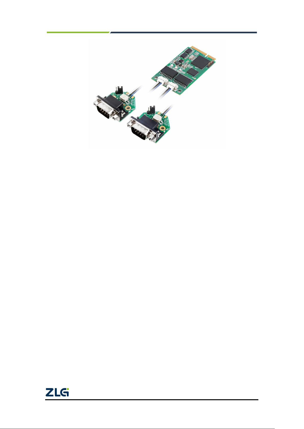
ZLG MiniPCIeCAN-2E-U User manual

Product User Manual
MiniPCIeCAN-2E-U
MiniPCIe Interface CAN Card
User Manual
UM01010101 V1.05 Date: 2020/11/04
Category
Contents
Keywords
MiniPCIe and CAN message monitoring
Description
MiniPCIe interface CAN card
©2021 Guangzhou ZLG Microelectronics Technology Corp.,Ltd.

MiniPCIeCAN-2E-U
MiniPCIe Interface CAN Card User Manual
©2021 Guangzhou ZLG Microelectronics Technology Corp.,Ltd.
i
User Manual
Revision History
Version
Date
Reason
V0.00
July 1, 2015
Created
V1.01
September 30,
2015
Added quick instructions and dynamic library usage.
V1.02
August 9, 2017
Changed the company name, sales and service network
V1.03
September 3, 2018
Modified product dimensions.
V1.04
March 12, 2019
Updated the document header and footer and "Sales and
Service Network" content and added the "Disclaimer" content
V1.05
November 04,
2020.
Added the MiniPCIe slot description

MiniPCIeCAN-2E-U
MiniPCIe Interface CAN Card User Manual
©2021 Guangzhou ZLG Microelectronics Technology Corp.,Ltd.
1
User Manual
Contents
1. Functions .....................................................................................................2
1.1 Typical application.............................................................................................3
2. Equipment Installation..................................................................................4
2.1 Power Supply.....................................................................................................4
2.2 Signal Indicators................................................................................................4
2.3 MiniPCIe Interface Definitions...........................................................................5
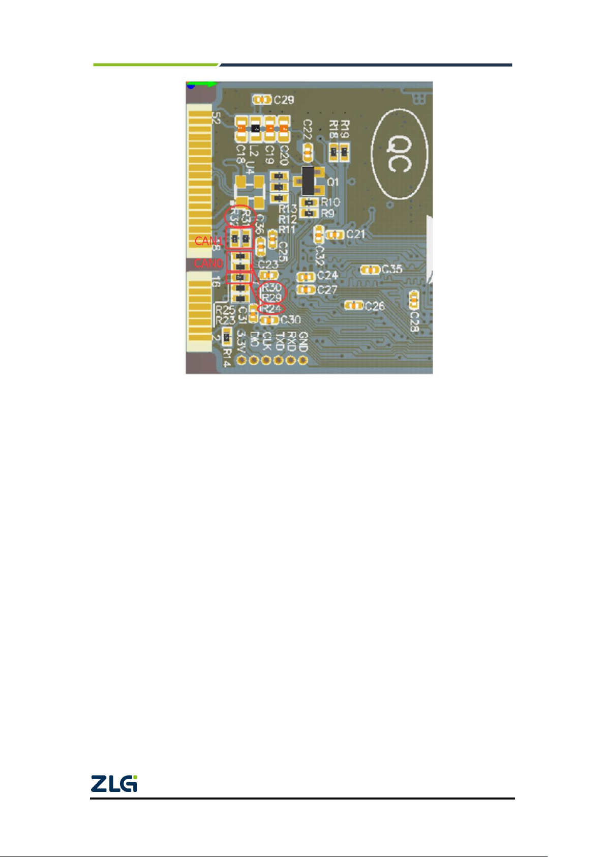
2.4 CAN Second Function Pin Switch.....................................................................5
3. Driver Installation.........................................................................................7
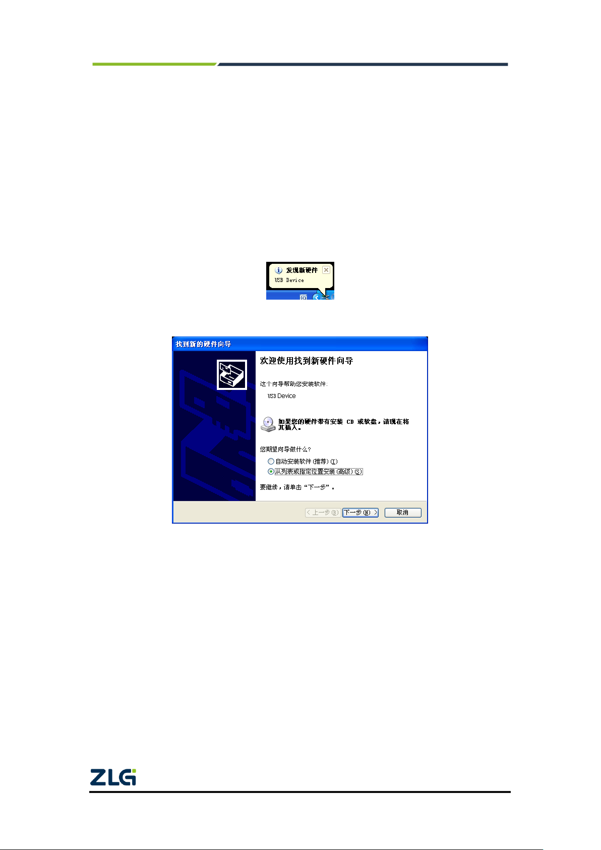
3.1 Driver Installation...............................................................................................7
3.2 Uninstalling the Device Driver .........................................................................11
4. Quick Instructions ......................................................................................12
4.1 CANTest Basic Operations..............................................................................12
4.1.1 Device Type Selection..............................................................................12
4.1.2 Filter Settings ...........................................................................................13
4.1.3 Starting the CAN ......................................................................................14
4.1.4 Getting Device Information.......................................................................14
4.2 Sending and Receiving Test............................................................................14
4.2.1 Establishing a Test Environment..............................................................14
4.2.2 Starting the Device...................................................................................16
4.2.3 Sending Data............................................................................................18
4.2.4 Real-time Saving and Stopping Saving ...................................................19
4.2.5 DBC Decoding and Display by ID............................................................19
4.2.6 Bus Utilization...........................................................................................20
4.2.7 Error Message Display.............................................................................20
5. Method of Using The Interface Library Functions ......................................22
5.1 Methods of Calling the Dynamic Library on Windows.....................................22
5.1.1 Methods of VC Calling the Dynamic Library............................................22
5.1.2 Method of VB Calling the Dynamic Library..............................................22
5.2 Interface Library Function Usage Process......................................................24
6. Electrical Characteristics............................................................................25
7. Structure and Dimensions..........................................................................26
8. Inspection and Maintenance......................................................................28
9. Disclaimer..................................................................................................31
Appendix AARM standard baud rate.............................................................32

MiniPCIeCAN-2E-U
MiniPCIe Interface CAN Card User Manual
©2021 Guangzhou ZLG Microelectronics Technology Corp.,Ltd.
2
User Manual
1. Functions
MiniPCIeCAN-2E-U is a high-performance MiniPCIe interface CAN card launched by
ZLG Electronics, which can connect the CAN network to a computer equipped with a
MiniPCIe card slot. MiniPCIeCAN-2E-U adopts the MiniPCIe board in standard
dimensions and can be easily installed on laptop or industrial computer with MiniPCIe
interface, making it a powerful CAN analyzer. See the figure. .
MiniPCIeCAN-2E-U integrates two CAN interfaces. In addition, to facilitate expansion,
the second function pin of the CAN signal can be switched to the reserved IO port of the
MiniPCIe interface by using the resistor R24, which helps the user design the CAN
transceiver circuit on the backplane.
The MiniPCIeCAN-2E-U high-performance CAN interface card can be used to
connect the PC to the CAN-bus network through USB bus, which constitutes a CAN-bus
network control node for data processing and data acquisition in CAN-bus network fields
such as fieldbus laboratories, industrial control, high-performance residential areas, and
automotive electronic networks.
The MiniPCIeCAN-2E-U high-performance CAN interface card is a powerful tool for
CAN-bus product development and CAN-bus data analysis; moreover, it features small
size, plug and play, etc. It is ideal for portable system users.
The MiniPCIeCAN-2E-U high-performance CAN interface card supports Windows
2000/XP/7/8/10 and other operating systems. MiniPCIeCAN-2E-U provides a unified
application programming interface and complete application demonstration codes,
including VC, VB, Delphi and C++ development routine demonstrations, which helps
users develop application programs.
The MiniPCIeCAN-2E-U interface card supports the CANTest general test software,
which can perform functions such as sending, receiving and monitoring CAN-bus
messages.
The MiniPCEeCAN card uses the USB D+ and USB D- signal cable in the MiniPCIe
slot. Before purchasing and using the product, check whether the MiniPCIe slot on the
motherboard provides USB D+ and USB D- signal pins. See Table 2.3 for pin numbers.
This CAN card cannot be used if the USB signal pin is missing from the motherboard slot.

MiniPCIeCAN-2E-U
MiniPCIe Interface CAN Card User Manual
©2021 Guangzhou ZLG Microelectronics Technology Corp.,Ltd.
3
User Manual
Figure 1.1 Product functions
Adopt the standard MiniPCIe interface;
Support CAN2.0A and CAN2.0B protocols, in line with ISO/DIS11898
specification;
Integrated two CAN-bus interfaces;
The CAN TTL signal can be switched to the second function IO, which helps
design the CAN transceiver circuit by yourself;
The CAN-bus communication baud rate can be arbitrarily programmable
between 5 Kbps and 1 Mbps;
Powered by the MiniPCIe interface;
The CAN-bus interface is electrically isolated. The insulation voltage of the
isolation module is 2,500 V DC;
Support Windows 2000, Windows XP, Windows 7, Windows 8, Windows 10
operating systems;
Support the CANtest test software;
Compact, plug and play;
Operating temperature: -40℃to 85℃;
Standard MiniPCIe card dimensions: 30 mm (width) x 50.95 mm (length).
1.1 Typical application
CAN-bus network diagnosis and test;
Automotive electronics applications;
Electrical communication;
Network industrial control equipment;
High-speed, large data volume communication.

MiniPCIeCAN-2E-U
MiniPCIe Interface CAN Card User Manual
©2021 Guangzhou ZLG Microelectronics Technology Corp.,Ltd.
4
User Manual
2. Equipment Installation
2.1 Power Supply
MiniPCIeCAN-2E-U uses the MiniPCIe interface 3.3V power supply. The SYS
indicator is on, and it turns red first, indicating that the device has power supply. It then
flashes a few times and turns green, indicating communication with the PC.
2.2 Signal Indicators
The MiniPCIeCAN-2E-U interface card has one dual-color SYS indicator, one
dual-color CAN0 indicator, and one dual-color CAN1 indicator, which indicate the running
status of the device. Table 2.1 lists the functions of the indicators. When the indicators are
in various states, the status of the CAN bus is shown in Table 2.2.
Table 2.1 Indicator functions
Indicator
STATUS
Indication status
SYS
Red
Device initialization status indication
Green
MiniPCIe interface signal indication
CAN1
Green
The CAN interface is working properly
Red
The CAN interface is faulty
CAN2
Green
The CAN interface is working properly
Red
The CAN interface is faulty
After the MiniPCIeCAN-2E-U interface card is powered on, the system initialization
status indicator SYS is red, indicating that the device has been powered and the system is
initializing;If the system initialization status indicator SYS is off, a system power fault or
serious system error occurs.
After normal connection to the PC, the SYS indicator is green. When data is being
transmitted on the USB interface, the USB signal indicator SYS flashes in green.
When CAN1 and CAN21 indicators are green, the CAN controller has been initialized
and is working properly.
When the CAN controller has an error, the CAN1 and CAN2 indicators are red; when
the error of the CAN controller is cleared, the CAN1 and CAN2 indicators are green.
Table 2.2 CAN bus status
CAN indicator status
CAN bus status
CAN1, CAN2 are all off
The CAN controller is disconnected from the bus
CAN1 and CAN2 flash alternately in
red and green
The CAN controller is not started, and the user is prompted to
start the CAN controller
CAN1 and CAN2 indicators are
always green
The CAN bus is operating properly
CAN1, CAN2
The red indicator flashes
The CAN-bus bus has an error or data overflow, and it may lose
frames

MiniPCIeCAN-2E-U
MiniPCIe Interface CAN Card User Manual
©2021 Guangzhou ZLG Microelectronics Technology Corp.,Ltd.
5
User Manual
2.3 MiniPCIe Interface Definitions
Figure 2.1 MiniPCIe pin sequence
Table 2.3 MiniPCIe interface definition
Signal Name
Pin No.
Description
nWAKE
1
nWAKE signal/default pull-up
nRESET
22
nRESET signal/not used
TD0_REV
17
CAN0 TD second function IO
RD0_REV
19
CAN0 RD second function IO
TD1_REV
37
CAN1 TD second function IO
RD1_REV
39
CAN1 RD second function IO
USB_D-
36
USB_D-
USB_D+
38
USB_D+
3.3V
2, 24, 52
Power supply
GND
9, 15, 18, 21, 26, 27, 29, 34, 35,
40, 50
Ground
2.4 CAN Second Function Pin Switch
When designing the CAN transceiver circuit or improving the protection level of the
CAN signal cable, consider connecting the second function pin of the CAN signal to the
backplane through the MiniPCIe reserved pin. Design the CAN transceiver circuit by
yourself to improve the system flexibility.

MiniPCIeCAN-2E-U
MiniPCIe Interface CAN Card User Manual
©2021 Guangzhou ZLG Microelectronics Technology Corp.,Ltd.
6
User Manual
Figure 2.2 CAN signal secondary function selection resistor
The second function pin of the CAN signal is switched by using R24 (this resistor can
be found on the rear of the board, as shown in Figure 2.2). R24 is welded by default. The
system uses the default on-board CAN transceiver ADM3053. When R24 is removed, the
second function pin of the CAN signal is automatically enabled when the system is
powered on. Table 2.3 lists the pin sequence. At this time, R29 and R30 need to weld 0
ohm resistors to enable CAN0, while R31 and R32 respectively weld 0 ohm resistors to
enable CAN1.

MiniPCIeCAN-2E-U
MiniPCIe Interface CAN Card User Manual
©2021 Guangzhou ZLG Microelectronics Technology Corp.,Ltd.
7
User Manual
3. Driver Installation
The following uses a PC running WinXP as an example to illustrate how to install a
MiniPCIeCAN-2E-U series industrial-grade high-performance CAN interface card device
correctly.
3.1 Driver Installation
Windows XP can automatically detect new devices (as shown in Figure 3.1) and
activate the "Found New Hardware Wizard" program to install plug-and-play device
drivers (as shown in Figure 3.2). If the system does not prompt to discover a new device
at this time, check whether the hardware is installed properly.
Figure 3.1 Discovering new hardware on Windows XP
Figure 3.2 New Hardware Driver Installation Wizard
Select "Install from a list or specified location", and click "Next". See Figure 3.3.

MiniPCIeCAN-2E-U
MiniPCIe Interface CAN Card User Manual
©2021 Guangzhou ZLG Microelectronics Technology Corp.,Ltd.
8
User Manual
Figure 3.3 Getting the driver file directory
Mark "Include this location in search" and click the "Browse" button. In the displayed
folder browsing dialog box, specify the location of the driver installation file (the location of
the driver in the product CD-ROM is MiniPCIeCAN-2E-U\drivers\XP driver, and
MiniPCIeCAN-2E-U is the USBCAN-2E-U Derivatives, therefore sharing a single driver).
Click Next. See Figure 3.4.
Figure 3.4 Installing the driver
Wait until the installation wizard installs the driver. The next window shows the
installed devices. If the "Found New Hardware Wizard" message appears, the driver has
been installed. Click the "Finish" button to complete the installation. See Figure 3.5

MiniPCIeCAN-2E-U
MiniPCIe Interface CAN Card User Manual
©2021 Guangzhou ZLG Microelectronics Technology Corp.,Ltd.
9
User Manual
Figure 3.5 Driver installation complete
Check the device installation in "Start > Control Panel > System". Click the
"Hardware" tab, and click the "Device Manager" button. See Figure 3.6 and Figure 3.7.
Figure 3.6 Hardware Wizard

MiniPCIeCAN-2E-U
MiniPCIe Interface CAN Card User Manual
©2021 Guangzhou ZLG Microelectronics Technology Corp.,Ltd.
10
User Manual
Figure 3.7 Checking device driver installation

MiniPCIeCAN-2E-U
MiniPCIe Interface CAN Card User Manual
©2021 Guangzhou ZLG Microelectronics Technology Corp.,Ltd.
11
User Manual
3.2 Uninstalling the Device Driver
You can uninstall the device driver in "Start > Control Panel > System". Click the
"Hardware" tab, and click the "Device Manager" button. See Figure 3.8.
Figure 3.8 Hardware wizard
Right-click "USBCAN-2E-U" and choose "Uninstall". See Figure 3.9.
Figure 3.9 Unloading the device driver
In the Confirm Device Removal dialog box, click OK. The driver for USBCAN-2E-U
will be uninstalled. Device Manager will be automatically refreshed and show that the
device has been removed. See Figure 3.10.
Figure 3.10 Confirming device driver uninstallation

MiniPCIeCAN-2E-U
MiniPCIe Interface CAN Card User Manual
©2021 Guangzhou ZLG Microelectronics Technology Corp.,Ltd.
12
User Manual
4. Quick Instructions
4.1 CANTest Basic Operations
The CANtest test software can be found in the supporting CD-ROM (need to be
installed). See Figure 4.1.
Figure 4.1 CANTest software icon
Note: The download address of CANTest software is
http://www.zlg.cn/canbus/product_detail.php?id=4.
4.1.1 Device Type Selection
Before operation, select USBCAN-2E-U from the "Select Device" menu, as shown in
Figure 4.2.
Figure 4.2 Device type selection

MiniPCIeCAN-2E-U
MiniPCIe Interface CAN Card User Manual
©2021 Guangzhou ZLG Microelectronics Technology Corp.,Ltd.
13
User Manual
The "Open Device" dialog box is displayed, as shown in Figure 4.3.
Figure 4.3 Open Device dialog box
In this dialog box, select the device index number and CAN channel to be opened,
and set the CAN initialization parameters, click "OK" to open the device operation window
(or you can click the "OK and start CAN" button to open the device operation window and
automatically start the device and start the CAN channel).
4.1.2 Filter Settings
In the device operation window, click the "Filter Settings" button to set the filter (if you
do not need to set the filter, you can skip this step), as shown in Figure 4.4.
Figure 4.4 Filter Setting 1
The Filter Settings dialog box is displayed, as shown in Figure 4.5.

MiniPCIeCAN-2E-U
MiniPCIe Interface CAN Card User Manual
©2021 Guangzhou ZLG Microelectronics Technology Corp.,Ltd.
14
User Manual
Figure 4.5 Filter Setting 2
Select the filter mode. Set the CAN frame to be filtered by setting the filter.
4.1.3 Starting the CAN
Click the "Start" button to start the CAN channel. The received CAN data is
automatically displayed in the data list, as shown in Figure 4.6.
Figure 4.6 Startup
4.1.4 Getting Device Information
Figure 4.7 Device information
After starting the CAN channel, select the "Device Information" option in the "Device
Operation" menu to obtain the details of the current device, as shown in Figure 4.7.
4.2 Sending and Receiving Test
This section describes the simple transmit-receive test, DBC decoding, and bus
utilization of MiniPCIeCAN-2E-U.
4.2.1 Establishing a Test Environment
Ensure that the wiring is correct. Figure 4.8 shows the interface definition, and Figure
4.9 shows the wiring effect.

MiniPCIeCAN-2E-U
MiniPCIe Interface CAN Card User Manual
©2021 Guangzhou ZLG Microelectronics Technology Corp.,Ltd.
15
User Manual
Figure 4.8 Interface definition
Figure 4.9 Wiring diagram
In this document, it is built based on our company's core board and backplane. In fact,
the driver can be installed as long as the device connected to the MiniPCIe interface is
installed. Figure 4.10 and Figure 4.11 show the overall effect.
Figure 4.10 Wiring diagram

MiniPCIeCAN-2E-U
MiniPCIe Interface CAN Card User Manual
©2021 Guangzhou ZLG Microelectronics Technology Corp.,Ltd.
16
User Manual
Figure 4.11 Wiring diagram
4.2.2 Starting the Device
Run the CANTest software and select the device type. See 4.1.1 Summary. Configure
the device, as shown in Figure 4.12 and Figure 4.13. Pay attention to the selection of CAN
channels. The device index number is a code that identifies the device. The same device
index number should be selected for different CAN interfaces of the same device.
Different device index numbers are selected for different devices select . Generally, device
index numbers start from 0. The number of CAN channels is used to distinguish different
CAN channels under the same device index number. This device has two CAN channels.
Therefore, there are two options (0 and 1) in the first few CAN options. The baud rate is
100K. Since there is no terminal resistor installed for this test, the baud rate should not
exceed 100K. If you really use it, you must add a terminal resistor of the corresponding
resistance value.
Figure 4.12 Parameter setting of the first channel CAN

MiniPCIeCAN-2E-U
MiniPCIe Interface CAN Card User Manual
©2021 Guangzhou ZLG Microelectronics Technology Corp.,Ltd.
17
User Manual
Figure 4.13 Parameter setting of the second channel CAN

MiniPCIeCAN-2E-U
MiniPCIe Interface CAN Card User Manual
©2021 Guangzhou ZLG Microelectronics Technology Corp.,Ltd.
18
User Manual
4.2.3 Sending Data
When you start the CAN successfully, set the parameters of the CAN frame you want
to send, as shown in Figure 4.14. Click the "Send" button to send the data(The self-sent
and self-receive option in the Sending Format drop-down box indicates that the sent CAN
frame can also be received by itself. This option is only needed during testing; select
normal transmission in practical applications).
Figure 4.14 Basic settings for sending data
Click the "Advanced Operation" tab to display the advanced operation page. On this
page, you can set to send multiple different CAN frames each time (a maximum of 100
frames can be set), and the interval between each frame and between each batch, as
shown in Figure 4.15.
Figure 4.15 Advanced settings for sending data
Figure 4.16 and Figure 4.17 show the sending and receiving effect.
Table of contents
Other ZLG PCI Card manuals