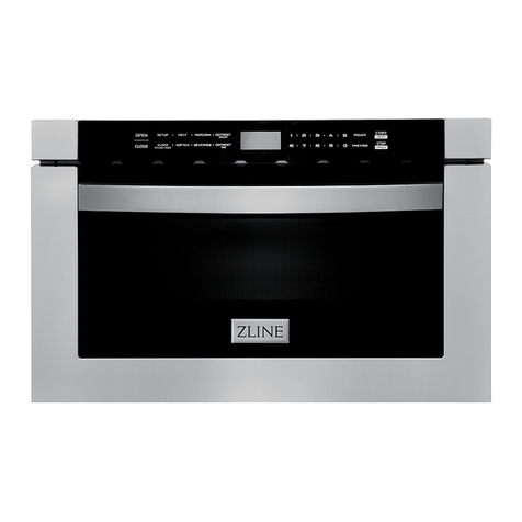
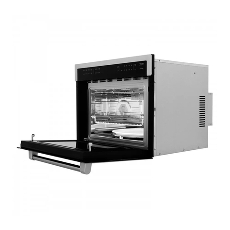
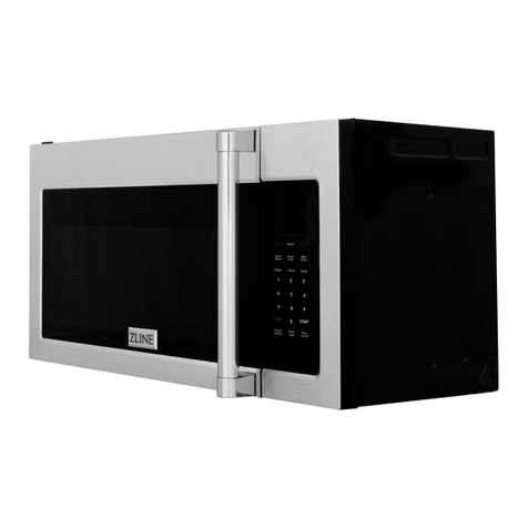
Zline MWO-OTR-30 User manual

OVER THE RANGE
MICROWAVE OVEN
www.zlinekitchen.com
Installation Manual

ZLINE Kitchen and Bath provides Attainable Luxury, where the kitchen and bath of your dreams
is never out of reach. Through our unique designs and unparalleled quality, we’re dedicated to
providing you an elevated experience in the heart of your home. With an endless selection of
features and finishes, our inspiration is your reality.

WARNING: This product can expose you to chemicals including nickel, which is known to the
State of California to cause cancer. For more information, go to www.P65Warnings.ca.gov.
ZLINE is fueled by a passion for innovation; A relentless pursuit of bringing the highest end luxury
designs and professional features into everyone’s homes. Because we continually strive to improve
our products, we may change specifications and designs without prior notice.

1
General Safety
SAFETY INSTRUCTIONS
WARNING
Before operation, please read and follow these
important instructions for the safety of your home
and the people living in it.
• When using electrical appliances, basic safety
precautions should be followed, including the following:
• Install or locate this appliance only in accordance with
the provided installation instructions.
• This appliance is intended to be used in households and
similar applications such as: staff kitchen areas in shops,
offices, and other working environments; by clients in
hotels, motels, and other residential type environments;
farm houses; and bed and breakfast type environments.
• Do not attempt to operate this oven with the door open.
This can result in harmful exposure to microwave energy.
• Do not break or tamper with the safety interlocks.
• Do not place any object between the oven front face
and the door or allow soil or cleaning residue to
accumulate on sealing surfaces.
• Do not operate the oven if it is damaged. It is particularly
important that the oven door closes properly and that
there is no damage to the:
• Door (bent or broken)
• Hinges and latches (broken or loosened)
• Door seals and sealing surfaces (dirty or eroding)
• The oven should not be adjusted or repaired by anyone
except properly qualified service personnel.
• If the oven is not maintained in a good state of
cleanliness, its surface could be degraded and affect the
lifespan of the oven and lead to a dangerous situation.
2
General Safety
SAFETY INSTRUCTIONS
• Use this appliance only for its intended use as described
in the manual. Do not use corrosive chemicals or vapors
in this appliance
• This type of oven is designed to heat, cook, or defrost
food. It is not designed for industrial or laboratory use.
• Do not use harsh abrasive cleaners or sharp metal
scrapers to clean the oven door glass since they can
scratch the surface, which may result in shattering.
• Heavily soiled seal: If the seal is very dirty or eroded,
the appliance door will no longer close properly during
operation. The fronts of adjacent units could also be
damaged. Always keep the seal clean.
• This appliance can be used by children if they have been
given supervision or instruction on use of the appliance
in a safe way and understand the hazards involved.
• Children shall not play with the appliance. Cleaning and
user maintenance shall not be made by children without
supervision. Keep the appliance and its cord out of
reach of children without supervision.
• If the electrical cord is damaged, it must be replaced by
the manufacturer or a similarly qualified professional in
order to avoid a hazard.
• Do not immerse cord or plug in water.
• Keep cord away from heated surface.
• Do not let cord hang over edge of table or counter.
• Do not cover or block any openings on the appliance.
• Do not store this appliance outdoors. Do not use near
water — for example, near a kitchen sink, in a wet
basement, near a swimming pool, or similar location.

3
Fire Safety
SAFETY INSTRUCTIONS
• To reduce the risk of fire inside the oven:
• Do not overcook food. Carefully oversee appliance
when paper, plastic, or other combustible materials
are placed inside the oven to facilitate cooking.
• Remove wire twist-ties from paper or plastic bags
before placing bags in oven.
• If material inside the oven ignites, keep oven door
closed, turn oven off, and disconnect power cord or shut
off power at the circuit breaker.
• Do not use the microwave for storage purposes.
• Do not leave paper products, cooking utensils, or
food inside when not in use.
• If smoke is emitted, switch off and unplug the appliance
and keep the door closed in order to stifle any flames.
• Care should be taken not to displace the turntable when
removing containers from the appliance.
• Some products, such as whole eggs and sealed
containers — for example, closed glass jars — can
explode and should not be heated in this oven.
WARNING
Liquids and other foods must not be heated in
sealed containers since they are liable to explode.

4
Food Safety
SAFETY INSTRUCTIONS
• Liquids such as water, coffee, or tea may be heated
beyond the boiling point without appearing to be
boiling. Visible bubbling or boiling when the container
is removed from the microwave oven is not always
present. THIS COULD RESULT IN VERY HOT LIQUID
SUDDENLY BOILING OVER WHEN THE CONTAINER
IS DISTURBED OR A UTENSIL IS INSERTED INTO THE
LIQUID. To reduce the risk of injury to persons:
• Do not overheat the liquid.
• Stir the liquid both before and halfway through
heating it.
• Do not use straight-sided containers with narrow
necks.
• After heating, allow the container to stand in the
microwave oven for a short time before removing
the container.
• Use extreme care when inserting a spoon or other
utensil into the container.
• Do not store anything directly on top of the appliance
surface when the appliance is in operation.
• Oversized food or oversized metal utensils should not be
inserted in the oven as they may create a fire or risk of
electric shock.
• The appliance shall not be cleaned with a steam cleaner.
• Do not clean with metal scouring pads. Pieces can burn
off the pad and touch electrical parts, increasing the risk
of electric shock.
• Do not store any materials, other than manufacturer’s
recommended accessories, in this oven when not in use.
• Do not cover racks or any part of the oven with metal
foil.

5
Food Safety
SAFETY INSTRUCTIONS
• When heating food in plastic or paper containers, keep
an eye on the oven due to the possibility of ignition.
• Only use utensils suitable for use in microwave ovens.
• The contents of feeding bottles and baby food jars must
be stirred or shaken and the temperature checked before
consumption in order to avoid burns.
• The oven should be cleaned regularly and any food
deposits removed since they may explode even after
microwave heating has ended.
• The microwave oven is intended for heating food and
beverages. Drying of food or clothing and heating of
warming pads, slippers, sponges, damp cloths, and
similar items may lead to risk of injury, ignition, or fire.
WARNING
The appliance and accessible parts become hot
during use. Care should be taken to avoid touching
heating elements. Metallic containers for food and
beverages are not allowed during microwave
cooking.
• The appliance is intended to be used built-in.
• The appliance must not be installed behind a decorative
door in order to avoid overheating.
• Using metal, aluminum, or other non-microwave-safe
objects in the microwave function can cause sparks.
Sparks can irreparably damage the glass on the inside
the of the door.
• Never pour water inside the oven. This will cause steam.
The temperature change can cause damage.
• Do not store moist food in the oven for long periods.
• Do not use the appliance to store food. This can lead to
corrosion.

6
Placement Safety
SAFETY INSTRUCTIONS
• Do not trap anything in the appliance door. Even if the
door is only slightly ajar, the fronts of adjacent units may
be damaged over time.
• Do not operate the microwave without food inside.
Doing so may lead to power overloading. Never switch
on the appliance unless there is food in the cooking
compartment.
• When using the convection bake/roast or convection
+ micro features, the plastic coupler and turntable ring
inside the unit do NOT need to be removed; neither will
be impacted by these forms of cooking.
• Do not operate any heating or cooking appliance
beneath, over, or near the appliance. It is okay to use
the microwave above another heating appliance.
• This appliance is suitable for use above both gas and
electric cooking equipment.
• Do not mount over any sinks.
• Do not store anything directly on top of the appliance
surface when the appliance is in operation.
• Clean ventilation hoods frequently. Grease should not be
allowed to accumulate on the hood or filters.
• Use care when cleaning the vent-hood filter. Corrosive
cleaning agents may damage the filter.

7
Electrical Connection
BEFORE INSTALLATION
ELECTRIC SHOCK HAZARD
WARNING
• Before you plug in an electrical cord or turn on power supply, make sure all controls
are in the OFF position. Before installing, turn power OFF at the service panel.
• Connect the appliance only to properly grounded outlet. Improper grounding may
result in electrical shock. Consult a qualified electrician if the grounding instructions
are not completely understood, or if doubt exists as to whether the appliance is
properly grounded.
• Do not cut or remove the ground prong. It must be plugged into a matching
grounding type receptacle to avoid electrical shock.
• Installation, electrical connections, and grounding must comply with all applicable
codes. In the event of a short circuit, grounding reduces the risk of electric shock by
providing an escape wire for the electric current.
WARNING
Improper use of the grounding can result in a risk of electric shock.
• If it is necessary to use an extension cord, use only a 3-wire cord that has a 3-prong
grounded plug and a 3-slot receptacle. The marked rating of the extension cord shall
be equal to or greater than the electrical rating of the appliance.
• Only a qualified electrician who takes the appropriate regulations into account may
install the socket or replace the connecting cable.
• Touching some of the internal components of this appliance can cause serious
personal injury or death. Do not disassemble this product. Improper use of the
grounding can result in electrical shock. Do not plug into an outlet until appliance is
properly installed and grounded.
• A short power-supply cord is provided to reduce the risks resulting from becoming
entangled in or tripping over a longer cord.
WARNING
We do not recommend using an extension cord and if used on this appliance,
it will void warranty. If you use an extension cord, make sure the wire gauge
and length are correct for use with a microwave. The use of an extension cord
can cause voltage drop, fire hazard, and can cause permanent damage to the
microwave if used.

8
Electrical Connection
BEFORE INSTALLATION
ELECTRICAL REQUIREMENTS
• A 3-prong grounded outlet
• 120VAC, 60Hz, NEMA 5-15 plug
• 15-amp electrical supply with a fuse or a circuit breaker
OTHER INSTALLATION NOTES
• For personal safety, remove house fuse or open circuit breaker before beginning
installation to avoid severe or fatal shock injury. Figure 1
• The mounting surface must be capable of supporting the cabinet load, in addition to
the added weight of this product (63-85 pounds, 28.5-38.5 kg), plus additional oven
loads of up to 50 pounds (22.7 kg) for a total weight of 113-135 pounds (51.3-61.2
kg).
• Do not install this product in cabinet arrangements such as an island or a peninsula. It
must be mounted to BOTH a top cabinet AND a wall.
• The power cord of this appliance is equipped with a 3-prong grounding plug that
mates with a standard 3-prong wall receptacle to minimize the possibility of electric
shock hazard from this appliance. Figure 2
• If a 2-prong wall receptacle is encountered, it must be replaced with a properly
grounded 3-prong receptacle by a qualified electrician.
WARNING
Do not under any circumstances cut, deform, or remove any of the prongs
from the power cord.
This product requires a three-prong grounded outlet.
The installer must perform a ground continuity check
on the power outlet box before beginning the
installation to ensure that the outlet box is properly
grounded. If not properly grounded, or if the outlet
box does not meet electrical requirements noted
(under ELECTRICAL REQUIREMENTS), a qualified
electrician should be employed to correct any
deficiencies.
CAUTION: For personal
safety, remove house fuse
or open circuit breaker
before beginning
installation to avoid severe
or fatal shock injury.
CAUTION: For personal safety, the mounting surface
must be capable of supporting the cabinet load, in
addition to the added weight of this 63–85 pound
(28.5–38.5 kg) product, plus additional oven loads of
up to 50 pounds (22.7 kg) or a total weight of
113–135 pounds (51.3–61.2 kg).
CAUTION: For personal safety, this product cannot
be installed in cabinet arrangements such as an island or
a peninsula. It must be mounted to BOTH a top cabinet
AND a wall.
NOTE: For easier installation and personal safety, it is
recommended that two people install this product.
IMPORTANT – PLEASE READ CAREFULLY. FOR
PERSONAL SAFETY, THIS APPLIANCE MUST BE
PROPERLY GROUNDED TO AVOID SEVERE OR
FATAL SHOCK.
The power cord of this
appliance is equipped with a
three-prong (grounding)
plug which mates with a
standard three-prong
(grounding) wall receptacle
to minimize the possibility
of electric shock hazard
from this appliance.
You should have the wall receptacle and circuit checked
by a qualified electrician to make sure the receptacle is
properly grounded.
Where a standard two-prong wall receptacle is
encountered, it is ver y important to have it replaced
with a properly grounded three-prong wall receptacle,
installed by a qualified electrician.
DO NOT, UNDER ANY CIRCUMSTANCES, CUT,
DEFORM OR RE MOVE ANY OF THE PRONGS
FROM THE POWER CORD. DO NOT USE WITH
AN EXTENSION CORD.
IMPORTANT SAFETY INSTRUCTIONS
Ensure proper
ground exists
before use
Installation Instructions
ELECTRICAL
REQUIREMENTS
Product rating is 120 volts AC, 60 Hertz, 15 amps and
1.6 kilowatts. This product must be connected to a
The power supply cord and plug should be brought to a
the prevailing local code for this kilowatt rating.
the requirements of the National Electrical Code or
voltage and frequency. Wire size must conform to
seperate and dedicated supply circuit of the proper
seperate and dedicated 20 ampere branch
National Electrical Code or the prevailing local code.
by a qualifed electrician and conform to the
The outler box and supply circuit should be installed
be located in the cabinet above the microwave oven.
circuit single grounded outlet. The outlet box should
EN-3
Figure 2
This product requires a three-prong grounded outlet.
The installer must perform a ground continuity check
on the power outlet box before beginning the
installation to ensure that the outlet box is properly
grounded. If not properly grounded, or if the outlet
box does not meet electrical requirements noted
(under ELECTRICAL REQUIREMENTS), a qualified
electrician should be employed to correct any
deficiencies.
CAUTION: For personal
safety, remove house fuse
or open circuit breaker
before beginning
installation to avoid severe
or fatal shock injury.
CAUTION: For personal safety, the mounting surface
must be capable of supporting the cabinet load, in
addition to the added weight of this 63–85 pound
(28.5–38.5 kg) product, plus additional oven loads of
up to 50 pounds (22.7 kg) or a total weight of
113–135 pounds (51.3–61.2 kg).
CAUTION: For personal saf ety, this product cannot
be installed in cabinet arrangements such as an island or
a peninsula. It must be mounted to BOTH a top cabinet
AND a wall.
NOTE: For easier installation and personal saf ety, it is
recommended that two people install this product.
IMPORTANT – PLEASE READ CAREFULLY. FOR
PERSONAL SAFETY, THIS APPLIANCE MUST BE
PROPERLY GROUNDED TO AVOID SEVERE OR
FATAL SHOCK.
The power cord of this
appliance is equipped with a
three-prong (grounding)
plug which mates with a
standard three-prong
(grounding) wall receptacle
to minimize the possibility
of electric shock hazard
from this appliance.
You should have the wall receptacle and circuit checked
by a qualified electrician to make sure the receptacle is
properly grounded.
Where a standard two-prong wall receptacle is
encountered, it is ver y important to have it replaced
with a properly grounded three-prong wall receptacle,
installed by a qualified electrician.
DO NOT, UNDER ANY CIRCUMSTANCES, CUT,
DEFORM OR RE MOVE ANY OF THE PRONGS
FROM THE POWER CORD. DO NOT USE WITH
AN EXTENSION CORD.
IMPORTANT SAFETY INSTRUCTIONS
Ensure proper
ground exists
before use
Installation Instructions
ELECTRICAL
REQUIREMENTS
Product rating is 120 volts AC, 60 Hertz, 15 amps and
1.6 kilowatts. This product must be connected to a
The power supply cord and plug should be brought to a
the prevailing local code for this kilowatt rating.
the requirements of the National Electrical Code or
voltage and frequency. Wire size must conform to
seperate and dedicated supply circuit of the proper
seperate and dedicated 20 ampere branch
National Electrical Code or the prevailing local code.
by a qualifed electrician and conform to the
The outler box and supply circuit should be installed
be located in the cabinet above the microwave oven.
circuit single grounded outlet. The outlet box should
EN-3
Figure 1

9
Tools and Parts
BEFORE INSTALLATION
TOOLS NEEDED
• #1 Phillips Screwdriver
• Pencil
• Ruler or Tape Measure and Straight Edge
• Level
• Tin Snips (for cutting damper, if required)
• Scissors (to cut template, if necessary)
• Electrical Drill with 3/16”, 1/2”, and 5/8” Drill Bits
• Stud Finder or Hammer (optional)
• Gloves
• Saw (saber, hole, or keyhole)
• Safety Goggles
• Duct and Masking Tape
• Filler Blocks or Scrap Wood Pieces, if needed for top cabinet spacing (used on
recessed bottom cabinet installations only)
• Carpenter Square (optional)
PARTS PROVIDED
• (2) Wood Screws (1/4” and 2”)
• (2) Toggle Bolts (& Wing Nuts) (3/16” x 3”)
• (3) Self-Aligning Machine Screws (1/4”-28 x 3 1/4”)
• Nylon Grommet (for Metal Cabinets)
• Top Cabinet Template
• Rear Wall Template
• (2) Separately Packed Grease Filters
• Exhaust Adapter
• Glass Turntable
• Turntable Ring
• Convection Wire Rack
• Removable Metal Rack

10
Product Specifications
PRODUCT DIMENSIONS
MWO-OTR-30
16 3/8“
15 1/4“
29 11/16”
MWO-OTR-H-30
16 3/8“
15 1/4“
29 11/16”
BEFORE INSTALLATION

11
Placement
INSTALLATION
MOUNTING SPACE
•
TOOLS YOU WILL NEED
# 1 Phillips screwdriver Pencil
Ruler or tape measure
and straight edge Carpenter square
(optional)
Tin snips (for cutting
damper, if required)
Electric drill with
3
⁄16“,1
⁄2“and5
⁄8“
drill bits
Hammer (optional)
Stud finder or
Filler blocks or scrap
wood pieces, if needed
for top cabinet spacing
(used on recessed bottom
cabinet installations only)
Gloves
Saw (saber, hole or keyhole)
Level Duct and masking tape
Installation Instructions
Scissors
(to cut template, if necessary)
Safety goggles
MOUNTING SPACE N OT E S:
•The space between the cabinets must be
30“ wide and free of obstructions.
•If you are going to vent your microwave oven
to the outside, see Hood Exhaust Section for
exhaust duct preparation.
•When installing the microwave oven beneath
smooth, flat cabinets, be careful to follow the
instructions on the top cabinet template for
power cord clearance.
Backsplash
30“
2”
30”
min
As a guide to installation, see page 25 for Mounting
Template Information.
•
•If the cabinet depth including the cabinet doors is more
than 13”, then the unit must be spaced out from wall
using adequate materials supporting 150 Ibs to allow
proper top vent air exhaust/intake.
EN-5
13” Maximum
66” or more
from the floor
to the top of
the microwave
Bottom edge of
cabinet needs
to be 30” or
more from the
cooking surface
16 1/2”
The space between cabinets must be 30” wide and free of obstructions.
• If you are going to vent your microwave oven outside your home, see the External
Exhaust section starting on page 17 for exhaust duct preparation.
• When installing the microwave oven beneath smooth, flat cabinets, be careful to
follow the instructions on the top cabinet template for power cord clearance.
• If the cabinet depth including the cabinet doors is more than 13”, the unit must be
placed out from the wall using adequate materials supporting 150 pounds to allow
for proper top ventilation air exhaust/intake as outlined below.
TOOLS YOU WILL NEED
# 1 Phillips screwdriver Pencil
Ruler or tape measure
and straight edge Carpenter square
(optional)
Tin snips (for cutting
damper, if required)
Electric drill with
3
⁄16“,1
⁄2“and5
⁄8“
drill bits
Hammer (optional)
Stud finder or
Filler blocks or scrap
wood pieces, if needed
for top cabinet spacing
(used on recessed bottom
cabinet installations only)
Gloves
Saw (saber, hole or keyhole)
Level Duct and masking tape
Installation Instructions
Scissors
(to cut template, if necessary)
Safety goggles
MOUNTING SPACE N OT E S:
•The space between the cabinets must be
30“ wide and free of obstructions.
•If you are going to vent your microwave oven
to the outside, see Hood Exhaust Section for
exhaust duct preparation.
•When installing the microwave oven beneath
smooth, flat cabinets, be careful to follow the
instructions on the top cabinet template for
power cord clearance.
Backsplash
30“
2”
30”
min
As a guide to installation, see page 25 for Mounting
Template Information.
•
•If the cabinet depth including the cabinet doors is more
than 13”, then the unit must be spaced out from wall
using adequate materials supporting 150 Ibs to allow
proper top vent air exhaust/intake.
EN-5
13” Maximum
66” or more
from the floor
to the top of
the microwave
Bottom edge of
cabinet needs
to be 30” or
more from the
cooking surface
16 1/2”

12
Placement
INSTALLATION
PLACEMENT OF THE MOUNTING PLATE
A. Removing the Microwave Oven from the Box/Removing the Mounting Plate
1. When unpacking the appliance, remove the top cover board, manuals, exhaust
adapter, turntable ring, shelf, filters, glass tray, and the small hardware bag.
PLACEMENT OF THE MOUNTING PLATE
1
Installation Instructions
Find the studs, using one of the following
methods:
A. Stud finder–amagnetic device which
locates nails.
B. Useahammer to tap lightly across the
mounting surface to findasolid sound.
This will indicateastud location.
After locating the stud(s), find the center by
probing the wall withasmall nail to find the edges
of the stud. Then placeamark halfway between
the edges. The center of any adjacent studs should
be 16” or 24” from this mark.
Drawaline down the center of the studs.
THE MI CROWAVE MU ST B E CONNE CT E D TO
AT L EAST ONE WAL L STUD.
1
Fold back all4carton flaps fully against carton
sides. Then carefully roll the oven and carton over
onto the top side. The oven should be resting in
the Styrofoam.
REMOVING THE MICROWAVE
OVEN FROM THE CARTON/
REMOVING THE MOUNTING
PLATE
FINDING THE WALL STUDS
B.
A.
2
Wall studs
Center
3
Pull the carton up and off the oven.
2
3
5
4Cut the middle of theouterprotective plastic bag to
remove the mounting plate.
Remove the screws from each end of the mounting
p late. This plate will be used as the rear wall template
and for mounting. Reinstall the screws into the holes
where they were removed.
EN-6
1
Exhaust adapter
Filters and turntable ring below glass tray
Small hardware bag
Shelf (For
some models)
Remove the top cover board, installation
instructions, use and care, exhaust adapter,
turntable ring, shelf, filters, glass tray and the
Styrofoam protecting the front of the oven.
small hardware bag.
Top cover board
EPE pad
Carton
Styrofoam
Screws Screws
Mounting plate
2. Fold back all four box flaps fully against the box sides. Then carefully rotate the oven
and box over onto the top side. The oven should be resting on the Styrofoam.
PLACEMENT OF THE MOUNTING PLATE
1
Installation Instructions
Find the studs, using one of the following
methods:
A. Stud finder–amagnetic device which
locates nails.
B. Useahammer to tap lightly across the
mounting surface to findasolid sound.
This will indicateastud location.
After locating the stud(s), find the center by
probing the wall withasmall nail to find the edges
of the stud. Then placeamark halfway between
the edges. The center of any adjacent studs should
be 16” or 24” from this mark.
Drawaline down the center of the studs.
THE MI CROWAV E MU ST B E CONNE CT E D TO
AT L E AST ONE WAL L STUD.
1
Fold back all4carton flaps fully against carton
sides. Then carefully roll the oven and carton over
onto the top side. The oven should be resting in
the Styrofoam.
REMOVING THE MICROWAVE
OVEN FROM THE CARTON/
REMOVING THE MOUNTING
PLATE
FINDING THE WALL STUDS
B.
A.
2
Wall studs
Center
3
Pull the carton up and off the oven.
2
3
5
4Cut the middle of theouterprotective plastic bag to
remove the mounting plate.
Remove the screws from each end of the mounting
p late. This plate will be used as the rear wall template
and for mounting. Reinstall the screws into the holes
where they were removed.
EN-6
1
Exhaust adapter
Filters and turntable ring below glass tray
Small hardware bag
Shelf (For
some models)
Remove the top cover board, installation
instructions, use and care, exhaust adapter,
turntable ring, shelf, filters, glass tray and the
Styrofoam protecting the front of the oven.
small hardware bag.
Top cover board
EPE pad
Carton
Styrofoam
Screws Screws
Mounting plate
3. Pull up box up and off the oven.
4. Cut the middle of the outer protective plastic bag to remove the mounting plate.
PLACEMENT OF THE MOUNTING PLATE
1
Installation Instructions
Find the studs, using one of the following
methods:
A. Stud finder–amagnetic device which
locates nails.
B. Useahammer to tap lightly across the
mounting surface to findasolid sound.
This will indicateastud location.
After locating the stud(s), find the center by
probing the wall withasmall nail to find the edges
of the stud. Then placeamark halfway between
the edges. The center of any adjacent studs should
be 16” or 24” from this mark.
Drawaline down the center of the studs.
THE MI CROWAV E MU ST B E CONNE CT E D TO
AT L E AST ONE WAL L STUD.
1
Fold back all4carton flaps fully against carton
sides. Then carefully roll the oven and carton over
onto the top side. The oven should be resting in
the Styrofoam.
REMOVING THE MICROWAVE
OVEN FROM THE CARTON/
REMOVING THE MOUNTING
PLATE
FINDING THE WALL STUDS
B.
A.
2
Wall studs
Center
3
Pull the carton up and off the oven.
2
3
5
4Cut the middle of theouterprotective plastic bag to
remove the mounting plate.
Remove the screws from each end of the mounting
p late. This plate will be used as the rear wall template
and for mounting. Reinstall the screws into the holes
where they were removed.
EN-6
1
Exhaust adapter
Filters and turntable ring below glass tray
Small hardware bag
Shelf (For
some models)
Remove the top cover board, installation
instructions, use and care, exhaust adapter,
turntable ring, shelf, filters, glass tray and the
Styrofoam protecting the front of the oven.
small hardware bag.
Top cover board
EPE pad
Carton
Styrofoam
Screws
Screws
Mounting plate
Mounting plate
5. Remove the screws from each end of the mounting plate. This plate will be used as the
rear wall template. Reinstall the screws into the holes where they were removed.

13
Placement
INSTALLATION
PLACEMENT OF THE MOUNTING PLATE
B. Finding the Wall Studs
PLACEMENT OF THE MOUNTING PLATE
1
Installation Instructions
Find the studs, using one of the following
methods:
A. Stud finder–amagnetic device which
locates nails.
B. Useahammer to tap lightly across the
mounting surface to findasolid sound.
This will indicateastud location.
After locating the stud(s), find the center by
probing the wall withasmall nail to find the edges
of the stud. Then placeamark halfway between
the edges. The center of any adjacent studs should
be 16” or 24” from this mark.
Drawaline down the center of the studs.
THE MI CROWAV E MU ST B E CONNE CT E D TO
AT L E AST ONE WAL L STUD.
1
Fold back all4carton flaps fully against carton
sides. Then carefully roll the oven and carton over
onto the top side. The oven should be resting in
the Styrofoam.
REMOVING THE MICROWAVE
OVEN FROM THE CARTON/
REMOVING THE MOUNTING
PLATE
FINDING THE WALL STUDS
B.
A.
2
Wall studs
Center
3
Pull the carton up and off the oven.
2
3
5
4Cut the middle of theouterprotective plastic bag to
remove the mounting plate.
Remove the screws from each end of the mounting
p late. This plate will be used as the rear wall template
and for mounting. Reinstall the screws into the holes
where they were removed.
EN-6
1
Exhaust adapter
Filters and turntable ring below glass tray
Small hardware bag
Shelf (For
some models)
Remove the top cover board, installation
instructions, use and care, exhaust adapter,
turntable ring, shelf, filters, glass tray and the
Styrofoam protecting the front of the oven.
small hardware bag.
Top cover board
EPE pad
Carton
Styrofoam
Screws Screws
Mounting plate
1. Use a stud finder to locate wooden studs in the rear wall of the cabinet cutout where
you plan to install the unit. If you don’t have a stud finder, use a hammer to tap
lightly across the mounting surface horizontally until you hear a solid sound. This will
indicate a stud location.
2. After locating the stud(s), find the center by probing the wall with a small nail to find
the edges of the stud. Use a pencil to mark the halfway point between the edges. The
center of any adjacent studs should be 16” or 24” from this mark, depending on your
home’s design.
3. Draw a line down the center of the studs.
The microwave must be connected to at least one wall stud, as the mounting
surface must be capable of supporting the cabinet load, in addition to the
added weight of this product (63-85 pounds, 28.5-38.5 kg), plus additional
oven loads of up to 50 pounds (22.7 kg) for a total weight of 113-135
pounds (51.3-61.2 kg). Mounting the unit to drywall will not meet this
requirement, and you run the risk of serious injury or death if the appliance
falls from its supports.
WARNING

14
Placement
INSTALLATION
PLACEMENT OF THE MOUNTING PLATE
C. Determining Wall Plate Location Under your Cabinet
Plate position: Beneath Flat Bottom Cabinet
Draw a vertical line on the wall at the center of the 30” wide space. Tape the Rear Wall
Template onto the wall matching the centerline and touching the bottom of the cabinet.
DETERMINING WALL PLATE LOCATION UNDER YOUR CABINET
C.
Installation Instructions
Plate position: beneath flat bottom cabinet
30” to cooktop
C
3/
8" TO EDGE
NOTE: IT IS VERY IMP OR T ANT T O
READ AND FOLL OW T HE DIR E C T IONS
IN THE INSTALLATION INST R UC T IONS
BEFORE PROCEE DING WIT H T HIS
REAR WALL TEMPLATE.
This Rear Wall Template s erves to pos itio n the bottom
mounting plate and to locate the horizont al exhau st
outlet.
1. Use a level to check that the te mpla te is positioned
accurately.
2. Locate and mark at least one stud on the left or
right side of the centerline.
It is important to use at least one wood
screw mounted firmly in a stud to support the w eight
of the microwave. Mark two additional, evenly spaced
locations for the supplied toggle bolts.
3. Drill holes in the marked locations. Where there is
a stud, drill a 3/16" hole for wood screws. For hole s
that do not line up with a stud, drill 5/
8" holes for
toggle bolts.
DO NOT INSTALL THE MOUNTING PLATE
AT THIS TIME.
4. Remove the template from the rear wall.
5. Review the Installation Instruction book for your
installation situation.
Locate and mark holes to align with ho les in the
mounting plate.
IMPORTANT:
LOCATE AT LEAST ONE STUD ON EITHE R SIDE OF
THE CENTERLINE .
MARK THE LOCATION FOR 2 ADDIT IONAL, EVENLY
SPACED TOGGLE BOL TS IN THE MOU NTING PLATE
AREA.
Lo a
et
a
cnd mark holes to align with holes in the
mounting plate.
IMPORTANT:
LOCATE AT LEAS T ONE ST UD ON EITHER S ID E OF
THE CENTERLINE.
MARK THE LOCATION FOR 2 ADDIT IONAL, E V E NLY
SPACED TOGGLE BOLTS I N THE MOUNTING PLA T E
AREA.
Trim the rear wall te mplate alo ng the dotte d l in e.
Trim the rear wall template along the dotte d lin e.
12"
4"
Darle vuelta a la hoja para consultar la
versión en Español.
C
L
3/8
" TO EDGE
NOTE: IT IS VER Y IMPOR TANT T O
READ AND FO LLO W TH E D IREC TIONS
IN THE INST ALL ATION INST RUCTI ONS
BEFORE PR OCEED ING WITH T HIS
REAR WAL L TEMPL AT E.
This R ear Wall Te mp late s erves to position th e botto m
mounting pla te a nd to lo cate the horizontal e xhaus t
outlet.
1. Use a level to c heck th at th e te mpla te is positioned
accurately.
2. Locate and ma rk at le ast on e s tud o n t he le ft o r
right side of th e c ente rlin e.
It is importa nt to use at least one wood
screw mounted firmly in a s tu d to s uppor t the weight
of the microwav e. Mark two additional, evenl y spaced
locations for the s upp lie d togg le bolts.
3. Drill holes in the marke d locations. Where th er e is
a stud, d rill a 3 /1
6" hole for wood s crews . Fo r h oles
that do n ot lin e up w ith a s tud, drill 5/8" holes for
toggle bolts.
DO NOT INSTAL L TH E MOUNTIN G P L ATE
AT THIS TIME .
4. Remove the temp la te from the rear w all.
5. Review the In stallatio n In stru ctio n book for your
installatio n s itu ation.
Locate an d ma rk holes t o align with holes in t he
mounting pl ate.
IMPORT ANT :
LOCATE AT LEAST ONE ST U D ON EI TH ER SI DE OF
THE C ENTER LIN E.
MARK T HE LOC ATIO N FOR 2 ADD IT IONAL , EVEN LY
SPACED T OGGLE BOLTS IN TH E MOUNT ING PLATE
AREA.
Locate an d mark holes t o al ign with hol es in the
mounting pl ate.
IMPORTANT:
LOCATE AT LEAS T ONE ST UD ON EITHER SIDE OF
THE CENTE RLINE.
MARK THE LO CATIO N FOR 2 AD DITI ONAL , EVEN LY
SPACED T OGGLE BOLTS IN TH E MOUNTI NG P LAT E
AREA.
Trim the rear wall tem plate along th e dotted line.
Trim the rear wal l tem plate along th e dotted li ne.
12"
4"
Darle vuel ta a la hoja para consultar la
versió n en E s pañ ol.
At least 30”
C
3/
8" TO ED GE
NOTE: IT IS VER Y IMP ORT ANT T O
READ AND FOLLO W T HE DIRE CTI ONS
IN THE INSTAL LATION INSTRU CTIONS
BEFORE PR OCE EDING WITH THIS
REAR WALL TEMPLA TE.
This Rear Wall Te m plat e serves to position the botto m
mounting plate and to locate the horiz ontal exhaust
outlet.
1. Use a level to check that the temp lat e is p ositi oned
accurately.
2. Locate and mark at least o ne st ud on the left or
right side of t he centerline.
It is important to u se at leas t on e wood
screw mounted f irmly in a stu d to support the weight
of the microwave. Mark two additi onal, evenly spaced
locations for the s u pplied t oggle bolts.
3. Drill holes in t he marked locations. Where th ere is
a stud, drill a 3/16" hole for wood scre ws. For holes
that do not line up with a stu d, dril l 5/
8" holes for
toggle bolts.
DO NOT INSTALL THE MOUNTING PLA T E
AT THIS TIME.
4. Remove the t empla te from the rear wall.
5. Review the Installa tion Instruction book for yo ur
installation situ at ion.
Locate a nd m ark holes to al ign with holes in t he
mounting plate.
IMPORTANT:
LOCATE AT LE AST ONE STUD ON EITH ER SIDE OF
THE CE NTERLI NE.
MARK THE L OCAT ION FOR 2 ADDITIONAL, E VEN LY
SPACED TOGGLE BOL TS IN T HE MOUNTING P LA TE
AREA.
Locate and mar k holes to align wit h holes in the
mounting plate.
IMPORTANT:
LOCATE AT LEA ST ONE STUD ON E ITHER SIDE OF
THE CENT E R LI NE.
MARK THE LOC ATION FOR 2 ADDIT I ONAL , EVENLY
SPACED T OGGLE BOLT S IN THE MOUNT ING PLA TE
AREA.
Trim the re ar wal l template al on g th e dotted l ine.
Trim th e re ar wal l te m plate alon g t h e dotted lin e.
12"
4"
Darle vuelta a la ho j a par a consr
atlu la
versión en E s pañol .
Your cabinets may have decorative trim that
interferes with the microwave installation. Remove
the decorative trim to install the microwave properly
and to make it level.
THE MICROWAVE MUST BE LEVEL.
Measure the inside depth of the front overhang.
Draw a vertical line on the
wall at the center of the
30ʺ wide space. Tape the
Rear Wall Template onto
the wall matching the
centerline and touching
the bottom of the cabinet.
Draw a vertical line on the wall at the center of the
30ʺ space.
Tape the Rear Wall Template onto the wall matching the
centerline and touching the bottom cabinet frame.
C
3/
8" TO EDG E
NOTE: IT IS VER Y IMPORT ANT TO
READ AND FOLL OW T HE DI RE CTIONS
IN THE INS T ALLA TI ON INS TRU CTIONS
BEFOR E P R OCE E DING WIT H T H IS
REAR WAL L TEMP LATE .
This Rear Wall Te mp late se rve s to posi tion the bottom
mounting plat e and to locate the horizon tal exhaust
outlet.
1. Use a level to ch eck that the template is posi tioned
accurately.
2. Locate and mark at least one stud on t he left or
right side of t he centerline.
It is important to use at l eas t on e wood
screw mounted firmly in a stu d to su pport the weight
of the microwave. Mark tw o additional, evenly space d
locations for t he su pp lied toggle bolts.
3. Drill holes in the m arke d loca tions. Where there is
a stud, drill a 3/
16" hole for wood screws. For h oles
that do not line up with a stud, drill 5/
8" holes for
toggle bolts.
DO NOT INSTALL THE MOUNTING PL ATE
AT THIS T IME.
4. Remove the template from th e rear wall.
5. Review the Insta llat ion Instruction book for your
installation si tu ation .
Locate and ma rk holes to align with holes in the
mounting plate.
IMPORT ANT:
LOCATE AT LE A ST ONE STUD ON E IT HE R SID E OF
THE CENTE R L INE .
MARK THE L OCAT ION F OR 2 ADDI TIONAL, EVE NLY
SPACE D T OGGLE B OLTS IN TH E MOUNTING P L AT E
AREA.
Locate and ma rk hole s to ali gn with holes in th e
mounting plate.
IMPORT ANT:
LOCATE AT LE AST ONE ST UD ON EI TH ER SIDE OF
THE CENT E R LINE.
MARK THE L OCAT ION F OR 2 ADD ITIONAL , E V ENL Y
SPACE D TOGGLE BOLT S IN THE MOUNT ING PLATE
AREA.
Trim t he rear wa ll template al ong the dott ed line.
Trim t he rea r wall template alon g t h e do tt ed line.
12"
4"
Darle vuelt a a la hoja pa ra consultar la
versión en Español.
Plate position: beneath framed recessed cabinet
bottom
1
3
2
EN-7
For this type of installation with front overhang only,
align the mounting tabs with this horizontal line, not
touching the cabinet bottom as described in Step D.
16 1/2”
Draw a horizontal line on the back wall, an equal
distance below the cabinet bottom as the inside depth
of the front overhang.
Use a level to make sure the cabinet bottom is level.
If the cabinets have a front overhang only, with no back or
side frame, install the mounting plate down the same distance
as the front overhang depth. This will keep the microwave
level.
Plate position: beneath recessed bottom cabinet
with front overhang
Draw a line on the back
wall equal to the depth of
the front overhang.
30” to cooktop
Plate position: Beneath Framed Recessed Cabinet Bottom
Draw a vertical line on the wall at the center of the 30” space. Tape the Rear Wall
Template onto the wall matching the centerline and touching the bottom cabinet frame.
DETERMINING WALL PLATE LOCATION UNDER YOUR CABINET
C.
Installation Instructions
Plate position: beneath flat bottom cabinet
30” to cooktop
C
3/
8" TO EDGE
NOTE: IT IS VERY IMP ORT ANT T O
READ AND FOLLOW T HE DIR ECTIONS
IN THE INSTALLATION INSTR UC T IONS
BEFORE PROCEE DING WITH T HIS
REAR WALL TEMPLATE.
This Rear Wall Template ser ves to po s ition th e bottom
mounting plate and to locate the horizontal exhau st
outlet.
1. Use a level to check that the t em plate is posit ioned
accurately.
2. Locate and mark at least one stud on the left or
right side of the centerline.
It is important to use at leas t on e wood
screw mounted firmly in a stud to support the weigh t
of the microwave. Mark two additional, ev enly spaced
locations for the supplied toggle bolts.
3. Drill holes in the marked locations. Where there is
a stud, drill a 3/16" hole for wood screws. For holes
that do not line up with a stud, drill 5/
8" holes for
toggle bolts.
DO NOT INSTALL THE MOUNTING PLATE
AT THIS TIME.
4. Remove the template from the rear wall.
5. Review the Installation Instruction book for your
installation situation.
Locate and mark holes to align with h oles in t he
mounting plate.
IMPORTANT:
LOCATE AT LEAST ONE STUD ON EITHER SIDE OF
THE CENTERLINE.
MARK THE LOCATION FOR 2 ADDITIONAL , EVENL Y
SPACED TOGGLE BOLTS I N THE MOUNTING PLAT E
AREA.
Lo a
et
a
cnd mark holes to align wit h holes in the
mounting plate.
IMPORTANT:
LOCATE AT LEAST ONE ST UD ON E ITHER SI DE OF
THE CENTERLINE.
MARK THE LOCATION FOR 2 ADDITI ONAL, EVENLY
SPACED TOGGLE BOLTS IN THE MOUNTING PLAT E
AREA.
Trim the rear wall te mplat e along the dotted line.
Trim the rear wa l l te mplate alo ng t h e dotte d lin e.
12"
4"
Darle vuelta a la hoja para consultar la
versión en Español.
C
L
3/8
" TO EDGE
NOTE: IT IS VER Y IMPOR T ANT T O
READ AND FO LLO W TH E D IR ECTIONS
IN THE INST ALL AT IO N INSTRUCTIONS
BEFORE PR OCEED ING WITH T HIS
REAR WAL L TEMPL AT E.
This Rear W all Te mp late s er ves to position the bottom
mounting plat e and to loc ate the horizontal exhaus t
outlet.
1. Use a level to c heck th at th e temp late is positioned
accurately.
2. Locate and mark at le as t on e s tu d on t he le ft or
right side of the c ente rlin e.
It is important t o u s e at le ast on e wood
screw mounted firmly in a s tud to s upp ort the weight
of the microwave . Mark two additional, evenly space d
locations for the s uppli ed t oggle b olts .
3. Drill holes in the ma rked locations. Where the re is
a stud, dr ill a 3/1
6" hole for wood s crews. Fo r holes
that do not lin e u p with a s t ud, drill 5/8" holes for
toggle bolts.
DO NOT INSTAL L TH E MOUNTING P L ATE
AT THIS TIME .
4. Remove the temp late fr om the rear wall.
5. Review the In stallatio n In struc tion book fo r you r
installation s ituatio n.
Locate an d mark h oles t o al ign w ith holes in t he
mounting pla te.
IMPORT ANT :
LOCATE AT LEAST ONE STU D ON EI TH ER SI DE OF
THE CEN TER LIN E.
MARK THE LOC ATION FOR 2 ADD IT IONAL , EVEN LY
SPACED T OGGLE BOLTS IN TH E MOUNTI NG PLATE
AREA.
Locate an d mark holes t o align w ith holes in t he
mounting pl ate.
IMPORTANT:
LOCATE AT LEAS T ONE ST UD ON EITHER SID E OF
THE CENTE RLINE.
MARK THE LO CATIO N FOR 2 AD DITI ONAL, EVEN LY
SPACED T OGGLE BOLTS IN THE MOU NTING PLATE
AREA.
Trim th e rear wall t em plat e along th e dotted line.
Trim th e rear wall tem plate along th e dotted line.
12"
4"
Darle vuel ta a la hoja p ara consultar la
versión en E s pañ ol.
At least 30”
C
3/
8" TO ED GE
NOTE: IT IS VER Y IMP ORTA NT T O
READ AND FOLLOW TH E DI RE CTIONS
IN THE INSTALLAT I ON INSTRU CTIONS
BEFORE PR OCE EDING WIT H THIS
REAR WALL TEM P LATE.
This Rear Wall Te m plate se r ves t o position the bottom
mounting plate and to locate the horizonta l exhaust
outlet.
1. Use a level to check that t he template is positioned
accurately.
2. Locate and mark at least on e st ud on the lef t or
right side of the centerline.
It is important to u se at le ast one wood
screw mounted firmly in a stud to support the weight
of the microwave. Mark two additional, e ve n ly s paced
locations for the s upplie d toggle bolts.
3. Drill holes in th e marked locations. Where there is
a stud, drill a 3/16" hole for wo od screws. F or h ole s
that do not line up with a stu d, drill 5/
8" holes for
toggle bolts.
DO NOT INSTALL THE MOUNTING PLAT E
AT THIS TIME.
4. Remove the tem p late from the rear wall.
5. Review the Installation Instru ct ion book for your
installation situ atio n.
Locate and m ark holes to align w ith ho les in the
mounting plate.
IMPORTANT:
LOCATE AT LE AST ONE STUD ON EIT H ER SIDE OF
THE CENTERLI NE.
MARK THE L OCAT ION FOR 2 ADDITIONAL, EV ENLY
SPACED TOGGLE B OL TS IN T HE MOUNTING P LA TE
AREA.
Locate and m ark hole s to align wit h holes in the
mounting plate.
IMPORTANT:
LOCATE AT LEA ST ONE STUD ON EITHER SI DE OF
THE CENT E R LI NE.
MARK THE LOCATION FOR 2 AD DITIONAL, EVENLY
SPACED TOGG LE BOL T S IN THE MOUNTING PLA TE
AREA.
Trim the rear wall template alon g the dotted l ine.
Trim th e rear wal l t em plate alo n g th e dotted lin e .
12"
4"
Darle vuelta a la ho ja para con sr
atlu la
versión en E s pañol .
Your cabinets may have decorative trim that
interferes with the microwave installation. Remove
the decorative trim to install the microwave properly
and to make it level.
THE MICROWAVE MUST BE LEVEL.
Measure the inside depth of the front overhang.
Draw a vertical line on the
wall at the center of the
30ʺ wide space. Tape the
Rear Wall Template onto
the wall matching the
centerline and touching
the bottom of the cabinet.
Draw a vertical line on the wall at the center of the
30ʺ space.
Tape the Rear Wall Template onto the wall matching the
centerline and touching the bottom cabinet frame.
C
3/
8" TO EDGE
NOTE: IT IS VER Y IMPORT ANT TO
READ AND FOLL OW T HE DI RE CTIONS
IN THE INST ALLATI ON INSTRU CTIONS
BEFORE P R OC EEDING WITH T HIS
REAR WAL L TEMP LATE .
This Rear Wall Temp l ate se r ves to posit ion the bottom
mounting plate and t o locate the horizontal exhau st
outlet.
1. Use a level to check t h at the te m plat e is positioned
accurately.
2. Locate and mark at least o ne stud on the left or
right side of th e centerline.
It is important to use at lea s t on e wood
screw mounted firmly in a stu d to su pport th e we ight
of the microwave. Mark two add itional, evenly spaced
locations for the su pplie d toggle bolts.
3. Drill holes in the ma rked locations. Where there i s
a stud, drill a 3/
16" hole for wood screws. For ho les
that do not line up with a stud, d rill 5/
8" holes for
toggle bolts.
DO NOT INSTALL THE MOUNTING PL ATE
AT THIS TIME .
4. Remove the template from the rear wall.
5. Review the Insta llation Instr uction book for yo ur
installation si tuat ion.
Locate and ma rk holes to align with holes in the
mounting plate.
IMPORT ANT:
LOCATE AT LE AST ONE S TUD ON E IT HE R SID E OF
THE CENTE R L INE .
MARK THE LOC AT ION F OR 2 A DDITIONAL, EVE NLY
SPACE D T OGGLE B OLTS IN TH E MOUNTING P L AT E
AREA.
Locate and ma rk hole s to align with holes in the
mounting plat e.
IMPORT ANT:
LOCATE AT LE AST ONE ST UD ON EITH ER SIDE OF
THE CENT E R L INE.
MARK THE L OC AT ION F OR 2 ADD ITIONAL , E V ENLY
SPACE D T OGGLE B OLT S IN THE MOUNT ING PLATE
AREA.
Trim the rear wall template a long the do tt ed line.
Trim th e rea r wall template alon g th e do tt e d line.
12"
4"
Darle vuelta a la hoja para co nsult ar la
versión en Español.
Plate position: beneath framed recessed cabinet
bottom
1
3
2
EN-7
For this type of installation with front overhang only,
align the mounting tabs with this horizontal line, not
touching the cabinet bottom as described in Step D.
16 1/2”
Draw a horizontal line on the back wall, an equal
distance below the cabinet bottom as the inside depth
of the front overhang.
Use a level to make sure the cabinet bottom is level.
If the cabinets have a front overhang only, with no back or
side frame, install the mounting plate down the same distance
as the front overhang depth. This will keep the microwave
level.
Plate position: beneath recessed bottom cabinet
with front overhang
Draw a line on the back
wall equal to the depth of
the front overhang.
30” to cooktop
Plate position: Beneath Recessed Bottom Cabinet with Front Overhang
Draw a line on the back wall equal to the depth of the front overhang.
DETERMINING WALL PLATE LOCATION UNDER YOUR CABINET
C.
Installation Instructions
Plate position: beneath flat bottom cabinet
30” to cooktop
C
3/
8" TO EDGE
NOTE: IT IS VERY IMP ORT ANT T O
READ AND FOLLOW T HE DIR ECTIONS
IN THE INSTALLATION INSTR UC T IONS
BEFORE PROCEE DING WITH T HIS
REAR WALL TEMPLATE.
This Rear Wall Template ser ves to po s ition th e bottom
mounting plate and to locate the horizontal exhau st
outlet.
1. Use a level to check that the t em plate is posit ioned
accurately.
2. Locate and mark at least one stud on the left or
right side of the centerline.
It is important to use at leas t on e wood
screw mounted firmly in a stud t o support the weig ht
of the microwave. Mark two additional, ev enly spaced
locations for the supplied toggle bolts.
3. Drill holes in the marked locations. Where there is
a stud, drill a 3/16" hole for wood screws. For holes
that do not line up with a stud, drill 5/
8" holes for
toggle bolts.
DO NOT INSTALL THE MOUNTING PLATE
AT THIS TIME.
4. Remove the template from the rear wall.
5. Review the Installation Instruction book for your
installation situation.
Locate and mark holes to align with h oles in t he
mounting plate.
IMPORTANT:
LOCATE AT LEAST ONE STUD ON EITHER SIDE OF
THE CENTERLINE.
MARK THE LOCATION FOR 2 ADDITIONAL , EVENL Y
SPACED TOGGLE BOLTS I N THE MOUNTING PLAT E
AREA.
Lo a
et
a
cnd mark holes to align wit h holes in the
mounting plate.
IMPORTANT:
LOCATE AT LEAST ONE ST UD ON E ITHER SI DE OF
THE CENTERLINE.
MARK THE LOCATION FOR 2 ADDIT IONAL, E VE NLY
SPACED TOGGLE BOLTS IN THE MOUNTING PLAT E
AREA.
Trim the rear wall te mplat e along the dotted line.
Trim the rear wa l l te mplate alo ng t h e dotte d lin e.
12"
4"
Darle vuelta a la hoja para consultar la
versión en Español.
C
L
3/8
" TO EDGE
NOTE: IT IS VER Y IMPOR T ANT T O
READ AND FO LLO W TH E D IR ECTIONS
IN THE INST ALL AT IO N INSTRUCTIONS
BEFORE PR OCEED ING WITH T HIS
REAR WAL L TEMPL AT E.
This Rear W all Te mp late s er ve s to position the bottom
mounting plat e and to loc ate the horizontal exhaus t
outlet.
1. Use a level to c heck th at th e temp late is positioned
accurately.
2. Locate and ma rk at leas t on e s tu d on t he le ft or
right side of the c ente rlin e.
It is important t o u s e at le ast one wood
screw mounted firmly in a s tu d to su pport the weight
of the microwave . Mark two additional, evenly spa ced
locations for the s uppli ed t oggle b olts .
3. Drill holes in the ma rked locations. Where the re is
a stud, dr ill a 3/1
6" hole for wood s crews. Fo r holes
that do not lin e u p with a s t ud, drill 5/8" holes for
toggle bolts.
DO NOT INSTAL L TH E MOUNTING P L ATE
AT THIS TIME .
4. Remove the temp late fr om the rear wall.
5. Review the In stallatio n In struc tion book fo r you r
installation s ituatio n.
Locate an d mark h oles t o al ign w ith holes in t he
mounting pla te.
IMPORT ANT :
LOCATE AT LEAST ONE STU D ON EI TH ER SI DE OF
THE CEN TER LIN E.
MARK THE LOC ATION FOR 2 ADD IT IONAL , EVEN LY
SPACED T OGGLE BOLTS IN TH E MOUNTI NG PLATE
AREA.
Locate an d mark holes t o align w ith holes in t he
mounting pl ate.
IMPORTANT:
LOCATE AT LEAS T ONE ST UD ON EITHER SID E OF
THE CENTE RLINE.
MARK THE LO CATIO N FOR 2 AD DITI ONAL, EVEN LY
SPACED T OGGLE BOLTS IN TH E MOUNTING P LAT E
AREA.
Trim th e rear wall t em plat e along th e dotted line.
Trim th e rear wall tem plate along th e dotted line.
12"
4"
Darle vuel ta a la hoja para consultar la
versión en E s pañ ol.
At least 30”
C
3/
8" TO ED GE
NOTE: IT IS VER Y IMP ORTA NT T O
READ AND FOLLO W T HE DIRE CTIONS
IN THE INSTALLAT I ON INSTRU CTIONS
BEFORE PR OCE EDING WIT H THIS
REAR WALL TEM P LATE.
This Rear Wall Te m plate se r ves t o position the bottom
mounting plate and to locate the horizonta l exhaust
outlet.
1. Use a level to check that t he template is positioned
accurately.
2. Locate and mark at least on e st ud on the lef t or
right side of the centerline.
It is important to u se at le ast one wood
screw mounted firmly in a stud to support the weight
of the microwave. Mark two additional, eve n ly s paced
locations for the s upplie d toggle bolts.
3. Drill holes in th e marked locations. Where there is
a stud, drill a 3/16" hole for wo od screws. F or hole s
that do not line up with a stu d, drill 5/
8" holes for
toggle bolts.
DO NOT INSTALL THE MOUNTING PLAT E
AT THIS TIME.
4. Remove the tem p late from the rear wall.
5. Review the Installat ion Instruction book for yo ur
installation situ atio n.
Locate and m ark holes to align w ith holes in the
mounting plate.
IMPORTANT:
LOCATE AT LE AST ONE STUD ON EIT H ER SIDE OF
THE CENTERLI NE.
MARK THE L OCAT ION FOR 2 ADDITIONAL, EV ENLY
SPACED TOGGLE B OL TS IN T HE MOUNTING P LA TE
AREA.
Locate and m ark hole s to align wit h holes in the
mounting plate.
IMPORTANT:
LOCATE AT LEA ST ONE STUD ON EITHER SI DE OF
THE CENT E R LI NE.
MARK THE LOCATION FOR 2 AD DITIONAL, EVENLY
SPACED TOGG LE BOL T S IN THE MOUNTING PLA TE
AREA.
Trim the rear wall template alon g the dotted l ine.
Trim th e rear wal l t em plate alo n g th e dotted lin e .
12"
4"
Darle vuelta a la ho ja para con sr
atlu la
versión en E s pañol .
Your cabinets may have decorative trim that
interferes with the microwave installation. Remove
the decorative trim to install the microwave properly
and to make it level.
THE MICROWAVE MUST BE LEVEL.
Measure the inside depth of the front overhang.
Draw a vertical line on the
wall at the center of the
30ʺ wide space. Tape the
Rear Wall Template onto
the wall matching the
centerline and touching
the bottom of the cabinet.
Draw a vertical line on the wall at the center of the
30ʺ space.
Tape the Rear Wall Template onto the wall matching the
centerline and touching the bottom cabinet frame.
C
3/
8" TO EDGE
NOTE: IT IS VER Y IMPORT ANT TO
READ AND FOLL OW T HE DI RE CTIONS
IN THE INS T ALLA TI ON INS TRU CTIONS
BEFORE P R OC EEDING WITH T HIS
REAR WAL L TEMP LATE .
This Rear Wall Temp l ate se r ves to posit ion the bottom
mounting plate and t o locate the horizontal exhau st
outlet.
1. Use a level to check t h at the te m plat e is positioned
accurately.
2. Locate and mark at least one stud on the left or
right side of th e centerline.
It is important to use at lea s t on e wood
screw mounted firmly in a stu d to su pport th e w eight
of the microwave. Mark two add itional, evenly spaced
locations for the su pplie d toggle bolts.
3. Drill holes in the ma rked locations. Where there is
a stud, drill a 3/
16" hole for wood screws. For ho les
that do not line up with a stud, d rill 5/
8" holes for
toggle bolts.
DO NOT INSTALL THE MOUNTING PL ATE
AT THIS TIME .
4. Remove the template from the rear wall.
5. Review the Insta llati on Instruction book for your
installation si tuat ion.
Locate and ma rk holes to align with holes in the
mounting plate.
IMPORT ANT:
LOCATE AT LE AST ONE S TUD ON E IT HE R SID E OF
THE CENTE R L INE .
MARK THE LOC AT ION F OR 2 A DDITIONAL, EVE NL Y
SPACE D T OGGLE B OLTS IN TH E MOUNTING P L AT E
AREA.
Locate and ma rk hole s to align with holes in the
mounting plat e.
IMPORT ANT:
LOCATE AT LE AST ONE ST UD ON EI TH E R SID E OF
THE CENT E R L INE.
MARK THE LOC AT ION F OR 2 ADD ITIONAL , E V ENLY
SPACE D T OGGLE B OLT S IN THE MOUNT ING PLATE
AREA.
Trim the rear wall template a long the dott ed line.
Trim th e rea r wall template alon g t he do tt ed line.
12"
4"
Darle vuelta a la hoja para co nsult ar la
versión en Español.
Plate position: beneath framed recessed cabinet
bottom
1
3
2
EN-7
For this type of installation with front overhang only,
align the mounting tabs with this horizontal line, not
touching the cabinet bottom as described in Step D.
16 1/2”
Draw a horizontal line on the back wall, an equal
distance below the cabinet bottom as the inside depth
of the front overhang.
Use a level to make sure the cabinet bottom is level.
If the cabinets have a front overhang only, with no back or
side frame, install the mounting plate down the same distance
as the front overhang depth. This will keep the microwave
level.
Plate position: beneath recessed bottom cabinet
with front overhang
Draw a line on the back
wall equal to the depth of
the front overhang.
30” to cooktop

15
Placement
INSTALLATION
PLACEMENT OF THE MOUNTING PLATE
NOTE: Depending on the design of your kitchen, cabinets may have decorative trim
that interferes with the microwave installation. Remove the decorative trim to install the
microwave properly and make it level.
THE MICROWAVE MUST BE LEVEL.
Use a level to make sure the cabinet bottom is level. If the cabinets have a front overhang
only, with no back or side frame, install the mounting plate down the same distance as the
front overhang depth. This will keep the microwave level.
1. Measure the inside depth of the front overhang.
2. Draw a horizontal line on the back wall, an equal distance below the cabinet bottom
as the inside depth of the front overhang.
3. For this type of installation with front overhang only, align the mounting tabs with this
horizontal line, not touching the cabinet bottom as described on the next page.
CAUTION

16
Placement
INSTALLATION
PLACEMENT OF THE MOUNTING PLATE
D. Aligning the Wall Plate
CAUTION
Wear gloves to avoid cutting fingers on sharp edges.
1. Draw a vertical line on the wall at the center of the 30” wide space.
2. Draw a horizontal line on the wall at the bottom of the “Rear Wall Template.”
3. Find a wall stud in area “E” of the mounting plate. Mark the location the stud
lines up with the area “E” of the mounting plate.
4. For attaching the mounting plate into stud, drill a 3/16” hole into wood stud.
Drill a 5/8” hole for toggle bolt in 1 other location (Hole A or Hole B).
WARNING
Do not mount the plate at this time.
NOTE: Holes A and B are inside area E. If neither of Holes A and B are not in a
stud, find a stud somewhere in area E and draw a circle to line up with the stud. It is
important to have at least one wood screw mounted firmly in a stud to support the
weight of the microwave. Set the mounting plate aside.
Installation Instructions
ALIGNING THE WALL PLATE
D.
Area E Hole A
Hole B
Centerline
notches Draw a vertical line on wall
from center of top cabinet
Draw a horizontal line on wall at the
bottom of “Rear Wall Template”.
Horizontal line
Horizontal line
C
L
3/8" TO EDGE
NOTE: IT IS VERY IMPORTANT TO
READ AND FOLLOW THE DI RECTIONS
IN THE INSTALLATION INSTRUCTIONS
BEFORE PROCEEDI NG WITH THIS
REAR WALL TEMPLATE.
This Rear Wal l Template serves t o position the bottom
mounting plate and to locate the horizontal exhaust
outlet.
1. Use a level to check th at the template is positioned
accurately.
2. Locate and ma rk at least one stud on the left or
right side of the centerlin e.
It is important to use at least one wood
screw mounted firmly in a stud to s upport the weight
of the microwave. Mark two add itional, evenly spaced
locations for the supp lied toggle bolts.
3. Drill holes in the marked locatio ns. Where there is
a stud, drill a 3/16" hole for wood screws. For hole s
that do not line up with a st ud, drill 5/8" holes for
toggle bolts.
DO NOT INSTALL THE M OUNTING PLATE
AT THIS TIME.
4. Remove the tem plate from the rear wall.
5. Review the Installation Instru ction book for your
installation situation.
Locate and mark holes to align with h oles in the
mounting plat e.
IMPORTANT:
LOCATE AT LEAST ONE STUD ON EITHER SIDE OF
THE CENTERLINE.
MARK THE LOCATION FOR 2 ADDITIONAL, EVENLY
SPACED TOGGLE BOLTS IN THE MOUNTING PLATE
AREA.
Locate and mark holes to align with hol es in the
mounting plat e.
IMPORTANT:
LOCATE AT LEAST ONE STUD ON EITHER SIDE OF
THE CENTERLINE.
MARK THE LOCATION FOR 2 ADDITIONAL, EVENLY
SPACED TOGGLE BOLTS IN THE MOUNTING PLATE
AREA.
Trim the rear wall template al ong the dotted line.
12"
4"
Darle vuelta a la hoja para consultar la
versión en Español.
Draw a vertical line on the wall at the center of the
30" wide space.
NOTE: DO NOT MOUNT THE PLATE AT THIS
TIME.
NOTE: Holes A and B are inside area E. If neither of
important to have at least one wood screw mounted
firmly in a stud to support the weight of the microwave.
microwave. Set the mounting plate aside.
1
2Draw a horizontal line on the wall at the bottom of
“Rear Wall Template”.
Holes A and B are not in a stud, find a stud somewhere
in area E and draw a circle to line up with the stud. It is
3Find a wall stud in area "E" of mounting plate
Refer to section 1B. Finding the wall studs.
For attaching the mounting plate into stud drill
a 3/16" hole into wood stud. Drill a 5/8" hole for
toggle bolt in 1 other location (Hole A or Hole B)
4
EN-8
Other manuals for MWO-OTR-30
1
This manual suits for next models
1
Table of contents
Other Zline Microwave Oven manuals

Zline
Zline EM034DW1 Assembly instructions

Zline
Zline MWD-1 User manual

Zline
Zline MWO-OTR-30 User manual

Zline
Zline MWO-24 User manual

Zline
Zline MWD-1-BS Assembly instructions

Zline
Zline RV-2400S Assembly instructions

Zline
Zline MWO-24 Assembly instructions

Zline
Zline MWOOTRH30BS Assembly instructions

Zline
Zline MWO-24 Assembly instructions

Zline
Zline MWO-24 Assembly instructions