ZLP Electronics MiniProSC User manual

MiniProSC
Hi performance Digital DATA mode interface
Built in hi quality low noise Texas Instruments USB audio codec.
Compatible with ALL afsk DATA modes and ALL afsk DATA software.

Installing the MiniProSC
Simply plug in to the rear of the interface and into a powered USB port, if you use a hub ensure that
it is a powered hub. Windows will detect and automatically install the drivers for the Texas
Instruments Audio Codec chip.
If you wish, you can view the audio codec entry in device manager;-
Connect the DATA lead into the interface 6 pin DATA socket, and connect the other end into the
radios DATA/Acc socket.
Installation is now complete.
The interface is now ready to operate with your DATA software and the only configuration you need
to do is to select the USB codec / soundcard, and adjust your I/O levels in your software. PTT is
controlled automatically by the interface.

Configuring your software.
To configure your software to use the Interface you simply select the appropriate audio codec as the
soundcard device to use. If you have more than one interface with audio codec Windows will number
them for you. You do not need to configure anything for the PTT as the interface will generate PTT
automatically for you whenever your software generates tones for transmission.
Note: The interface can be used with ANY afsk data mode software and so your software may look
different but the following window is the one you would see if you use HRD’s DM780 software.
Example using HRD’s DM780 software;
PTT. IN DM780’s PTT configuration you simply select “None-or via Soundcard”

Press F8 (program options) and select “soundcard”, simply select the soundcard from the list of
soundcards.
You should now adjust your I/O levels.
You can often do that in your software (as shown below when using DM780) or you can always do it
through Windows volume control / mixer.

Set your levels in Windows.
The soundcard settings can be adjusted in Windows or in some software (inc HRD) from the window
where you select your soundcard. In HRD, simply click the button “...” below the input Device and the
following window will open;
To adjust the INPUT level;
Click the Recording Tab;

Double click the “Microphone option”;
Then select the “Levels” Tab;
And adjust the INPUT level as appropriate.

To adjust the OUTPUT level
Note that the PTT is derived from the right hand channel and that the Audio-DATA is derived from
the left hand channel. Reducing the output level too far may result in unreliable PTT.
If you need to reduce the drive level to such an extent that PTT becomes unreliable; then you should
instead, reduce the drive level by use of the balance control. Adjust the right channel to max (and so
maintain reliable PTT operation) and set the audio drive level via the left channel.
DO NOT APPLY any enhancements. To operate DATA modes the audio should be “flat”.
Click the button “...” under the OUTPUT Device;
Double click the “Speakers” (audio-codec)

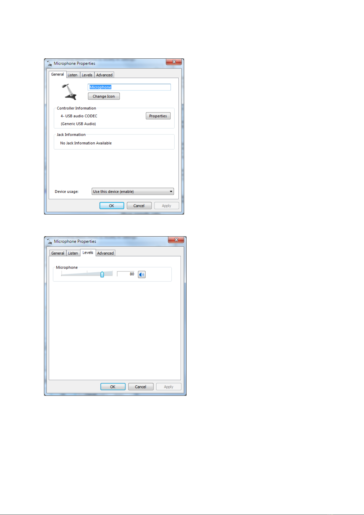
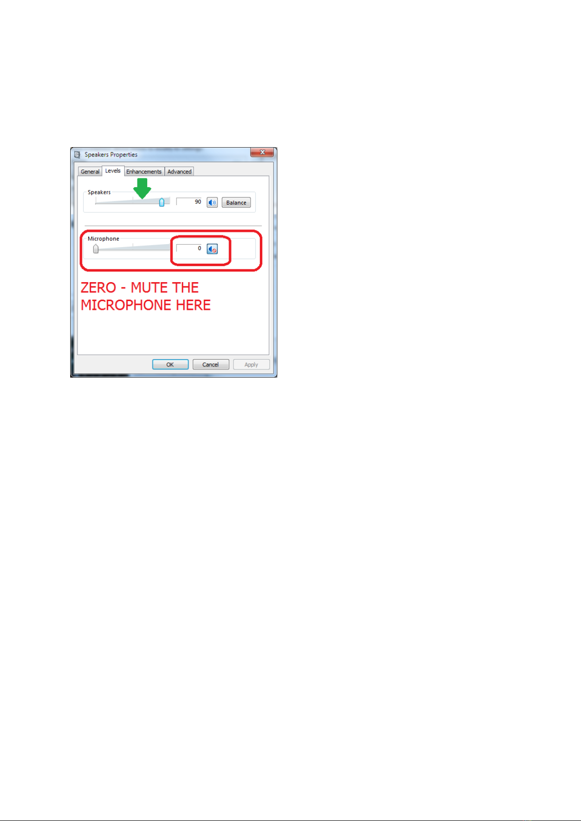
Select the “Levels” Tab;
Adjust the Speakers as appropriate, normally set to 90-100%
IMPORTANT TO MUTE the Microphone here, this is NOT the same microphone used for input. This
microphone is used to sample the output from the speakers and you may not achieve correct results
if you do not mute this input.
DONE
When using DATA interfaces, many users (mistakenly) set the power output on the radio and
overdrive the radio with a strong signal from the DATA interface and end up with a poor TX signal or
high ALC...
An easy way to set and get a good TX signal is as follows;
[a] Set your radio’s power control to maximum.
[b] Adjust the Windows drive level using Windows volume control, adjusting the drive level will set
your radios power output. Aim to adjust the level bearing in mind that 10 or 20 watts is often more
than adequate.

Setting the default soundcard.
You may wish to set your original soundcard as the “default” soundcard and this will prevent
Windows system sounds from activating the interface. This is done via standard Windows
configuration. Open Windows “Volume Mixer”. The contents of the Window will depend on what
software you have running. The first item is the “Device”, this is where your soundcards can be
selected. The button will say “Speakers”, clicking he button will allow you to select the soundcards.
Select YOUR soundcard, then click on the image in t he Applications “System Sounds”, the following
window will open;-

Click on the tab “Playback”;-
Click on the soundcard you wish to use for system sounds then click the button “Set Default”.
System sounds are now configured to be played back through your normal speakers while your DATA
software will use the audio codec.
There are other ways to go through the Windows process to achieve the same results.
Also notice that in the Volume Mixer, you can set the overall audio level for ALL soundcards so be
careful not to inadvertently set this so as to limit your audio levels.

In case of problems
LED switches from GREEN to RED when operating software to TX.
Some radios may go into TX but send no DATA.
Some radios will not go into TX.
[a]
Some radios such as Icom 706 require baud rate to be set at 1200.
This selects the appropriate pin on the 6 pin DATA socket for PTT (1200 rather than 9600).
This does not in any way affect the speed of any DATA transmission it simply selects the pin used for PTT.
[b]
Some radios FT857 etc require radio to be in “DIG mode” which you should define as “USER-U”.
LED does NOT switch GREEN to RED when operating software to TX.
[a]
The soundcard is NOT SELECTED for both INPUT and for OUTPUT.
[b]
The drive level from the PC is too low to activate the interfaces PTT line –increase drive level.
Use the Windows “balance” control if you wish to reduce DATA drive while maintaining a high PTT drive.
One audio channel is used for DATA, the other channel being used for PTT.
[c]
The soundcard is “muted”.
It is not always easy to see if Windows has muted the audio.
The easy way to “un-mute” the soundcard is to view the driver in device manager, right click and remove the driver.
Switch the interface off then back on and Windows will re-install the driver “UN- muted”.
LED rapidly switches between GREEN and RED when operating software to TX.
[a]
The drive level from the PC is too low to activate the interfaces PTT line –increase drive level.
Use the Windows “balance” control if you wish to reduce DATA drive while maintaining a high PTT drive.
One audio channel is used for DATA, the other channel being used for PTT.
NOTE:
When using the YL02A DATA lead your radio will need to be in the correct mode;-
FT-920
[Click for Info ].
FT-990
[Click for Info ].
FT-1000MP
[Click for Info
FT-1000MKV
FT-2000
[Click for Info ]. Alt YL02B.
FT-5000
[Click for Info ]. Alt YL02B.
FT-9000
Kenwood Radio –NO DATA OUT.
No TX audio but led switches to RED (TX).
Do NOT configure your software to activate PTT via the CAT system.
Operating PTT via the CAT system on a Kenwood radio will open the microphone for input and mute the DATA input.

DigiMaster 6 pin mini din socket.
NOTE: This is the “common” connection to all DigiMaster DATA interfaces.
The MiniProSC does not support fsk and so there is no fsk connection.
Table of contents
Other ZLP Electronics Recording Equipment manuals