Zoeller I840 User manual

1
© Copyright 2020 Zoeller®Co. All rights reserved.
Model Number: ______________ Date Code: _______________
Simplex Duplex
Packaged System Field Assembled System
Job Name: ____________________________________________
Distributor: ____________________________________________
Date of Purchase: _________ Zoeller S/O No.: ______________
Contractor: ____________________________________________
Date of Installation: ____________________________________
System Readings During Start-up: Voltage _____ Amps _____
OWNER’S MANUAL
MODELS 840, 841 & 842 SUBMERSIBLE GRINDER UNITS
in the ownership of a Zoeller®submersible wastewater product.
Please read and review this manual before installing the product.
Follow the steps in this manual for a proper start-up. Many items
containedwithin,whenfollowed correctly,will notonly ensurea long
and problem-free life for the pump, but also save time and money
during installation. Reference FM1308 for model 840, FM2445 for
model 842 and FM2180 for model 841 replacement parts. Should
further assistance be necessary please call our Technical Service
Department at 1-800-928-PUMP (7867).
Owner’s Information
Safety Instructions
TO AVOID SERIOUS OR FATAL PERSONAL INJURY OR MAJOR
PROPERTY DAMAGE, READ AND FOLLOW ALL SAFETY
INSTRUCTIONS IN THIS MANUAL AND ON THE PUMP.
THIS MANUAL IS INTENDED TO ASSIST IN THE INSTALLATION AND
OPERATION OF THIS UNIT AND MUST BE KEPT WITH THE PUMP.
This is a SAFETY ALERT SYMBOL.
When you see this symbol on the pump or in the
manual, look for one of the following signal words
and be alert to the potential for personal injury or
property damage.
Warns of hazards that WILL cause serious personal
injury, death or major property damage.
Warns of hazards that CAN cause serious personal
injury, death or major property damage.
Warns of hazards that CAN cause personal injury or
property damage.
INDICATES SPECIAL INSTRUCTIONS WHICH ARE
VERY IMPORTANT AND MUST BE FOLLOWED.
THOROUGHLY REVIEW ALL INSTRUCTIONS AND WARNINGS PRIOR TO
PERFORMING ANY WORK ON THIS PUMP.
MAINTAIN ALL SAFETY DECALS.
PUMPSWITHTHE “US”MARKARE TESTED TOULSTANDARD UL778.CSA
CERTIFIED PUMPS ARE CERTIFIED TO CSA STANDARD C22.2 NO. 108.
CAUTION
Table of Contents
Safety Instructions.......................................................................................1
Limited Warranty and Application...............................................................2
Preinstallation Checklist..............................................................................3
General Information......................................................................................4
Pump Wiring Instructions ............................................................................5
Typical Indoor Prepackaged System ...........................................................6
Indoor Prepackaged Installation Instructions ............................................7
Typical Outdoor Prepackaged System ........................................................8
Outdoor Prepackaged Installation Instructions..........................................9
Operation.....................................................................................................10
Cutter Maintenance....................................................................................11
Service Checklist........................................................................................12
REFER TO WARRANTY ON PAGE 2.
FM2168
0320
Supersedes
0318
NOTICE TO INSTALLER: Instructions must remain with installation.
Congratulations on the purchase of a Zoeller®submersible
grinder pump. Since 1939, the name Zoeller®has represented the
standard for submersible dewatering and sewage pumps. The same
high quality workmanship and easy maintenance design has been
incorporated into this line of heavy-duty submersible grinder pumps.
This Zoeller®pump will provide years of trouble-free service when
installed according to the manufacturer’s recommendations.
This manual incorporates the installation, operation,
maintenance, and service instructions into one document to aid
P/N 019557
Product information presented
here reects conditions at time
of publication. Consult factory
regarding discrepancies or
inconsistencies.
MAIL TO: P.O. BOX 16347 • Louisville, KY 40256-0347
SHIP TO: 3649 Cane Run Road • Louisville, KY 40211-1961
TEL: (502) 778-2731 • 1 (800) 928-PUMP • FAX: (502) 774-3624
Visit our website:
zoellerpumps.com
Register your
Zoeller Pump Company
Product on our website:
http://reg.zoellerpumps.com/

2
© Copyright 2020 Zoeller®Co. All rights reserved.
LIMITED WARRANTY
APPLICATIONS
1. Zoeller Grinder Pumps are designed for grinding and pumping
sanitarysewagefrom submersiblelift stations. Thepumpis intended
to grind and pump reasonable quantities of items normally found
in sanitary sewage applications.
2. Zoeller 840, 841 and 842 Grinder Pumps can be installed in new
applications or as a direct replacement for any grinder application
of like size and capacity. Some rail system retrot kits are available.
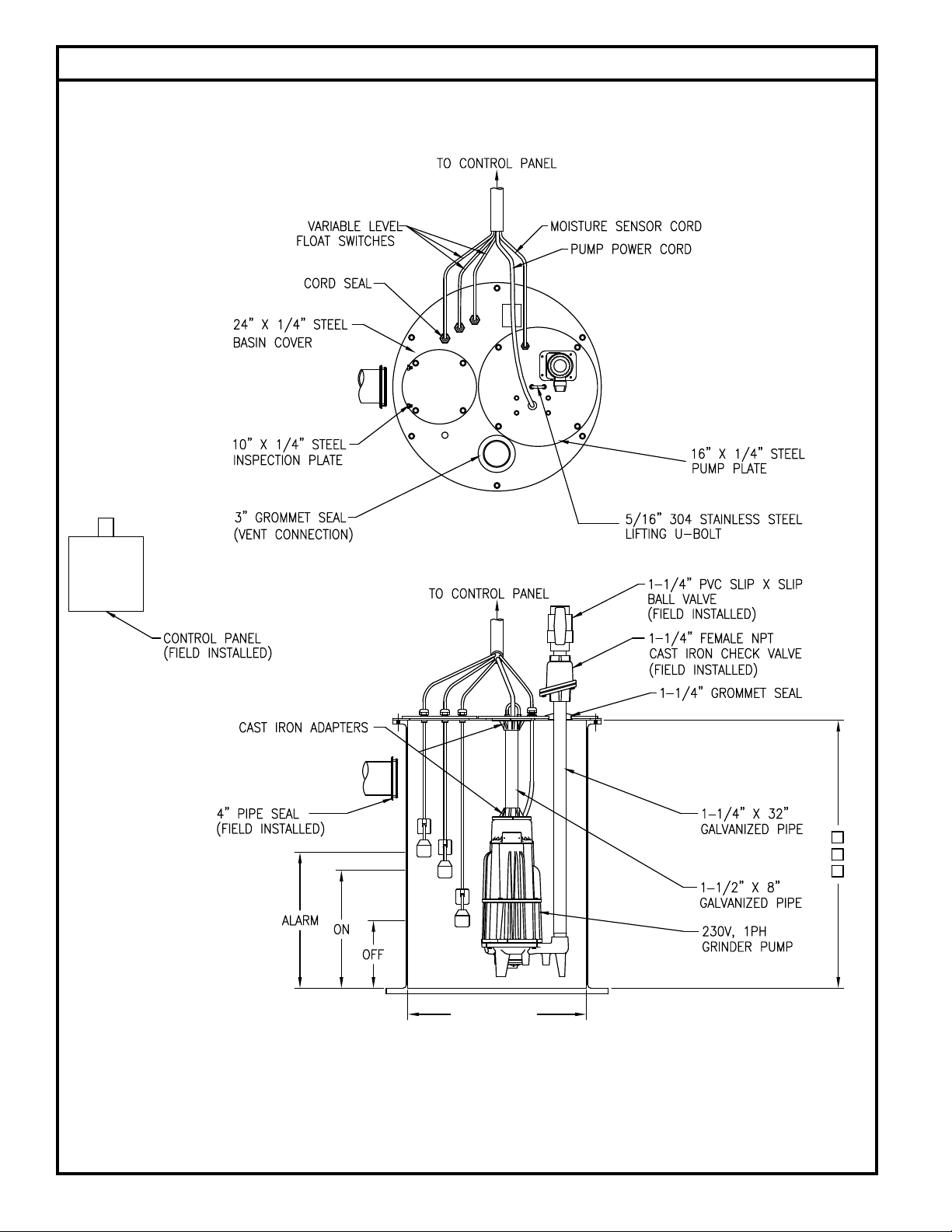
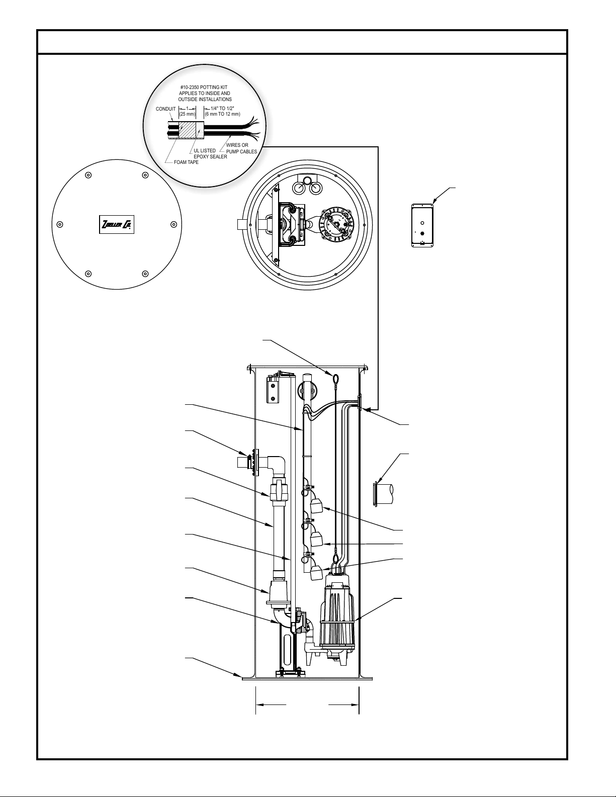
3. The 840, 841 and 842 can be installed in a Prepackaged Job Ready
System or may be used in a Field Assembled basin package. Pages
6 and 8 show a couple of Prepackaged Systems. Field Assembled
Systems are discussed on pages 3 and 4.
4. Zoeller 840, 841 and 842 Grinder Pumps can be retrotted to existing
positive displacement pump installations.
substances, wash towels or feminine sanitary products, etc. in all
applications other than in raw sewage pumping applications. The
warranty set out in the paragraph above is in lieu of all other warranties
expressed or implied; and we do not authorize any representative or other
persontoassumeforusany other liabilityinconnectionwithourproducts.
Contact Manufacturer at, 3649 Cane Run Road, Louisville, Kentucky
40211, Attention: Customer Service Department to obtain any needed
repair or replacement of part(s) or additional information pertaining to
our warranty.
MANUFACTURER EXPRESSLY DISCLAIMS LIABILITY FOR SPECIAL,
CONSEQUENTIAL OR INCIDENTAL DAMAGES OR BREACH OF EXPRESSED
OR IMPLIED WARRANTY; AND ANY IMPLIED WARRANTY OF FITNESS FOR
A PARTICULAR PURPOSE AND OF MERCHANTABILITY SHALL BE LIMITED
TO THE DURATION OF THE EXPRESSED WARRANTY.
Somestatesdonotallowlimitationsonthedurationofanimpliedwarranty,
so the above limitation may not apply to you. Some states do not allow
the exclusion or limitation of incidental or consequential damages, so
the above limitation or exclusion may not apply to you.
This warranty gives you specic legal rights and you may also have
other rights which vary from state to state.
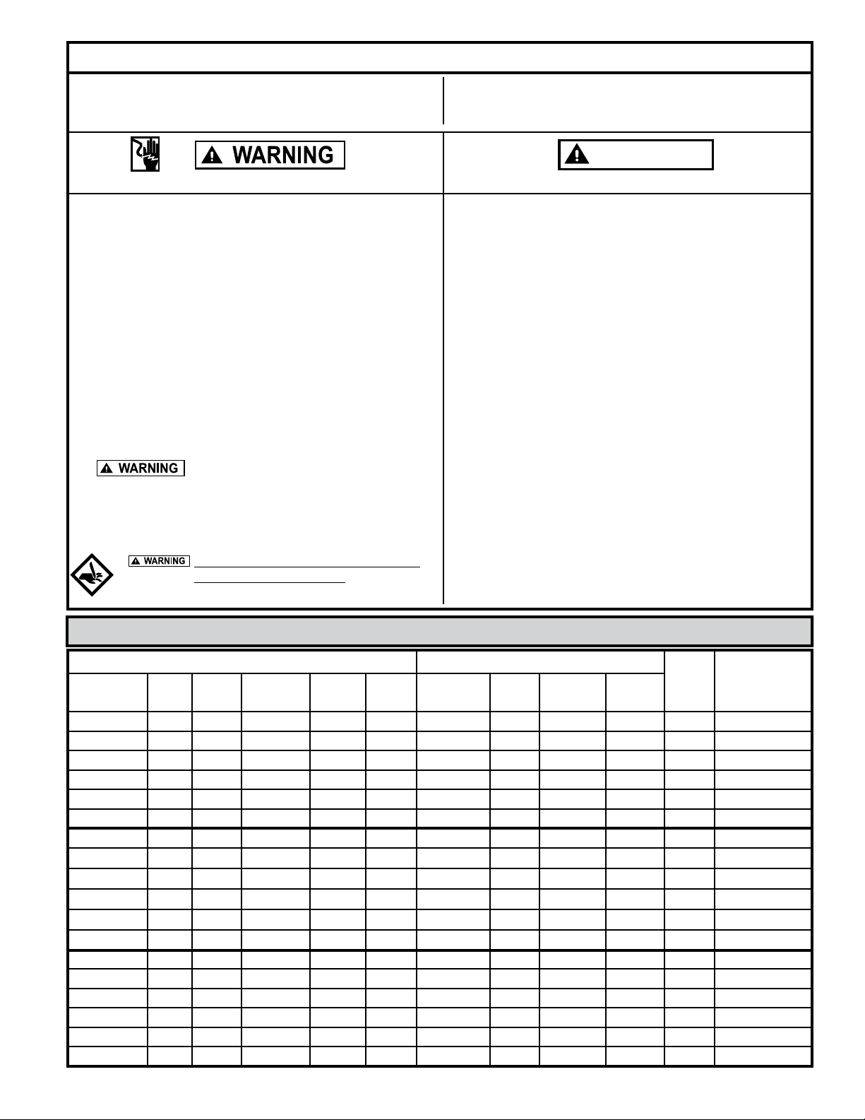
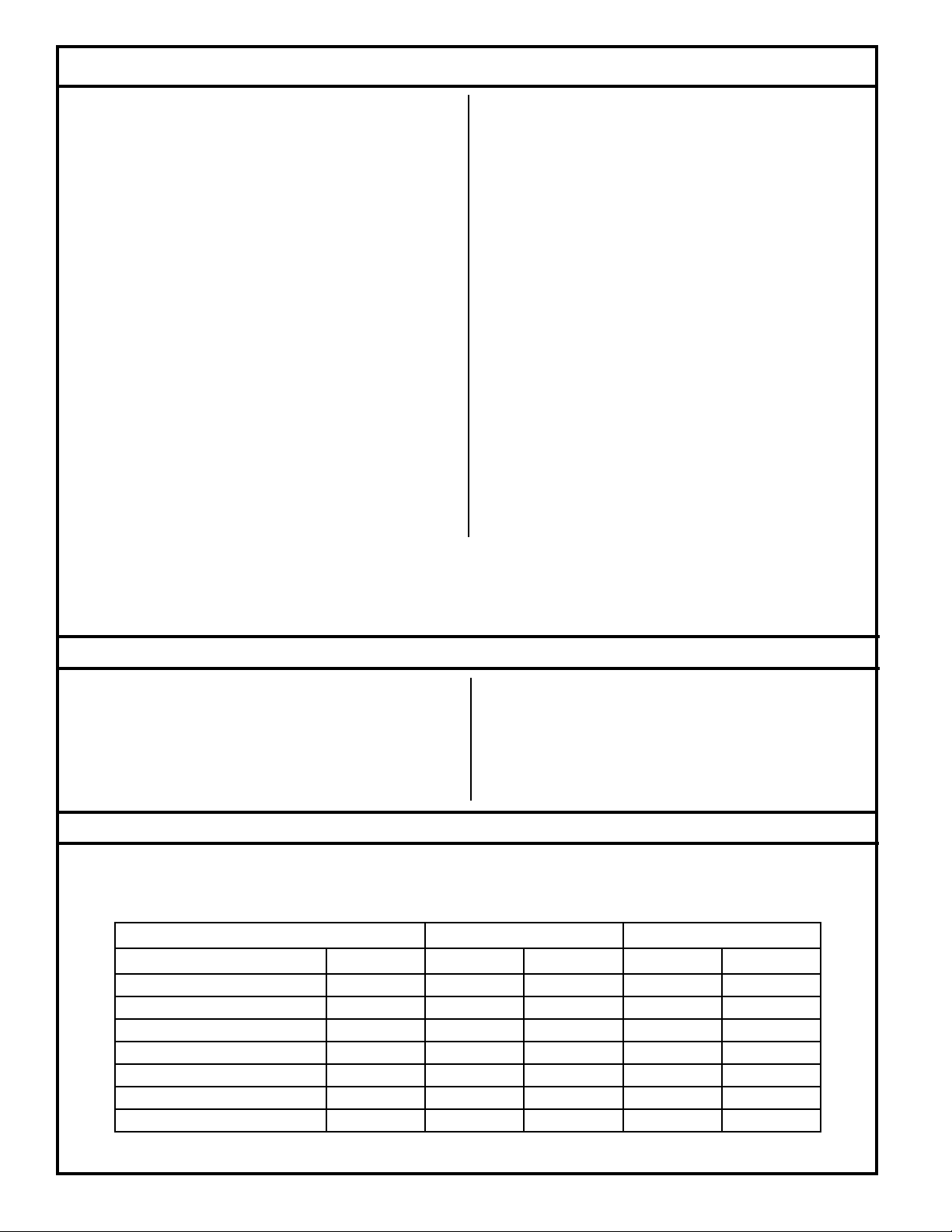
*Zoeller Company does not recommend a simplex station on anything over two homes in order to maintain continuous service during unusual
conditions.
Recommended Limits of Application 800 Series Grinder Pumps
These recommended application limits are for pump stations pumping to a gravity main. Low-pressure pipe systems should be designed with a
pump located at each house. For applications where a lift station would handle between 15 and 60 homes, consider the 71 Series grinder pump,
which is available through Zoeller Engineered Products. For applications where a lift station would handle more than 60 homes, a solids handling
type pump should be considered.
Manufacturer warrants, to the purchaser and subsequent owner during
thewarrantyperiod,every newproducttobefree fromdefectsinmaterial
and workmanship under normal use and service, when properly used
and maintained, for a period of one year from date of purchase by the
end user, or 18 months from date of original manufacture of the product,
whichever comes rst. Parts that fail within the warranty period, one
year from date of purchase by the end user, or 18 months from the date
of original manufacture of the product, whichever comes rst, that
inspections determine to be defective in material or workmanship, will
be repaired, replaced or remanufactured at Manufacturer's option,
provided however, that by so doing we will not be obligated to replace
an entire assembly, the entire mechanism or the complete unit. No
allowance will be made for shipping charges, damages, labor or other
charges that may occur due to product failure, repair or replacement.
This warranty does not apply to and there shall be no warranty for any
materialorproduct thathasbeen disassembledwithoutprior approvalof
Manufacturer, subjected to misuse, misapplication, neglect, alteration,
accident or act of nature; that has not been installed, operated or
maintained in accordance with Manufacturer's installation instructions;
that has been exposed to outside substances including but not limited to
thefollowing: sand,gravel,cement,mud, tar, hydrocarbons,hydrocarbon
derivatives (oil, gasoline, solvents, etc.), or other abrasive or corrosive
Simplex Station Duplex Station
Model HP Homes GPD Homes GPD
810 Progressing Cavity Grinder 1 1 400 2 800
815 Progressing Cavity Grinder 2 1 400 2 800
820 2 1 400 2 800
840 w/o Reversing Control 2 2* 800 10 4,000
840 w/ Reversing Control 2 2* 800 15 6,000
841 2 2* 800 10 4,000
842 2 2* 800 10 4,000

3
© Copyright 2020 Zoeller®Co. All rights reserved.
Preinstallation Checklist
1. Inspect your grinder pump. If the unit has been damaged in shipment,
contact your dealer before installing. Do Not remove the test plug in
the cover nor the motor housing.
2. Carefully read all literature to familiarize yourself with details regarding
installation and use. Retain materials for future reference.
1. Make sure pump connection contains a ground terminal. The power cord
on all Zoeller Grinder Pumps contains a green conductor for grounding
to help protect you against the possibility of electric shock.
2. Make certain the electrical service is within reach of the power supply cord.
3. Makesureanypanelsandbranchcircuitsareequippedwithpropersizefuses
and circuit breakers. An independent power circuit is recommended,
sized according to the National Electrical Code, for the current shown
on the grinder pump nameplate.
4. For your protection, always disconnect the power source to the grinder
pump before handling. All grinder pumps must be properly grounded
and wired in accordance with the “National Electrical Codes” and all
local codes and ordinances.
5. Installation of electrical hardware and checking of control panels
and circuits should be performed by a qualied licensed electrician.
6. Risk of electrical shock - These pumps have not been investigated for
use in swimming pool areas.
7. Prop65 Warning for California residents:
: Cancer and Reproductive Harm-
www.P65Warning.ca.gov.
1. Make sure the power source is capable of handling the electrical
requirements of the grinder pump, as indicated on the nameplate.
2. A disconnect switch should be installed ahead of the pump.
3. The Grinder pumps are operated by control panels with variable level
oat control switches. It is the responsibility of the installing party to
see that oat control switches will not hang up on the grinder pump
or other pit peculiarities and are secured so that the grinder pump
will shut off. It is recommended to use rigid pipe and ttings and
the pit be 24" in diameter for simplex systems and 36" in diameter for
duplex systems or larger.
4. Grinder installations should be checked yearly for debris and/or build
up which may interfere with the “ON” or “OFF” positions of variable
level oat control switches. Repair and service, other than cutter
assembly maintenance, should be performed by Zoeller authorized
service stations only.
5. Maximum operating temperature must not exceed 130 °F,
(54 °C).
6. Pumpandfloatswitchelectricalconnectionsmustbepermanently installed,
operational and protected from submergence.
7. Junctionboxconduit must beinstalledwith watertightconnection. Zoeller
junction boxes include a UL Listed potting kit for sealing the conduit.
Failure to properly install this sealant material could void warranty.
Do not attempt to turn star cutter located on
bottom of the unit with fingers. Use a wrench
when checking or removing star cutter.
SEE BELOW FOR LIST OF WARNINGS
CAUTION
SEE BELOW FOR LIST OF CAUTIONS
Electrical Data
Amps KVA
Code
Winding
Resistance
Line-to-Line
Model HP RPM Voltage Phase Hertz Full Load In Air Shut Off Locked
Rotor
I840 2 3450 200 1 60 20.0 6.6 12.1 60 H 1.0 / 1.5
E840 2 3450 230 1 60 17.2 4.0 10.9 56 F 1.3 / 4.0
J840 2 3450 200 3 60 12.3 3.7 7.7 54 L 1.9
F840 2 3450 230 3 60 10.8 3.3 6.9 42 K 2.4
G840 2 3450 460 3 60 5.5 1.6 3.5 21 K 9.7
BA840 2 3450 575 3 60 4.5 1.0 2.5 11 F 15.3
I842 2 3450 200 1 60 20.0 6.6 12.1 60 H 1.0 / 1.5
E842 2 3450 230 1 60 17.2 4.0 10.9 56 F 1.3 / 4.0
J842 2 3450 200 3 60 12.3 3.7 7.7 54 L 1.9
F842 2 3450 230 3 60 10.8 3.3 6.9 42 K 2.4
G842 2 3450 460 3 60 5.5 1.6 3.5 21 K 9.7
BA842 2 3450 575 3 60 4.5 1.0 2.5 11 F 15.3
I841 2 3450 200 1 60 20.0 6.6 12.1 60 H 1.0 / 1.5
E841 2 3450 230 1 60 17.2 4.0 10.9 56 F 1.3 / 4.0
J841 2 3450 200 3 60 12.3 3.7 7.7 54 L 1.9
F841 2 3450 230 3 60 10.8 3.3 6.9 42 K 2.4
G841 2 3450 460 3 60 5.5 1.6 3.5 21 K 9.7
BA841 2 3450 575 3 60 4.5 1.0 2.5 11 F 15.3

4
© Copyright 2020 Zoeller®Co. All rights reserved.
General Information
GRINDER PUMP DESCRIPTION
1. Pumps are constructed of cast iron protected with powder coated
epoxy for long life when pumping sewage in submersible applications.
The cutter assembly is comprised of stainless steel components
hardened to a value of 55-60 on the Rockwell C scale; a star shaped
cutter and a precision ground at disk. Cutting action takes place
with the rotation of the star cutter at 3450 RPM against the stationary
cutter plate (see page 11).
2. The cutter mechanism on the model 840 is bidirectional, enabling it
to cut in either direction. A control panel with the reversing feature
will alternate the pump’s rotational direction with each duty cycle.
The cutter mechanism on the model 841 and 842 is single directional.
3. Pump motors are available in single and three phase design. Single
phase motors require a Zoeller approved starting relay, starting
capacitor and a run capacitor, which are mounted in a control panel
(ref. page 8).
4. The 840, 841 and 842 Grinder Pumps are dual seal and have seal leak
probes. Single phase units have an internal thermal overload. Three
phase pumps have a thermal sensor.
5. Three phase pumps require overload protection in the control panel.
6. A Grinder Pump is an intermittent duty pump designed for pumping
sanitary sewage. It is not a dewatering or trash pump.
FIELD ASSEMBLED INSTALLATION
1. Installation and piping instructions are included with the control
panel, rail system and basin instructions. If pump is being retrotted
to an existing rail system, accessory parts may be required. Consult
the factory and advise make and model of rail system being used.
2. Refer to the appropriate Indoor/Outdoor prepackaged instructions
on pages 6-9 for more information on system installation.
3. All electrical connections including pump to control box and
power supply to control panels must comply with the “National
Electrical Code” and applicable local codes. Conduit and
panel enclosure openings must have a gas and watertight
seal. Installation of electrical panels, conduit and connections
should be made by a qualied licensed electrician. A UL Listed
potting kit, P/N 10-2350, is available from Zoeller Company.
4. A properly sized disconnect switch, supplied by others, shall be
installed on the service side of the pump and control panel.
5. When installing a pump with a check valve, or a rail system with
a check valve, you must give the pump case time to ll to help
prevent air lock when lowering the unit into the liquid. The pump
case has an air vent located behind the discharge. This air vent is
across the pump housing mounting surface and must be cleaned
before each reinstall. An extra air vent hole (3/16") may be drilled
in discharge pipe below the check valve to help prevent air lock.
This drilled hole must be cleaned before each reinstall. After the
pump is installed, run the unit submerged to assure the pump case
is lled (Water should come out of 3/16" diameter hole).
FIGURE 1.
016532
HEAD CAPACITY CURVE
MODEL 840/841/842
0 40 80 120 160 200 240
70605040302010
0
10
4
8
12
16
20
130
70
60
50
40
30
20
FLOW PER MINUTE
GALLONS
LITERS
TOTAL DYNAMIC HEAD
80
90
28
24
METERS
FEET
100
110
120
32
36
840 841842
TOTAL DYNAMIC HEAD/FLOW
PER MINUTE
SEWAGE
MODEL
Feet
Shut-off Head:
840
Meters Gal. Liters
5
10
20
30 9.1
6.1
3.0
1.5
44
45
167
170
104 ft (31.7 m)
60
50
40
90
80
70
110
100
120
12.2
15.2
18.3
21.3
24.4
27.4
30.5
33.5
36.6
42
36
30 114
136
159
23
16
10 38
61
87
3
--
-- --
--
11
125 ft (38.1 m)
841
Gal. Liters
45 170
45 170
125 ft (38.1 m)
9525
13
4
20 76
49
15
34
32
29
34
34
34
34
129
121
110
129
129
129
129
842
Gal.
34
34
129
129
Liters
52
49 185
197
43
36
28 106
136
163
19
11
415
42
72
54 204
54 204
54 204
54 204
54 204

5
© Copyright 2020 Zoeller®Co. All rights reserved.
MOISTURE SENSOR
L1 L2 L3
POWER CABLE
CONTACTOR T1 T2 T3
208V/230/460V
3ø POWER
SENSOR CABLE
THERMAL SENSOR
ORANGE
BLACK
RED
WHITE
GREEN
(18-4 OR 18-5)
BEFORE 6/2000
NORMALLY OPEN
330K OHMS RESISTANCE
NORMALLY CLOSED
Pump Wiring Instructions
FOR YOUR PROTECTION, ALWAYS DISCONNECT THE PUMP FROM ITS POWER SOURCE BEFORE HANDLING.
All electrical connections must be wired and grounded in accordance with the National Electrical Code and all applicable
local codes and ordinances.
“Risk of electrical shock” Do not remove the power supply cord and strain relief or connect conduit directly to pump.
Installation and checking of electrical circuits and hardware should be performed by a qualied licensed electrician.
FIGURE 2. LEAD IDENTIFICATION WIRING DIAGRAM
SINGLE PHASE-2HP
MODEL 840
SK1367 009048
THREE PHASE
MODELS 840, 841 & 842
FIGURE 4.
FIGURE 3.
L1
START RELAY
START CAPACITOR
GREEN
RED
WHITE
BLACK
BLUE
ORANGE
MOISTURE
SENSOR
TERMINALS
WHITE
BLACK
14-618-2
REVERSE MOTOR ROTATION BY INTERCHANGING
ORANGE WIRE WITH RED WIRE.
L2
RUN CAPACITOR
GROUND SCREW
2
1
5
COMPONENT LAYOUT
PUMP
START RELAY
START CAPACITOR
RUN CAPACITOR
RED
WHITE
ORANGE
BLACK
MAIN START
PROTECTOR
BLACK
WHITE
L1 L2
T2
T1
230V AC
OR
208V AC
CONTACTOR
BLUE
2
1
5
SINGLE PHASE
MODELS 841 & 842
LEAD IDENTIFICATION WIRING DIAGRAM
WIRING DIAGRAMLEAD IDENTIFICATION
14-4
18-4
L1 L2 L3
T1 T2 T3
BLACK
RED
GREEN
POWER
CORD
MAGNETIC
STARTER
CORD
SENSOR
WHITE
BLACK
ORANGE
RED
WHITE
MOISTURE
SENSOR
TERMINALS
SENSOR
TERMINALS
TEMPERATURE
OR
18-5
GREEN
START RELAY
START CAPACITOR
MOISTURE
SENSOR
TERMINALS
BLACK
WHITE
L1 L2
RUN CAPACITOR
GROUND SCREW
BLACK
WHITE
RED
GREEN
18-2 14-4
2
1
5
SK1368 SK1370
SK2399
RUN CAPACITOR START CAPACITOR
T1
BLACK
WHITE
T2
START RELAY
L1 L2
208V AC
OR
230V AC
CONTACTOR
YELLOW
MAIN WINDING
AUXILIARY WINDING
OVERLOAD
BLUE
5
5
ORANGE
WHITE
RED
BLACK
43
43
21
21
GREEN
WHITE
BLACK
RED
MOTOR
CHAMBER
COVER
CHAMBER
2
1
5
SK2400

6
© Copyright 2020 Zoeller®Co. All rights reserved.
Indoor Prepackaged System
FIGURE 5.
All installations must comply with all applicable electrical and plumbing codes, including but not limited to the
National Electrical Code, local, regional and/or state plumbing codes, etc.
SK1695
36”
48”
60”
24” NOMINAL

7
© Copyright 2020 Zoeller®Co. All rights reserved.
Indoor Prepackaged System Installation Instructions
This set of instructions is for factory prepackaged indoor systems only. If your system is a eld assembled indoor system, use
these instructions as a guideline. If your system is an outdoor system then go to the next section in this manual that covers outdoor systems.
1. Indoor grinder pump systems are for installing at grade in an indoor
application only. If you will be installing this system outside next to
theresidencethen you willneedan outdoorsystem. DONOTINSTALL
THE INDOOR SYSTEM OUTDOORS.
2. Review the drawing in Fig. 5 on page 6 and the actual system to
become familiar with the components in the grinder pump system.
Review where the unit will be installed. Determine where the power
feed, inlet pipe, discharge pipe and vent will be located.
3. Remove the unit from the packing. Indoor prepackaged systems
are preassembled at the Zoeller Company and require a minimum of
eld assembly work. All work inside the basin can be performed via
the inspection port. There should be no reason to remove the cover
from the basin. Pump and oat switches are already set inside the
basin.
4. Remove the inspection plate from the cover. All oats are set and
tethered for proper operation from the factory. Verify that where the
oat switches are set will work for your application. Verifying that the
oat switches are set properly and will not hang up inside the basin
is the responsibility of the installing contractor. Float switches are
tied in place for shipping purposes. Cut the cable tie around each
oat switch bulb or the unit will not operate properly.
5. Dig a hole for the basin. The basin should be located in a very low
trafc area within 15' of the power disconnect. The hole should be at
least 8" larger in diameter than the basin in order to leave 4" of backll
all the way around the perimeter. A minimum of 4" of compacted
subbase is also required. Backll and subbase should be 1/8" to
3/4" pea gravel or 1/8" to 1/2" crushed stone. Also reference the basin
installation instructions included with the unit.
6. The 4” inlet hub should be located between the top lip of the basin
and the alarm oat “on” level with a minimum distance of 10 inches
between the oor of the basin and hub. Determine the location of
the inlet hub based upon your inlet pipe arrangement. The inlet
hub must be used with 4” pipe. It is best to install the inlet on the
side of the basin opposite the oat switches. Most systems are
supplied with a eld installed 4" pipe seal inlet tting. This inlet
tting is installed in the basin's side-wall in a 5" hole drilled with a
hole saw at a location lining up with the inlet pipe.
7. Set the basin in the hole and connect the 4" inlet pipe to the inlet hub
using the rubber insert. Backll around the basin with specied
media. Care should be taken not to damage components or leave
voids when backlling. Finish grade of oor should be poured in
place around the top 6" of the basin assembly.
8. Connect the discharge pipe, valves and vent according to all
applicable National, State and Local plumbing codes.
9. Mount the control panel on the wall within 15' of the system.
Connect the oat switch and pump cords.
10. Clean any debris out of the basin. Fill the basin with water and
check the system for proper operation.
11. Record system start-up data for future reference.
12. Seal and secure the inspection plate to the lid using the proper
bolts and sealant. Pouring concrete around the system can now
be completed.

8
© Copyright 2020 Zoeller®Co. All rights reserved.
Typical Outdoor Grinder Pumping System Installation
All installations must comply with all applicable electrical and plumbing codes, including but not limited to the National
Electrical Code, local, regional and/or state plumbing codes, etc.
FIGURE 3.
R
LOUISVILLE, KY
SILENCE
INPUT1
POWER
4" PIPE SEAL
(FIELD INSTALLED)
2" PIPE SEAL
(FIELD INSTALLED)
24" MIN.
FIBERGLASS AFD
1.25-2" Z-RAIL
2" CAST IRON CHECK VALVE
3/4" GUIDE RAILS
2" SCH. 80 BALL VALVE
2" FLEX BOOT FITTING
(LOCATION VARIES
WITH BASIN DEPTH)
FLOAT TREE ASSEMBLY
2HP GRINDER PUMP
2" PVC SCH. 80 PLBG.
1/8" 302 STAINLESS STEEL
LIFTING CABLE
ALARM
ON
OFF
SOLID FIBERGLASS COVER
HIGH WATER ALARM
OR SIMPLEX
CONTROL PANEL
(FIELD INSTALLED)
ALARM FLOAT SWITCH MUST OPERATE OFF LOW
VOLTAGE TO BE USED WITH QWIK BOX.
SK3110
FOAM TAPE
UL LISTED
EPOXY SEALER
#10-2350 POTTING KIT
APPLIES TO INSIDE AND
OUTSIDE INSTALLATIONS
CONDUIT 1
WIRES OR
PUMP CABLES
1/4" TO 1/2"
(25 mm) (6 mm TO 12 mm)
SK1661
LOCATION VARIES WITH BASIN DEPTH

9
© Copyright 2020 Zoeller®Co. All rights reserved.
Outdoor Prepackaged System Installation Instructions
1. Review the drawing in Fig. 3 on page 8 and the actual system to
becomefamiliarwiththecomponentsinthepackagedgrinderpump
system. Review where the unit will be installed. Determine where
the power feed, inlet pipe, and discharge pipe will be located.
2. Remove the unit from packing. Prepackaged outdoor systems are
preassembled at the Zoeller Company and require a minimum of
eld assembly work. Float switches are set and tethered for proper
operation from the Factory. Systems using an automatic unit, WD
or WH series, have an integral “on/off” oat switch. See Fig. 4
on page 5 for adjustment instructions. The alarm switch should
be located 3” above the pump “on” level. Three oat systems
used with a control panel are placed at 27”, 24”, and 15” from the
bottom of the basin. Four oat systems used with a control panel
are placed at 33”, 27”, 24”, and 15” from the bottom of the basin.
If the invert location is at or below the level of the oat switches,
contact the factory.
3. Float switches are tied in place for shipping purposes on all model
prepackaged systems. Cut the cable tie around each oat switch
bulb or the unit will not operate properly. Verify that where the
oat switches are set will work for your application. Verifying
that the float switches are set properly and will not hang up
inside the basin is the responsibility of the installing contractor.
4. Dig a hole for the basin. The hole should be at least 24” larger in
diameter than the basin diameter to provide 12” of backll all around
and deep enough to provide either 12” of compacted backll or 6”
when a concrete pad is required. Note: Care must be taken when
excavating in order to avoid underground utilities and disturbance of
existing structure foundations. The hole should be located at least ten
feet from adjacent structures. Additional distance may be required to
sufficiently locate the basin outside of the loading area of the adjacent
structures.
5. Determine the location of the inlet hub based upon your inlet pipe
arrangement. The inlet hub must be used with 4” pipe. It is best to
install the inlet on the side of the basin opposite the oat switches.
Most systems are supplied with a eld installed 4" pipe seal inlet
tting. This inlet tting is installed in the basin's side-wall in a 5"
hole drilled with a hole saw at a location lining up with the inlet
pipe.
6. The bottom of the excavation can now be properly backlled,
compacted and leveled. Set basin in hole. Ensure the removable
cover extends above the nished grade line and the grade slopes
away from the unit. Backll and subbase should be 1/8” –3/4” pea
gravel or 1/8” –1/2” crushed stone. (Reference basin installation
instructions included with unit.) Connect the 4” inlet pipe to the
inlet hub.
7. Pouring a concrete anchor around system can now be completed.
Basin should be lled with water when pouring concrete to minimize
movement of the system. Backll around basin with specied media.
Careshouldbe used toavoiddamaging componentsorleaving voids
when back lling. Refer to Basin installation reference guide on
more specic requirements.
8. PVC or HDPE discharge piping is connected to the 2” threaded
tting located in the basin sidewall. Support discharge piping with
sufcient backll.
9. Connect liftcabletotop of pump. Lowerthepumpinto basinensuring
the discharge pipe bracket slides into the disconnect tting.
10. Note: Thegrinder basinisasewage holdingtank. Ventconnection should
be installed in accordance with all national, state and local plumbing
codes.
11. Dig atrenchforthe electricalconduit. Theconduitshould belocated
below the frost line. Follow all applicable electrical codes.
12. If using a junction box, connect the electrical conduit and wiring
accordingtoinstructionsincluded inthismanualandwiring diagram
in box. If a potting kit is provided with the junction box, follow the
instructions for sealing the conduit connection to the junction box.
If a potting kit is not provided, the conduit connection to the junction
box must be sealed.
13. Mount the control panel within sight of the system. Connect
oat switches and pump cords according to the “Pump Wiring
Instructions” found later in this manual and located inside the panel
enclosure.
14. Remove any debris from the basin. Using clean water, check the
system for proper operation.
15. Seal and secure the lid using the proper bolts and sealant when
using a lid without a formed gasket.
16. Test system for leaks and proper pump operation.
17. Record system start up data for future reference.
This set of instructions is for factory prepackaged outdoor grinder systems only. If this is a eld assembled outdoor system
you can use these instructions as a guideline. If this is an indoor system then go back to pages 6-7 in this manual that covers indoor systems.

10
© Copyright 2020 Zoeller®Co. All rights reserved.
Operation
GENERAL
Zoeller pumps are lubricated and tested at the factory prior to shipment
and require minimum pre-start-up maintenance.
Maximum operating temperature of pump liquid for grinder pumps must
not exceed 130 °F (54 °C).
These units are designed for intermittent duty sanitary sewage
applications. If pump is used to dewater areas or pump liquids with
heavy or abrasive materials, the warranty will be voided.
NAMEPLATE DATA
The nameplate, located on the side of the pump, indicates specic
information about the construction of the pump. The model number
and date code information should be recorded on the front page in the
“Owner’s Information” section of this manual.
SHORT TERM STORAGE
Donotinstallpumpuntilelectricalpowerisavailableandsystemis operational.
When not in use, the pump should be stored and the following is advised:
• Store pumpinside wheneverpossibleorcoverwithsometypeofprotective
covering.
• Tape or seal in plastic bag the terminal ends of wire leads.
• Spray coat unpainted surfaces with rust inhibiting oil.
• The impeller should be rotated every six months in order to keep the
seals lubricated and not develop a permanent set.
If panel is to be stored, the following is advised:
• Store the panel inside whenever possible and leave in the shipping
box.
• All openings shall be sealed.
• Store in an upright position.
• Do not stack anything on top of panel.
START-UP PROCEDURE
Before placing the equipment into operation the following should be
checked:
• Clean pit.
• Pump, oat switches, electrical cables and junction box are dry and
properly installed.
• Electrical boxes dry, sealed and securely installed.
• Floats positioned properly.
• Discharge valves open.
• 3/16" vent hole drilled in pipe between check valve and pump.
Once the above has been veried proceed with the following checks:
• Pump power cables and control oats properly installed and voltage
veried.
• Conduit connections to panel and junction box are properly sealed.
• After installing the pump into the containment area, with adequate
submergence, open the discharge valve fully. Start the unit using
manual controls. If ow is appreciably less than rated performance,
pump may be air locked. To expel trapped air, jog the unit several
times, using the manual controls.
• Have a qualied electrician take voltage and current measurements
with the pump running. Record these readings in the space provided
inthe “Owner’sInformation” sectionon page1 ofthis manualfor future
reference.
ADJUSTMENT PROCEDURE
Pumps: No adjustments are required.
Floats: Refer to the system drawing or to the panel wiring schematic
for the desired location of each oat switch setting.
Valves: Discharge valves should be placed in the fully open position.
Systems should not be operated for extended periods of time
with the discharge valves partially closed due to damaging
the valve.
SHUTDOWN PROCEDURES
If a system is shutdown for more than six months, the following is
recommended:
Pumps: If pit is to remain dry, then the pump can remain in the pit.
With the pump in the pit, it should be operated for ve minutes
once every three months. If the pit is to remain wet, the pump
should be removed and stored as noted above.
Panels: The panel should have all openings sealed to prevent moisture
and dust from entering the enclosure. Prior to restarting system,
the panel should be inspected for presence of moisture and any
loose connections.
Valves: Consult thevalve/actuatorsupplierfor information concerning
these systems components.

11
© Copyright 2020 Zoeller®Co. All rights reserved.
Cutter Maintenance
To remove star cutter: Remove guard ring then heat the
center bolt to 350 °F to loosen Loctite® thread sealant.
Grind the Star Cutter and Disc seen here to a 32 micronish.
Surfaces must be at to within 0.001" T.I.R. Gap must be between
0.004" and 0.008" on these parts.
1. Allpowercircuitsmustbedisconnectedandlockedoutbeforeanyattempts
are made at servicing. The star cutter and disc can be removed and
sharpened by grinding the cutting faces. Both star cutter and disc
must be removed from the pump. Removal of these parts can be
accomplished in the eld by removing pump from the sump and
positioning horizontally to access the intake of the pump. If seals
or other repairs are required, the pump must be totally removed
and serviced in a shop by a qualied pump technician or authorized
service center.
2. Remove the three countersunk screws on the plastic guard ring
and remove the ring.
3. Thoroughly clean the star cutter and disc assembly. Tilt pump
back to the vertical position to make certain the end play has
been removed. Check and record the clearance between the star
cutter and disc with a feeler gage. The correct running clearance
is between 0.004" and 0.008".
4. With pump in horizontal position, heat the hex head bolt in the center
of the star cutter with a propane torch. The bolt must be heated to
350 °F to soften the thread lock sealer on the bolt for ease of removal.
Remove the bolt by turning in a counterclockwise rotation. It will
be necessary to use a wood block to prevent the star cutter from
turning while removing the bolt. Pull star cutter from the shaft and
remove the spacer shims located behind the star cutter.
5. Remove the three cap screws holding the disc and remove disc
from the pump.
6. The disc and star cutter can be replaced with new service parts or
resurfaced by grinding. Resurfacing is accomplished by surface
grinding both disc and star cutter to a 32 micro nish. Do not attempt
grinding in the eld. Send parts to a qualied machine shop or
return to the factory for repair. The disc, star cutter and shims are
a matched set. Keep parts together. Measure disc before and after
resurfacing with micrometer and record measurements.
7. After resurfacing, the disc and star cutter must be at within 0.001".
If the disc has been surface ground, it will be necessary to remove
shims to compensate for the material removed from the disc. As a
starting point, remove shims of the same thickness as the amount
machinedfromthecutterdisc(step6above). Finalrunningclearance
must be between 0.004" and 0.008". Be sure pump is in vertical
position and all end play has been removed before measuring.
8. Clean bottom of pump where disc is located and replace disc and
retainer screws. Torque to 63-67 in-lbs. Replace star cutter with
the correct shims. Install washer and torque hex head bolt to 71-75
in-lbs. apply Loctite 262 thread-lock sealant or equal to bolt threads
prior to insertion. Check running clearance with pump in vertical
position to remove end play. Clearance must be between 0.004" and
0.008" to obtain efcient grinding when pump is put back in service.
9. Replace plastic guard ring and its three screws.
10. Check the oil in the motor housing before reinstalling. Contact the
factory if the oil has a milky appearance or burnt smell. The level
should be even with the ll plug when pump is in the upright position.
Add oil if required. Use insulating oil supplied by the factory.
FIGURE 7.
(Model 840 components shown)

12
© Copyright 2020 Zoeller®Co. All rights reserved.
General Maintenance
Repair and service should be performed by a Zoeller Pump
Company Authorized Service Station only.
SAFETY PROCEDURES
Foryourprotection,alwaysdisconnect pump and panel
from its power source before handling.
Never enter the basin until it has been properly vented
and tested. Any person entering a basin should be wearing a harness
with safety rope extending to the surface so that they can be pulled out
in case of asphyxiation. Sewage water gives off methane and hydrogen sulde
gases, both of which can be highly poisonous.
Installationandcheckingofelectrical circuits and hardwareshouldbeperformed
by a qualied electrician.
Pump is never to be lifted by power cord.
Unitmust becleanedanddisinfected, insidethepumping
chamber and all exterior surfaces, prior to servicing.
GENERAL SYSTEM INSPECTION
Before the system is placed into operation, it should be inspected by a qualied
technician.
Wiring and grounding must be in accordance with the
National Electrical Code and all applicable local codes and ordinances.
LUBRICATION PROCEDURES
No lubrication is required.
If pumps are to be stored for more than six months, refer to short term storage
procedure in the Operation section.
PREVENTIVE MAINTENANCE
Preventive maintenance is recommended to ensure a long service life from the
product. Provided is a suggested maintenance schedule.
Every six months:
• Inspect and test system for proper operation.
• Check for proper and unobstructed oat operation.
• Listen for proper check valve operation.
Every 5 years or 10,000 hours of operation:
• Remove pump, inspect and service using a Zoeller rebuild kit.
• Flush and clean basin.
DOUBLE SEAL PUMPS
Double seal pumps offer extra protection when these pumps are supplied with
optionalmoisturesensors,check thecontrolpanel'ssealfailurelight for awarning.
Whenever the seal leak is activated, it's indicating that moisture is present, and
the pump should be removed and serviced in order to avoid damage to the motor.
Service Checklist
Electrical precautions. Before servicing a grinder pump, always shut off the main power circuit. Make sure you are wearing
insulated protective sole shoes and not standing in water. Under ooded conditions, contact your local electric company or a qualied
licensed electrician for disconnecting electrical service to the pump prior to removal.
Grinder pumps contain oil which becomes pressurized and hot under operating conditions. Allow 2-1/2 hours after shut
down before servicing pump.
Common Causes
Blownpanelorcircuitbreaker fuse,lowvoltage,thermaloverloadopen,defective
capacitor circuit, cutter or impeller clogged, oat switch held down or defective,
incorrect wiring in control panel, water in cap assembly.
Incorrect voltage, impeller or cutter blocked, negative head (discharge lower
than intake of pump). Defective “off” oat. Pump runs continuously at low water
level. Low oil level in motor shell.
Air lock, debris under oat assembly, defective switch, incoming sewage
exceeds capacity of pump.
Intake clogged with grease or sludge, pump air locked (clear vent
hole), low or incorrect voltage, clogged discharge line, operating near
shut-off head.
Check valve stuck open or defective. Sump pit too small to handle incoming
sewage. Level control out of adjustment. Thermal overload tripping.
High water in pit. Check pump for clogging, or overload trip. On single phase
pumps, check the start capacitor in the control panel. See “A” and “D” above.
Break up solids and run pump with water running into the pit. Allow level to
lower to the pump intake. Continue until solids are cleared from the pit.
Do not drain kitchen grease down the sink.
Condition
A. Pump will not start or run.
B. Motor overheats and trips on overload.
C. Pump will not shut off.
D. Pump operates but delivers little or no water.
E. Pump starts and stops too often.
F. Large red ashing light comes on at control box.
G. Grease and solids accumulate in pit around pump.
If the above checklist does not uncover the problem, consult the factory. Do not attempt to service or otherwise disassemble pump. Service
must be performed by Zoeller Authorized Service Stations. Go to www.zoellerpumps.com/servicestations to find the Authorized Service
Station in your area.
This manual suits for next models
17
Table of contents
Other Zoeller Grinder manuals
Popular Grinder manuals by other brands

Inland
Inland SwapTop Router/Shaper user guide

Bavaria
Bavaria BAG 125/1 Original operating instructions

Heinner
Heinner VPU003 instructions

Central Machinery
Central Machinery 94186 Assembly and operating instructions

Metabo
Metabo WEVF 10-125 Quick Inox Original instructions

Hitachi
Hitachi G 12SA2 Instruction and safety manual