ZOMEWORKS UTR-020 TRACK RACK User manual

1
UTR-020 TRACK RACK™
ASSEMBLY INSTRUCTIONS
TOTAL SQUARE FOOTAGE OF PANELS NOT TO EXCEED
20 SQUARE FEET – DOING SO WILL VOID WARRANTY
1011 Sawmill Road NW, PO Box 25805, Albuquerque, NM 87125 USA
(505) 242-5354 / (800) 279-6342 / FAX (505) 243-5187
E-mail: [email protected]
ZOMEWORKS

2
TABLE OF CONTENTS
Cover Page Page 1
Table of Contents Page 2
About Trackers Page 3
UTR-Series Parts list and Recommended Tools Page 4 - 5
UTR-Series Pole Installation Page 5 - 6
Step 1: Laying out canister set Page 7
Step 2: Bottom Rail Attachment Page 7 - 8
Step 3: Attaching the Axle Assembly Page 9
Step 4: Top Rail Attachment Page 10 - 11
Step 5: Mounting the tracker on the pole Page 11
Step 6: Shock and Bumper-Bolt Installation Page 12
Step 7: Shadow Plate Installation Page 13
Step 8: J-Clip Attachment Page 14
Step 9: Panel Installation Page 15
Step 10: Counterweight Installation Page 16
Step 11: Balancing the Tracker Page 17
Step 12: Seasonal Adjustment Page 17
UTR-Series Tracker Troubleshooting Page 18 - 19
ZOMEWORKS Limited/Extended Warranty Page 20

3
ABOUT TRACKERS
The UTR-Series Tracker is an ingenious and economical way to increase photovoltaic efficiency an average of
25%. Photovoltaic panels mounted on a tracker will be much more efficient than the same panels mounted on a
fixed rack when the tracker follows the sun for at least 6 hours a day. Because a tracker relies on a differential
of solar heat gain in the canisters, it will react quicker on a bright sunny day than it will on a partially cloudy
day.
CHOOSING A LOCATION
Choose a location where the tracker will receive the sun all day. Clear exposure throughout the day with an
unobstructed and clear view of the sun is required. Locate the Track Rack™ where it will receive the earliest
morning sun. The rack needs the early morning sun to “wake up”, or return to the eastern position, so it is
important to place your Track Rack™ where it won’t be shaded in the morning by structures, poles, trees,
bushes, etc. Remember that the sun rises and sets north of true east /west in the summer and south in the winter.
You will be able to adjust your Track Rack™ for the winter & summer solstice accordingly.
TRACKER OPERATION
The Track Rack™ is moved by the shifting weight of the liquid refrigerant from the east or west canisters
through the copper transfer tube located at the south side of the assembly. The aluminum “shadow plates”
shade the canister closest to the sun. The other canister grows warmer and shifts the weight to the cooler
canister, tilting the Track Rack™ until it points exactly at the sun and shades the canisters equally. The tracker
will not track without the shadow plates.
TOTAL TRAVEL
The rack is designed to travel through a 90°arc and is still very effective down to 60°of rotation. A Track
Rack™ is only stable if the axle is above the center of gravity. If the axle is below the center of gravity, the
Track Rack™ will be unstable. Even in calm, sunny weather it will be hunting for, but overshooting, the sun.
To make the tracker stable, lower the center of gravity by moving the counterweight down. A Track Rack™
with its center of gravity perfectly adjusted will reach its stop in the afternoon at about the same time all the
refrigerant has moved to the west canister. It should not strain hard against the bumper stops. If the center of
gravity is too low the tracker won’t turn all the way to the bumper stops. If the center of gravity is too high the
tracker will be unstable in the wind. There is broad latitude of adjustment that works for most Trackers.
SHOCKS AND THE BUMPER STOPS
The shock absorber is the first line of defense for the Track Rack™ against wind. It’s meant to prevent sudden
gusts from pushing the rack off course, as well as restricting any violent movement that may harm the rack and
modules. The shocks yield to a constant force by design, thus promoting tracking and, as a result, will be
affected in a constant wind-loading situation. The bumper stop is the second failsafe in the structure. It prevents
any catastrophic failure from occurring by limiting the overall travel of the Track Rack™.

4
UTR-Series Parts List and Recommended Tools
1
2
3
4
5
6
7
8
9
10
12
CUSTOMER PROVIDED POLE
Shadow Plates (#1) Quantity
Axle Assembly / Gimbal Can (#7 & 8) Quantity
44" long Aluminum Shadow Plates (38" spacing) 2 ea. Axle Assembly 1 ea.
1/4"-20 x 3/8" ZP Round Head Slot Machine Screw
4 ea. 1/8" x 3" Cotter pin (pre-attached) 1 ea.
1/4" ZP Fender Washer 4 ea. Gimbal Can 1 ea.
1/4" SS Lock Washer 4 ea. Shaft collar 1 ea.
5/32” Allen wrench 1 ea.
Bearings (#2) Quantity
1/2" x 1 1/2" Yellow ZP Hex Bolt (Set Bolt) 1 ea.
3/4" insert bearings (pre-attached) 2 ea. 1/2" x 1 1/2" ZP Hex Bolt 1 ea.
1/2" ZP Flat Washer 2 ea.
Canister (#3) Quantity
1/2” ZP Lock Washer 1 ea.
44" x 2" Canister 1 set 1/2" ZP Hex Nut 1 ea.
3/8" x 1" Yellow ZP Hex Bolt 1 ea.
Top Rail (#4) Quantity
3/8" Yellow ZP Flat Washer 1 ea.
Top Rail assembly w/U-Brackets 1 ea. 3/8" ZP Lock Washer 1 ea.
5/16" x 3" ZP Hex Bolts 2 ea.
5/16" ZP Flat Washers 4 ea. Bottom Rail (#9) Quantity
5/16" ZP Nylock Nuts 2 ea. Bottom rail assembly 1 ea.
3/8" x 1" ZP Hex Bolt 4 ea.
Bumper Bolt (#5) - (all parts are pre-attached) Quantity
3/8" ZP Flat Washer 8 ea.
5/8" x 4" ZP Hex Bolt 1 ea. 3/8" ZP Nylock Nut 4 ea.
Rubber Hose ( 3" ) 1 ea.
5/8" ZP Jamb Nut 1 ea. Miscellaneous ( #10 ) Quantity
UV Pull Tie Straps 4 ea.
Shock Absorber (#6) Quantity
Small Shock 1 ea.
5/8" x 3" ZP Hex Bolt 1 ea.

5
5/8" ZP Hex Nut 1 ea.
Loctite Tube 1 ea.
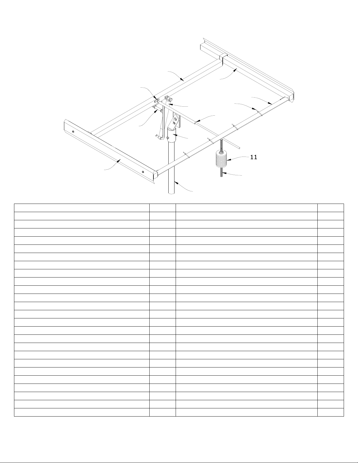
Module Mounting Hardware ( x # of modules ) Quantity
Counterweight Bar & Counterweights ( #11 & 12 ) Quantity
2" Stainless Steel J-Clip 4 ea. 5/8" ZP All Thread Bolt ( 17 1/4" long ) 1 ea.
1/4"-20 x 5/8" SS Hex Bolt 4 ea. Rubber Hose ( 5 1/2" long ) 1 ea.
1/4"-20 x SS Hex Flange Lock Nut 4 ea. 5/8" ZP Hex Nut 2 ea.
1/4" SS Flat Washer 4 ea. 5/8" ZP Flat Washer 2 ea.
5/8" ZP Lock Washer 2 ea.
5/8" ZP Jamb Nut 1 ea.
2 1/2lb Disk Weight 8 ea.
RECOMMENDED TOOLS:
•(2) 15/16” combination wrenches •(2) ¾” socket or combination wrenches
•(2) 9/16” combination wrenches •(1) flathead screwdriver
•(2) ½” combination wrenches •(1) 7/16” socket or combination wrench
NOTE TO INSTALLER: The installer MUST provide the schedule 40 steel pipe. Before assembling your
Track Rack™, use the list above to assure that you have all of your components. In the event that you may have
missing parts, contact Zomeworks Customer Service @1-800-279-6342.PLEASE have your SALES ORDER
NUMBER,SERIAL NUMBER,DATE OF PURCHASE, along with your DEALER NAME when calling.
UTR-SERIES POLE INSTALLATION
IMPORTANT NOTE: ZOMEWORKS CORP. ASSUMES NO LIABILITY FOR THE STRUCTURAL
INTEGRITY OF THE POLE AND ITS INSTALLATION. SOIL AND WIND CONDITIONS VARY. IF THERE
IS ANY DOUBT, CONSULT WITH A LOCAL STRUCTURAL ENGINEER.
LOCATION CONSIDERATIONS:
For installations in sandy or muddy areas, for tall mounting poles, or for any mounting different from the
situations described in these instructions, you will need to consult a local structural engineer. Large TRACK
RACKScan receive significant wind loads, so a strong mounting pole and foundation is very important. Also,
be aware of turbulence near buildings or sudden changes in terrain. The site should receive the maximum
possible sunlight from AM to PM, in the winter and summer. Avoid shade from buildings and trees, including
shade that may occur in other seasons. The height of the pole should result in adequate ground clearance for the
mounted modules.
CAUTION – BE CAREFUL WORKING AROUND THE RACK AFTER INSTALLATION ON THE
POLE. SOME OF THE STRUCTURAL MEMBERS MAY BE AT HEAD LEVEL.
•The customer provided pole is a 2 1/2” (nominal) schedule 40 steel pipe with a 3” OD. Pole can be black or
galvanized steel pipe.
•Note: Heavier schedule steel pipe schedule 80, schedule 160 can be used as long as OD is 3”.
•Using the chart below, find the MINIMUM acceptable pole height above your finished grade. It is strongly
recommended that the pole height be to our minimum specifications.
•The minimum recommended hole depth is 1/3 the pole length, 1/3 in the ground, 2/3 above the ground.
Example: 5’ below grade, 10’ above grade, total of a 15’ pole.
•Center the pipe in the hole, and using a level, make sure pole is vertical.
•Fill the hole with concrete (3000-psi minimum strength), and check level of the pole.

6
•The pole may be filled with concrete for added strength (only to approximate ground level).
•Allow concrete and pole to set for a minimum of 36 hours BEFORE installing the Track Rack™.
MOUNTING POLE RECOMMENDATIONS:
40" 29"
6"
(6-5
8" OD)
6"
(6-5
8" OD)
SCHEDULE 40
STEEL PIPE
SLOPE AWAY FROM
POLE FOR DRAI AGE
F-Series
UTRF168
CO CRETE
EARTH
72"
144"
8"
(8-5
8" OD)
30" diameter
Pipe set in
concrete
169" EW
120" NS
168 Sq. Ft. of
Module Area POLE INSTALLATION DETAIL
18" to 30"
50"
F-Series
UTRF90
60"
120"
54"
108"
Description
Min. Pole Height
Min. Pole Depth
Minimum
Schedule 40
Steel Pipe
F-Series
UTRF64
6"
(6-5
8" OD)
96"
48"
24" diameter
Pipe set in
concrete
146" EW
120" NS
90 Sq. Ft. of
Module Area
Minimum
Recomended
hole diameter
Rack
Dimensions
(up to but NOT to
exceed Sq. Ft.)
124" EW
80" NS
64 Sq. Ft. of
Module Area
24" diameter
Pipe set in
concrete
Ground Clearance at
45° Tilt N/S & E/W
33"21"30"
F-Series
UTRF120
146" EW
120" NS
120 Sq. Ft. of
Module Area
24" diameter
Pipe set in
concrete
Universal
UTR-020
76"
2.5"
(2-7
8" OD)
18" diameter
Pipe set in
concrete
67" EW/
44" NS
20 Sq. Ft. of
Module Area
38"
K-Series
UTRK-040
84"
3"
(3-1
2" OD)
18" diameter
Pipe set in
concrete
124" EW/
48" NS
40 Sq. Ft. of
Module Area
42"
IMPORTANT NOTE: TO MINIMIZE CONFUSION DURING INSTALLATION MOST
OF THE HARDWARE MENTIONED IN THE FOLLOWING STEPS WILL COME
PARTIALLY ASSEMBLED ON THEIR RESPECTIVE PARTS. WHEN RE-
INSTALLING THE HARDWARE PLEASE MAKE SURE TO FOLLOW DIAGRAMS
EXACTLY TO MINIMIZE POSSIBILITY OF DAMAGE TO TRACKER.

7
Step 1: Laying out the canister set:
SOUTH
ORTH
Diagram 1
•Remove Canister set from box and carefully unwind the copper transfer tube and place on the ground or
work surface as shown. Make sure canister tabs are on the bottom.
Step 2: Bottom Rail attachment:
Diagram 2a

8
•Separate the top rail and bottom rail and slide the bottom rail in between the canister tabs and the crossover
tube.
ORTH
SOUTH
Diagram 2b
•Remove the 3/8” Bolts, Washers and Nylock Nuts from the Hardware bag and insert them through the
bottom rail and canister tabs as shown and tighten completely.
•Secure the 4-UV Cable Ties around both the bottom rail and the transfer tube, making sure not to pinch the
transfer tube between the cable tie and the bottom rail. This step can be completed at a later time if so
desired.

9
Step 3: Attaching the Axle Assembly:
ORTH
SOUTH
Diagram 3
•Remove the Axle Assembly from the box. The axle assembly will have the shock and bumper bolt taped to
the bent rod. There is no need to remove them as it will make this step more difficult. The shock is also
already pre-attached to the bent rod and secured with a cotter-pin.
•Remove the shaft-collar and slide over the end of the axle and as far up as possible and lightly secure with
the provided 5/32” Allen Wrench.
•With the axle assembly in the position shown slide the axle through the bearing on the bottom rail until the
bearing comes in contact with the shaft collar. It may be necessary to wiggle the axle as you slide it through
the bearing.
•The Gimbal can also come pre-attached; it is not necessary to remove it.

10
Step 4: Top Rail Attachment:
ORTH
SOUTH
Diagram 4a
•Remove the remaining rail from the box and position as shown in Diagram 4a & 4b.
•Slide the rail U-brackets over the canisters and slide the entire rail up against the axle assembly, making
sure to seat the axle into the bearing on the top rail.
ORTH
SOUTH
Diagram 4b

11
•Remove the 5/16” bolts, flat washers and Nylock nuts from the hardware bag and insert them through the
top rail U-brackets as shown in Diagram 4b and tighten enough to keep the rails from sliding on the
canisters.
Step 5: Mounting the Tracker on the pole:
ORTH
SOUTH
Diagram 5
•On the gimbal can that is mounted to the axle assembly, make sure to loosen the set bolt to allow enough
space for the mounting pole to slide inside.
•While holding the top rail firmly in place against the north end of the axle assembly, lift the tracker atop the
pole.
•When you lift the tracker off of the ground allow the axle assembly to rotate downward as shown in
Diagram 5.
•Lower the gimbal can onto the pole and tighten the set bolt. This may distort the gimbal can a slight bit, but
that is normal. Make sure not to cross thread the set bolt as this will allow the tracker to spin atop the pole.
For added protection against spinning, the installer could pre drill a ½” hole in the mounting pole for the set
bolt to slide into.

12
Step 6: Shock and Bumper Bolt installation:
ORTH
SOUTH
Diagram 6
•Remove the tape and shrink wrap from the shock absorber and bumper bolt.
•Align the upper mount of the shock absorber with the square nut that is welded onto the top rail.
•Apply Loctite to the shock bolt then thread bolt into nut as far as it will go and tighten the jamb nut against
the welded nut.
•Thread the bumper bolt into the square nut that is welded to the north side of the axle assembly on the bent
rod. Repeat the bolt tightening process of the shock absorber with the bumper bolt.

13
Step 7: Shadow Plate Installation:
ORTH
SOUTH
(4) 1/4"-20 x 3/8" ZP ROU D HEAD SLOT SCREWS
(4) 1/4" SS LOCK WASHERS
(4) 1/4" ZP FE DER WASHERS
SHADOW PLATES
Diagram 7
•Remove the shadow plate hardware bag from within the main hardware bag. There will be one extra set of
hardware.
•Screw the ¼” round head slot screws through the lock washer and then the fender washer, through the
shadow plate and into the welded rectangular nuts on the canisters.
•Make sure that the Zomeworks logo is right side up on one of the shadow plates.
•The tracker will NOT function WITHOUT the shadow plates installed.

14
Step 8: J-clip attachment:
ORTH
SOUTH
2" SS J-CLIPS
Diagram 8
•Remove the J-clips from the hardware bag and slide onto the top and bottom rails from the bottom as shown
in Diagram 8. The J-clips on the bottom rail should be mounted with the tab facing the top rail.

15
Step 9: Panel installation:
Diagram 9
•Remove the ¼” Stainless steel module mounting hardware bag from the main hardware bag and fasten one
side of the center solar panel, or if there are two panels then choose which to fasten first, to the top rail as
shown in Diagram 9. When choosing the solar panel mounting holes, choose the holes that are 32” or less,
center to center. There should also be at least 2” between the edge of the solar panels and the canisters
to prevent inadvertent shading.
•Loosen the 5/16”x 3” bolts on the top rail U-brackets and slide the canisters and bottom rail away from the
top rail until the J-clips on the bottom rail align with the second set of mounting holes on the solar panel.
This should be done by grasping each canister by the south end and pulling south.
•Re-tighten the 5/16” x 3” bolts on the top rail U-brackets and finish fastening the solar panel to the bottom
rail. You may also fasten the remaining panels to both of the mounting rails.
•You can now fully tighten all of the U-bracket bolts.
•After all bolts have been tightened and all solar panels installed, loosen the shaft collar and slide down the
axle so that it just rests on the bottom rail bearing and tighten.
•One word of warning, the solar panels MUST be equally spaced from the center-line of the tracker in order
to track the sun correctly.

16
Step 10: Counterweight Installation:
Diagram 10a
•Remove the Counterweight bar and the box containing the 8 – 2 1/2lb weights from the shipping box.
•Remove the nuts and washers from the side of the counter weight bar opposite of the jamb nut and slide all
of the 2 1/2lb weights onto the bar and over the rubber sleeve.
•Re-thread the nuts and washers that were removed in the previous step, back onto the counterweight bar.
•Thread the counterweight bar into the welded nut on the lower side of the bottom rail according to Diagram
10b and tighten the jamb nut against the welded nut. We will worry about balancing the tracker later.
1/8"
MI .
COU TERWEIGHT
BAR
JAMB UT
HEX UT
LOCK WASHER
Diagram 10b

17
Step 11: Balancing the Tracker:
•The Tracker MUST be balanced above its pivot axis.
•Adjust the tracker to the seasonal adjustment required for your area and season.
•Carefully watch the tracker during its normal operation. At the end of its rotation the tracker should just
come to rest on the bumper bolt.
•With the counterweights at their lowest location on the counterweight bar, the tracker may not rotate in its
full arc throughout the day.
•If the tracker stops short of the bumper bolt, move the counterweights up the counterweight bar an inch or
two until the tracker just rests on the bumper bolt.
•If the weights are moved too far up the counterweight bar, the tracker may become top heavy and will not
track correctly. A top-heavy tracker will constantly hunt for and overshoot the sun.
Step 12: Seasonal Adjustment:
•In such installations where the tracker is in a remote location then the tracker should be set at your latitude
year round. To do this, adjust tracker to face the sun at mid-day on or around the 20th of March.
•If the tracker is installed in a location that would allow multiple seasonal adjustments then follow the steps
below.
°In March position the tracker 15 degrees above your latitude and leave at this setting until September.
°In September reposition the tracker to 15 degrees below your latitude and leave at this setting until
March.
•See Diagram 12 for seasonal adjustment positions.
5° 20° 30° 45°
Diagram 12
•GO BACK AND MAKE SURE ALL BOLTS AND SCREWS ARE TIGHTENED.
•ZOMEWORKS ALSO RECOMMENDS GREASING THE ENTIRE BARE-METAL PORTION OF
THE AXLE WITH A HEAVY DUTY GREASE TO PREVENT THE ONSET OF CORROSION.

18
UTR-SERIES TRACKER TROUBLESHOOTING
TRACKER SITS LEVEL, LEANS TO ONE SIDE, OR DOES NOT MOVE:
1. Manually move tracker through its entire range of motion. Check for any mechanical interference and
correct if necessary. You MUST grease the bearings regularly, AT LEAST TWICE A YEAR (See
warranty).
2. Check shadow plates for proper installation. The tracker will NOT work WITHOUT them.
3. Be sure the Track Rack™ is pointing south (in the Northern Hemisphere), the copper transfer tube is
mounted on the south end of the frame and the tube is not crimped in any way.
4. Check for any wiring which may stop the Track Rack™ from turning freely. Check wiring and junction
boxes for equal balancing on the east and west sides.
5. A shock absorber may be sticking. On a calm sunny day remove the shock from the top rail. If it tracks
without the shock, call ZOMEWORKS. The shock absorber may be defective. (SHOCKS ARE
WARRANTED FOR 2YEARS ONLY)
6. The Track Rack™ moves when sunlight warms one canister, which then forces refrigerant into the cooler
canister. You may simulate the sunlight’s effect by warming the lower canister with a hair dryer or
carefully with a hand torch (Alternately, you may also cool the upper canister with wet towels or a cold
water spray). Within 10 minutes, the Tracker should begin to rotate towards the cooler canister. If the
Track Rack™ does not move, and you have checked the assembly for movement, the Tracker may have lost
its charge. Call your dealer or your ZOMEWORKS representative.
TRACKER IS SLOW TO WAKE UP:
1. Check that Track Rack™ is getting full early morning sun shining underneath the tracker. The canisters
must “see” the sun.
2. Check modules and electrical junction boxes for equal balancing on the east and west sides.
3. Check bearings for lubrication so the tracker moves freely.
NOTE: IF THE TRACK RACK™ IS INSTALLED IN A CORROSIVE CLIMATE, CHECK THE
AXLE AND BEARINGS FREQUENTLY FOR RUST OR CORROSION; YOU WILL NEED TO
GREASE YOURS 2 - 3 TIMES PER YEAR. COATING THE AXLE AND BEARINGS WITH
GREASE WILL HELP PREVENT CORROSION.
4. The shock absorber may be sticking when collapsed or extended. Remove the shock bolt at the top rail and
check the shock motion for “stick”. If the tracker “wakes up” without the shocks, the shocks are likely
defective. Contact your dealer or ZOMEWORKS for replacement. DO NOT LEAVE THE TRACKER
DEFENSELESS WITHOUT SHOCKS; A STRONG WIND COULD DAMAGE IT. TIE IT DOWN.
TRACKER DOES NOT HIT THE BUMPER STOPS:
1. The tracker is very effective even if it doesn’t track to the bumper limits. The bumper stops are set for
approximately 90°of rotation.
2. To increase the rotation, raise the counterweight. But remember: raising the counterweight will make the
tracker less stable in the wind. For optimum performance you must balance rotation against stability. If the
tracker rotates further to one side than the other, the tracker may be out of balance, refer to Step 11 of the
instructions and rebalance the rack.

19
IMPORTANT NOTES TO REMEMBER:
1. The Track Rack™ must be assembled according to the instructions.
2. The Track Rack™ should move smoothly through the entire range of motion, with the only drag supplied by
the shock absorbers. If friction or interference is noted, check assembly against the instructions and make
required corrections.
3. The photovoltaic modules should be centered and mounted evenly as per the instructions. The canisters on
each side of a Track Rack™ should not be “shaded” by the photovoltaic modules.
YOU MUST MAINTAIN AT LEAST A 2” MINIMUM CLEARANCE, see Step 9.
4. Counterweight must be properly adjusted per instructions.
5. The Track Rack™ must be in a location that maintains a clear line-of-sight to the sun throughout the day,
and during different seasons. Remember that the sun’s position in the sky changes from season to season.
6. To maintain optimum sun exposure you may want to adjust your Track Rack™ for the winter & summer
seasons. See Step 12.
7. A shadow from structures, trees or other objects that may miss the Tracker in the summer may fall across it
in the winter, preventing its operation.
MAINTENANCE:
1. The maintenance required is lubrication of greaseable bearings TWICE A YEAR and paint touch up if
necessary to prevent rusting.
2. If the Track Rack™ is installed in a corrosive climate, check the axle and bearings frequently for rust or
corrosion; you may need to grease the bearings 3 to 4 times per year and keep the axle coated with grease.
3. Check that the shock bolts and shock arm bracket bolts are tight. A tracker is defenseless against the wind
without functioning shock absorbers. If the tracker, for whatever reason, does not have shocks attached
secure the tracker in one position to prevent wind damage.
IMPORTANT FINAL NOTE:
YOUR ZOMEWORKS TRACK RACK™ WILL MOVE IN THE WIND,
MUCH AS TREES DO. THIS MOTION IS EXPECTED AND DOES NOT
HARM THE TRACKER OR ITS PERFORMANCE. UNLESS THE
TRACKER IS BLOWN FAR OFF THE SUN AND STAYS THERE, THE
ENERGY GAIN IS HARDLY AFFECTED. OVERALL, TRACK RACKS™
FAR EXCEED THE PERFORMANCE OF A FIXED ARRAY. IF HIGH
WINDS ARE EXPECTED, AS IN A HURRICANE, SECURE THE
TRACKER AS HORIZONTAL AS POSSIBLE AND TIE DOWN.

20
ZOMEWORKS TRACK RACKTM
Limited Warranty
Zomeworks Corporation guarantees, to the original owner, its Track Rack™ passive solar tracker and fixed
racks against defects in materials and workmanship for TEN YEARS from date of purchase. Shock absorbers
and Bearings are warranted against defects in materials and workmanship for TWO YEARS from date of
purchase. An extended warranty for shock absorbers and bearings is available; please contact Zomeworks
Corporation for details.
This warranty is limited to the repair or replacement of the Track Rack™ in compliance with the instructions
provided by Zomeworks. IT IS THE OWNER’S RESPONSIBILITY TO GREASE THE BEARINGS AT
LEAST TWICE PER YEAR.
Some problems can be solved with a simple on site adjustment. Please contact Zomeworks Corporation at the
address and phone number below before returning your product. You must have an RMA number to return the
product for warranty repair. If possible, return only the parts that are defective or damaged. Reuse your
original packing material, if it’s available, or call the factory for further instructions.
IT IS THE OWNER’S RESPONSIBILITY TO CHECK FOR DAMAGED OR MISSING PARTS
IMMEDIATELY UPON RECEIPT OF THE TRACK RACK™. Freight claims are time sensitive and
require immediate notice. If the packaging is damaged, write this on the receipt (freight bill) and have the
driver initial this. Use this information to contact your freight carrier when damage is noticed.
Upon receipt of a defective part(s), freight pre-paid, Zomeworks will determine whether the defect was caused
in manufacturing. If so, the part(s) will be repaired or replaced at no charge to the customer, and will be
returned freight pre-paid. If the damage is not a manufacturing defect, the factory will contact the customer
before any repairs are made. Original owners should contact their dealer if an immediate replacement part(s)
are needed. Individuals contacting Zomeworks Corporation desiring immediate replacement part will be
required to provide Zomeworks Corporation with a valid credit card number to be charged for the replacement
part(s). Zomeworks Corporation will credit the valid credit card upon receipt of the warranted returned part(s)
from the individual.
This warranty does not cover rusting of the steel due to a corrosive environment (such as salt air). Standard
Track Racks™ are painted mild steel and will require maintenance. It is the owner’s responsibility to maintain
the paint on the Track Rack™ in order to protect the steel against corrosion. For corrosive environments,
Zomeworks Corporation can manufacture the Track Racks™ with an epoxy primer.
Limitations on Warranty
The above ten-year and two-year warranties are the only warranties and remedies provided by Zomeworks to
user. Zomeworks disclaims all implied warranties of merchantability and fitness. In no event shall Zomeworks
be liable for consequential or incidental losses or damages under any theory of liability, except to the extent that
this limitation is found to be unenforceable under applicable state law. Some states do not allow the exclusion
or limitation of incidental or consequential damages, so this exclusion may not apply to you. This warranty
gives you specific legal rights, and you may also have other rights that vary from state to state.
1011 Sawmill Rd. NW, PO Box 25805, Albuquerque, NM 87125 USA
(505) 242-5354 / (800) 279-6342 / FAX (505) 243-5187
E-mail [email protected]
Other manuals for UTR-020 TRACK RACK
1
Table of contents
Popular Solar Panel manuals by other brands

SunWare
SunWare RX Series installation manual

SR PORTABLES
SR PORTABLES MC4 instruction manual

Energetica
Energetica E-2000 Series Operating and installation guide

Centrosolar
Centrosolar CENPAC Series Mounting instructions

Segway
Segway SP-100 user manual

Kyocera
Kyocera KD Series Assembly and maintenance instructions

First Solar
First Solar CuRe 6 Series user guide

SOVA SOLAR
SOVA SOLAR SS35572MC Installation & service instructions manual

LYSON
LYSON W3118 instruction manual

SunEdison
SunEdison Silvantis P300 installation manual

Recom
Recom RCM 6MB Series Installation and safety instructions

Anker
Anker SOLIX PS400 user manual