RECEIVER SETUP
Section 6, Page 9 May 2002
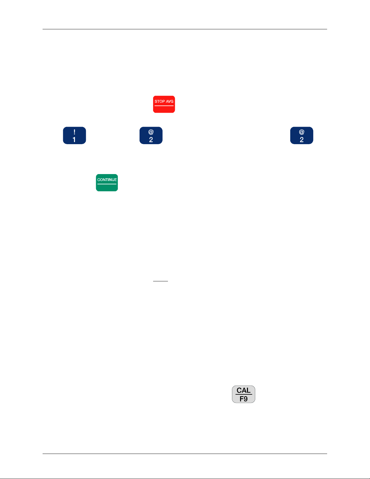
STOPPING A CALIBRATION WHILE IN PROGRESS
NOTE: To avoid confusion, Zonge strongly recommends that the entire calibration be
performed in one continuous sequence, rather than in segments. If a problem arises that
requires the calibration to be prematurely aborted, it is recommended that the entire sequence
be repeated after resolving the issue.
At times it may be necessary to stop the calibration process (i.e. to change the number of cycles).
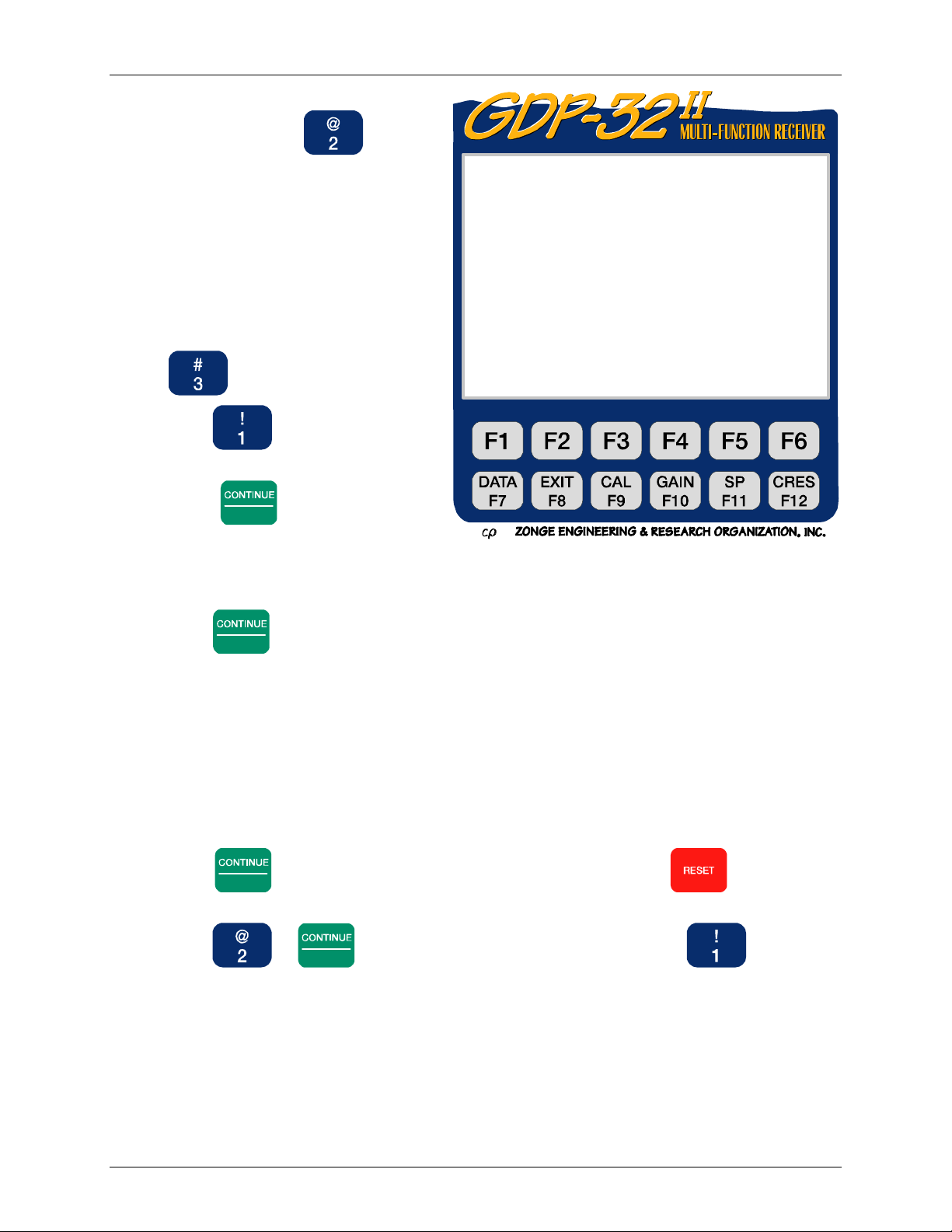
To stop the calibration process, press Escape . The Instruction Line now displays:
Exit autocal mode? (1 - yes,2-no)
Press to exit. Press to change parameters. Upon pressing the
Instruction Line displays:
Press CONTINUE when values are correct
The cursor appears in the “cycles” field of the Data Acquisition Screen. After changing
parameters, press Enter to resume the calibration.
To view calibrates, see section 7.3 for instructions about how to access board calibrate caches.
Calibrations are written to the Field Data cache as well as the Calibration cache so that there is a
permanent record of the calibration values. Access the Calibration cache of interest and you will
notice that the date, time and condition of the power line notch filter at the time of the calibration
are all recorded in the Calibration header.
SYSTEM CHECK
NOTE: A summary of the System Check procedure is located in the Quick Start Section.
Perform a system check to check the quality of a calibration. This process is similar to a system
calibration except that the results are NOT stored in a Calibration buffer, only in the Field Data
buffer. Calibration corrections are applied to the results, which are then displayed to the screen.
Hence, the system check is a good way to look at the quality of a calibration. The ideal result in
phase should be zero milliradians.
Following is a typical reason for using the system check utility:
Assume that three-frequency RPIP data are being acquired, and late in the day you discover that
the phase data all decrease suspiciously at the high frequency. A bad calibration or a receiver
problem is possible and can be quickly confirmed or rejected by doing a system check at the
suspect frequencies. If the phase differences in the decalibrated system check display are zero or
nearly zero, the present calibration is the same as the earlier one. So long as the calibration
procedure is correct and the calibration agrees with earlier calibrations, the explanation for the
problem must be found elsewhere (i.e. faulty analog card, field wire problem, etc.).
1. Set the frequency value to check (e.g. 0.125 Hz)
2. From a survey program’s Data Acquisition screen, press . Select the Calibrate or
the System Check Mode.