Zoomlion FE10 User manual

Instruction for use of the forklift with the triple pivot battery
Contents
I. Safety rules for driving and operation of battery forklift................................................................................. 1
1.1 Overview ..................................................................................................................................................... 1
1.2 Forklift transportation.................................................................................................................................. 1
1.3 Precautions on Parking................................................................................................................................ 1
1.4 Preparations before use................................................................................................................................ 1
1.5 Precautions on operation.............................................................................................................................. 2
1.6 Charge of battery pack................................................................................................................................. 3
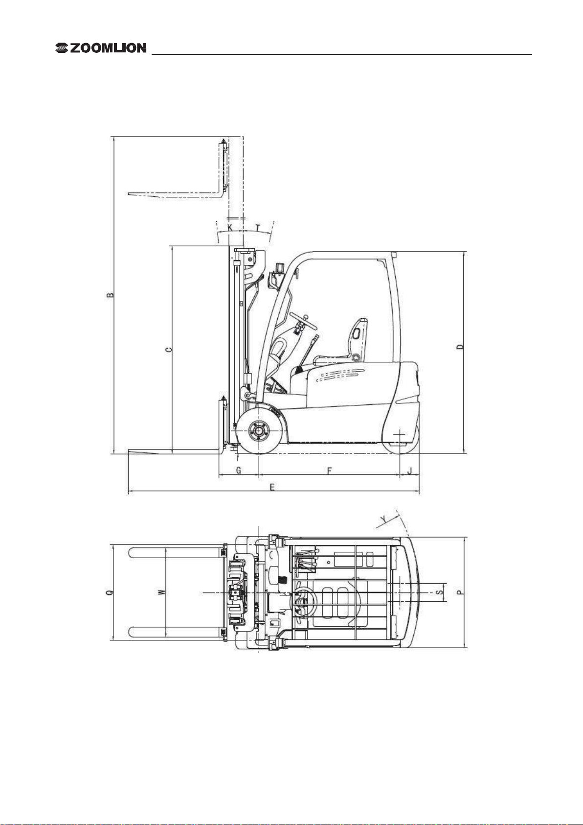
II. Dimension drawing of battery forklift.............................................................................................................. 4
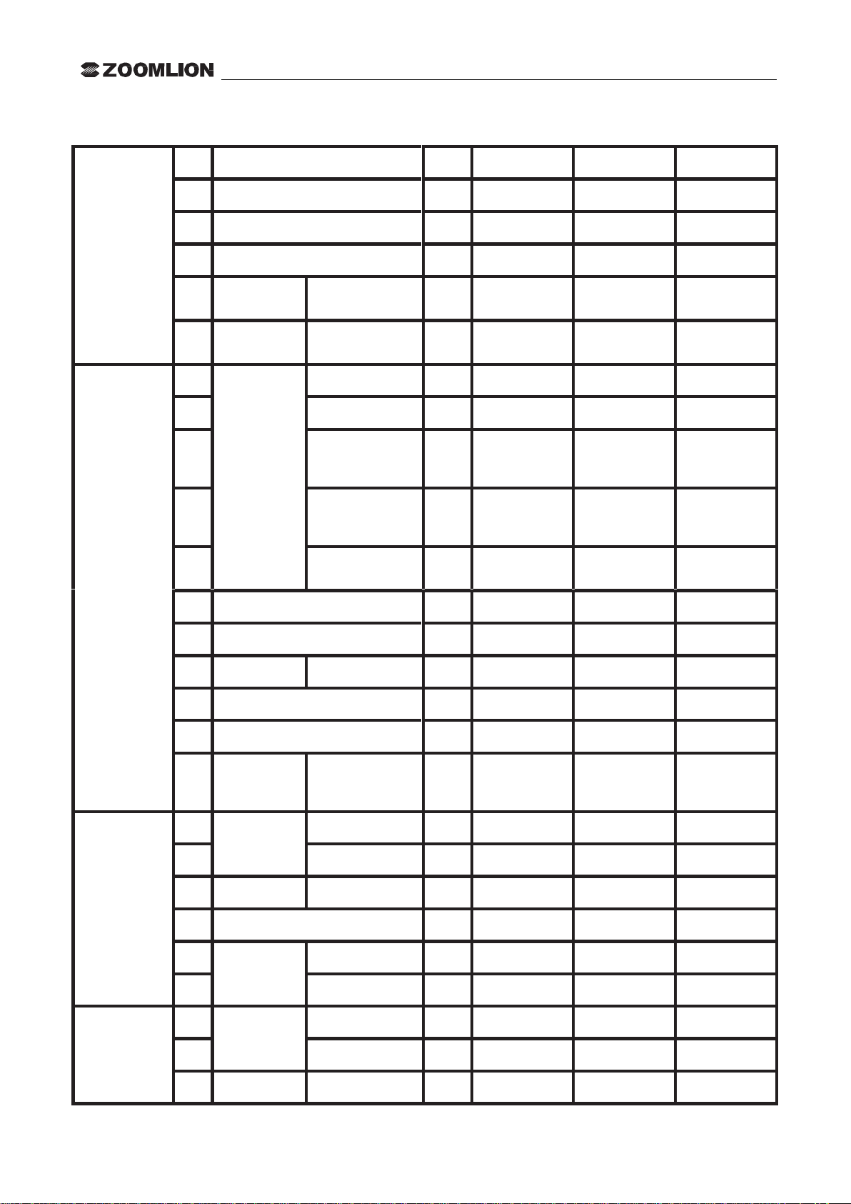
III. Main technical parameters of 1-12T triple-pivot battery forklift................................................................. 5
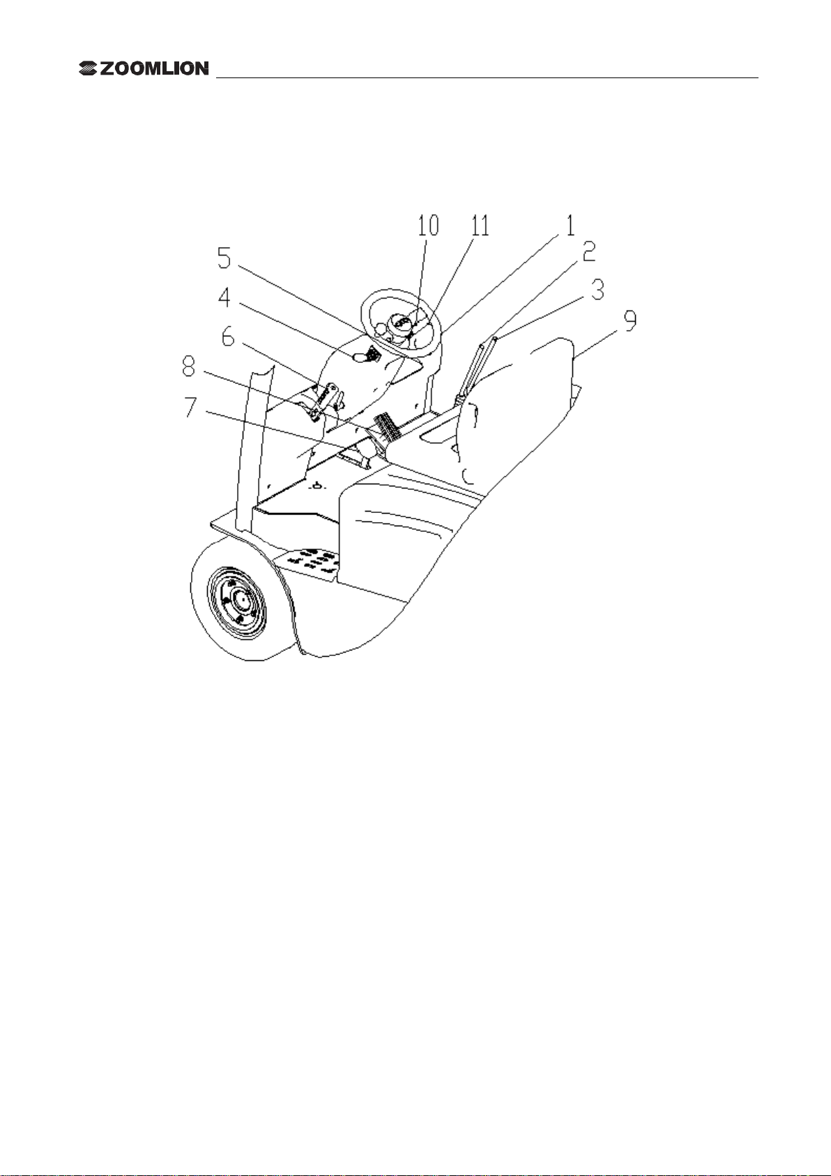
IV. Structure and working principle of forklift.................................................................................................... 8
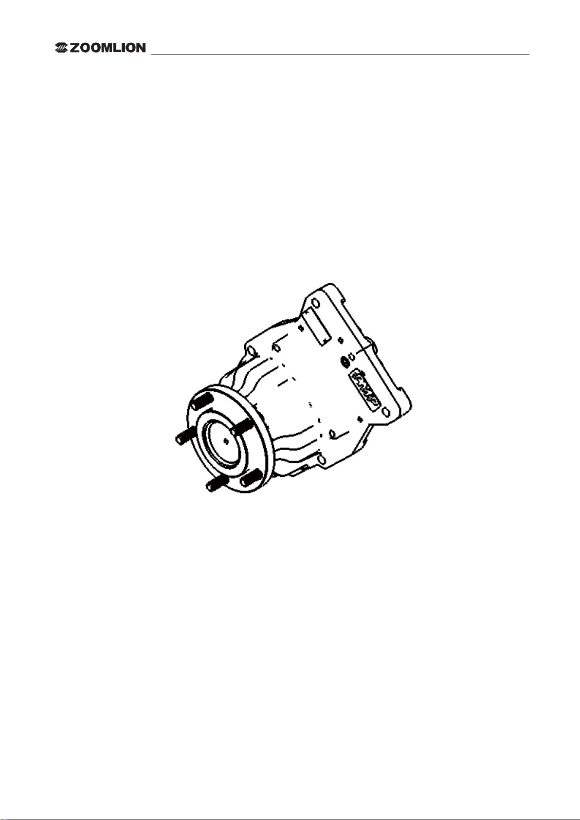
4.1 Drive system (Fig.4-1)................................................................................................................................. 8
4.1.1 Drive axle.......................................................................................................................................... 8
4.2 Steering system............................................................................................................................................ 9
4.2.1 Full hydraulic steering gear ............................................................................................................ 10
4.2.2 Steering cylinder (Fig.4-4).............................................................................................................. 11
4.2.3 Steering axle (Fig.4-5).................................................................................................................... 11
4.3 Brake system (Fig.4-6) .............................................................................................................................. 13
4.3.1 Service brake .................................................................................................................................. 14
4.3.2 Brake master cylinder..................................................................................................................... 14
4.3.3 Adjustment of brake pedal.............................................................................................................. 15
4.3.4 Parking brake.................................................................................................................................. 16
4.4 Hydraulic system (Fig.4-11)...................................................................................................................... 18
4.4.1 Lifting oil pump and steering oil pump (Fig.4-12)......................................................................... 19
4.4.2 Multi-way valve (Fig.4-13)............................................................................................................. 20
4.4.3 Lifting cylinder (Fig.4-14).............................................................................................................. 21
4.4.4 Governor valve ............................................................................................................................... 22
4.4.5 Tilt cylinder (Fig.4-17)................................................................................................................... 23
4.4.6 Hydraulic system fault diagnosis.................................................................................................... 24
4.5 Lifting system............................................................................................................................................ 25
4.5.1 Inner/outer mast (Fig.4-18)............................................................................................................. 25
4.5.2 Pallet fork bracket and load backrest (Fig.4-19)............................................................................. 26
4.5.3 Position of roller (Fig.4-20)............................................................................................................ 27
4.5.4 Forklift fittings................................................................................................................................ 28
4.6. Electric System......................................................................................................................................... 29
4.6.1 Overview......................................................................................................................................... 29
4.6.2 Operating method ........................................................................................................................... 31

Instruction for use of the forklift with the triple pivot battery
4.6.3 Battery............................................................................................................................................. 31
4.6.3.1 Construction of battery ........................................................................................................ 31
4.6.3.2 Battery specification ............................................................................................................ 32
4.6.3.3 Use of battery....................................................................................................................... 32
4.6.4 ENGAGE IV instruments............................................................................................................... 34
4.6.4.1 Overview.............................................................................................................................. 34
4.6.4.2 Display................................................................................................................................. 34
4.6.4.3 Function and application:..................................................................................................... 34
4.6.4.4 Instructions for use............................................................................................................... 35
4.6.4.5 Use and maintenance........................................................................................................... 40
V. Common fault analysis and possessing method of forklift............................................................................ 41
5.1 Drive system.............................................................................................................................................. 41
5.2 Steering system.......................................................................................................................................... 41
5.3 Brake system.............................................................................................................................................. 41
5.4 Hydraulic system....................................................................................................................................... 42
5.5. Electric System......................................................................................................................................... 42
VI. Maintenance of FE triple pivot battery forklift............................................................................................ 43

Instruction for use of the forklift with the triple pivot battery
1
I. Safety rules for driving and operation of battery forklift
1.1 Overview
The concept of "Safety First" has to be borne in mind by the driver and unit manager. The safety operation in
accordance with the Forklift Use and Maintenance Manual and Driver' Safety Operation Manual has to be
observed.
1.2 Forklift transportation
1.2.1 The forklift must be tied as specified during transport:
1.2.2 Draw the parking brake and underlay the counterweight with the lumps of wood:
1.2.3 The lifting is done according to the position as indicated by the "Lifting Sign".
1.3 Precautions on Parking
1.3.1 Lay the pallet fork on ground:
1.3.2 Turn off the electric lock, place all joysticks on N-position and unplug the power plug:
1.3.3Tighten the hand brake;
1.3.4 For the forklift out of service for long-term, the wheels should be built on stilts and the battery should be
charged once a month.
1.4 Preparations before use
1.4.1 Read the instructions and accompanying documents and be familiar with the positions of instruments and
every control mechanism (Fig.1-1), driver has to know about the structure and properties of forklift and certify
for the post with the driving license;
1.4.2 Check whether the instruments work properly;
1.4.3 Check whether the battery voltage is within the normal range and whether the electrolyte solution gravity
and liquid level are appropriate;
1.4.4 Check whether all connectors and plugs of electric system are in reliable contact and whether the pedal
adjustment are flexible;
1.4.5 Check whether the foot brake and hand brake are reliable;
1.4.6 Check whether the hydraulic oil and brake fluid are normal;
1.4.7 Check whether the lighting and signal light are normal.

Instruction for use of the forklift with the triple pivot battery
2
1.5 Precautions on operation
1.5.1 Pay attention to the performances and working conditions of mechanic, hydraulic, electric and AC motor
governor controller;
1. Steering wheel
4. Direction switch
7. Brake pedal
10. Turn signal light switch
2. Lift lever
5. Instrument panel
8. Acceleration pedal
11.Lightswitch
3. Tilting lever
6. Hand brake lever
9. Seat
Fig.1-1
1.5.2 To connect voltage, turn on the key switch at first, be sure of the position of direction switch, rotate the
steering wheel and check whether the forklift runs properly, slowly step the governor control pedal while
holding appropriate starting acceleration:
1.5.3 Observe the instrument panel. If the display of battery capacity is lower than 10%, you should stop the
operation immediately and charge or replace the battery:
1.5.4 Slow down in advance when making the turns:
1.5.5 When driving and stacking cargo, it is inappropriate to carry out the joint operation. The lifting weight and
running speed should be reduced when working on poorer site pavement:
1.5.6 Overload is not allowed. If the cargo is in larger dimension, the ratings as indicated in the load curve sign
should be observed when the gravity moves forward:

Instruction for use of the forklift with the triple pivot battery
3
1.5.7 The pallet fork should be kept in appropriate distance to avoid the eccentric load:
1.5.8 When the cargo approaches the fork wall, it should be lowered in height as much as possible, the mast
leaned back to allow the driving of forklift:
1.5.9 To ensure safety, no persons are allowed to stand beneath and on the pallet fork for lifting:
1.5.10 When the cargo is lifted or lowered, the initial velocity should be not too fast:
1.5.11 When the mast tilts forward or backward to the limiting position or the pallet fork lifted to the maximum
height, the operating handle should be quickly returned to the middle position:
1.5.12 When the cargo is conveyed by a forklift, use of emergency braking should be avoided as much as
possible to prevent the cargo from being thrown out or personnel injury.
1.6 Charge of battery pack
1.6.1 When the battery pack is charged initially and added afterward, the provisions in the battery instructions
should be strictly observed:
1.6.2 When the forklift is in operation, the battery capacity on the instrument panel is less than 10% or the
voltage of any single battery lower than 1.70V, you must stop working with the forklift until the battery pack
has been charged or replaced:
1.6.3 When in charge, check always the gravity, liquid level and temperature of electrolyte solution.
1.7 The maximum allowable noise value of battery forklift shall not be greater than 80dB (A) and the test
method adopted as per JB/T3300.

Instruction for use of the forklift with the triple pivot battery
4
II. Dimension drawing of battery forklift
Fig.2 1 Profile of the FE forklift with the triple-pivot battery counterweight

Instruction for use of the forklift with the triple pivot battery
5
III. Main technical parameters of 1-12T triple-pivot battery forklift
3.11 Main technical parameters of 1.3T battery forklift
Specifications
1
Model
FE10
FE13
2
Rated lifting weight
kg
1000
1300
3
Load center
mm
500
500
4
Great lifting height
mm
3300
3300
5
Specification of
pallet fork
Length X Width X Thickness
mm
920×100×35
920×100×35
6
Inclination of mast
Front/rear (α°/β°)
Deg
6/6.5
6/6.5
Dimensions
7
Overall
dimensions
All in shortage (No pallet fork)
mm
1854
1854
8
Full width
mm
1100
1100
9
The height where the mast cannot
be lifted
mm
2165
2165
10
Height of mast lifting (with the
load-backrest)
mm
4300
4300
11
Height of overhead guard
mm
1990
1990
12
Minimum turn radius
mm
1480
1480
13
Front overhang
mm
375
375
14
Wheel track
Front/rear
mm
940/180
940/180
15
Min. ground clearance
mm
95
95
16
Wheel base
mm
1290
1290
17
The adjusting
range of pallet fork
Max./min.
mm
200/950
200/950
Performance
18
Speed
Run (full load)
km/h
13
13
19
Lifting (full load)
mm/s
300
300
20
Gradeability
Full load
%
15
15
21
Dead weight (including the battery)
kg
2800
2800
22
Tire
Front
18X7-8
18X7-8
23
Rear
15X4.5-8
15X4.5-8
Drive
24
Motor
Drive motor
kw
4.5*2
4.5*2
25
Pump motor
kw
10
10
26
Battery
standard
V/Ah
48/400
48/400
27
Controller
Manufacturer
CURTIS
CURTIS
28
Working pressure
Mpa
14.5
14.5

Instruction for use of the forklift with the triple pivot battery
6
3.21. Main technical parameters of 6-2T triple pivot battery forklift
Specifications
1
Model
FE16
FE18
FE20
2
Rated lifting weight
kg
1600
1800
2000
3
Load center
mm
500
500
500
4
Great lifting height
mm
3300
3300
3300
5
Specification
of pallet fork
Length X Width X
Thickness
mm
920×100×35
920×100×35
920×100×35
6
Inclination of
mast
Front/rear (α°/β°)
Deg
6/6.5
6/6.5
6/6.5
Dimensions
7
Overall
dimensions
Full length
mm
1954
1954
1954
8
Full width
mm
1100
1100
1100
9
The height where
the mast cannot be
lifted
mm
2165
2165
2165
10
Height of mast
lifting (with the
load-backrest)
mm
4300
4300
4300
11
Height of overhead
guard
mm
1990
1990
1990
12
Minimum turn radius
mm
1580
1580
1580
13
Front overhang
mm
375
375
375
14
Wheel track
Front/rear
mm
940/180
940/180
940/180
15
Min. ground clearance
mm
95
95
95
16
Wheel base
mm
1390
1390
1390
17
The adjusting
range of pallet
fork
Max./min.
mm
200/950
200/950
200/950
Performance
18
Speed
Run (full load)
km/h
13
13
13
19
Lifting (full load)
mm/s
320
300
290
20
Gradeability
Full load
%
15
15
15
21
Dead weight (including the battery)
kg
3150
3300
3380
22
Tire
Front
18X7-8
18X7-8
18X7-8
23
Rear
15X4.5-8
15X4.5-8
15X4.5-8
Drive
24
Motor
Drive motor
kw
4.5*2
4.5*2
4.5*2
25
Pump motor
kw
10
10
10
26
Battery
standard
V/Ah
48/500
48/500
48/500

Instruction for use of the forklift with the triple pivot battery
7
27
Controller
Manufacturer
CURTIS
CURTIS
CURTIS
28
Working pressure
Mpa
17.5
17.5
17.5

Instruction for use of the forklift with the triple pivot battery
8
IV. Structure and working principle of forklift
4.1 Drive system (Fig.4-1)
The travel of forklift with double motors on the triple-pivoted front wheels is powered by the battery. Two
motors respectively drive two set of transmission devices which are driven by the secondary planetary gear. The
motor drives the wheels through the transmission device and moves the vehicle ahead The moving direction of
vehicle is where the vehicle is changed to drive toward by the change in the rotation direction of drive motor, so
that the vehicle achieves the forward or backward motion. Two wheels drive the forklift when making the turns,
two motors respectively controlled by two controllers, rotate the wheels at different speed as required by
cornering to achieve the purpose of turning around.
Fig.4-1 Gearbox/drive axle
4.1.1 Drive axle
The axle housing is the mono-block cast structure. The drive axle and the gearbox are designed in integrated
structure and available with one brake system. The power is driven by the secondary planetary gear and the
front wheel finally driven by the wheel hub. The tires are fitted on the wheel hub through the wheel hub with
the stud and nut.

Instruction for use of the forklift with the triple pivot battery
9
4.2 Steering system
The steering system is composed of the steering oil pump, full hydraulic steering gear, steering cylinder and
steering axle etc.,. The steering shaft is connected to the steering gear through the universal joint and the
coupling shaft to steering wheel through the universal joint. The steering column can tilt backward to the
suitable position. The steering axle is mounted on the tail bracket behind the frame and moved around and
rotated by the helical gear and rack on the steering wheel engaged with the gears on the piston rod inside the
steering cylinder to achieve the steering. (Fig. 4-2)
Fig.4-2 Steering system

Instruction for use of the forklift with the triple pivot battery
10
4.2.1 Full hydraulic steering gear
The full hydraulic steering gear is referred to as the cycloidal full hydraulic steering gear, which is composed of
a common steering gear and a combination valve. The hole on the cap of the combination valve serves as the
system safety valve. In addition, there is a two-way overload valve inside the valve body. It will produce the
high within the hydraulic system when the forklift wheels are subject to accidental shocks during the running.
When being under pressure, it plays the role of protection to prevent the damage on parts. The safety valve and
two-way overload valve were adjusted in plant. Users do absolutely not make adjustment. (Fig. 4-3)
1. Limited post
4. Universal driving shaft
7. Rotor
2. Valve body
5. Leaf spring
8. Stator
3. Valve element
6. Link block
9. Valve sleeve
Fig.4-3 Steering system

Instruction for use of the forklift with the triple pivot battery
11
4.2.2 Steering cylinder (Fig.4-4)
The steering cylinder is the double-acting piston type. There are oil inlets respectively located at both ends of
the piston rod. The pressure oil from the full hydraulic steering gear makes the piston rod move around through
the oil cylinder and thereby to achieve the turning to the left and right.
1. Piston rod
2. Cylinder head
3. Cylinder block
4. "O" ring
5. Support ring
6. Bushing
7. "O" ring
8. Bushing
9. Yx seal ring
10. Gasket
11. Dust ring
12. Sleeve
13. Baffle
Fig.4-4 Steering cylinder
4.2.3 Steering axle (Fig.4-5)
The steering axle is composed of the steering axle, steering axle housing, oil cylinder, rack drive and steering
wheel assembly etc. Move around by the oil cylinder piston rod engaged with the gear through the gear rack,
making the steering wheel turn to achieve the cornering. The steering axle is bolted on the tail bracket behind
the frame.
After the maintenance or replacement of hydraulic parts of steering system, you should carefully check whether
the pipeline is correctly connected, the L/R rotation of steering wheel is normal and the air in the system is
exhausted to avoid accident. During the exhaust, the motor should be activated slightly. When turning the
steering wheel by hand (turn off the power supply at once if there is abnormal phenomenon and find out the
causes for troubleshooting), it should feel easy and flexible, and the steering wheels should deflect accordingly.
Keep rotating around so forth to exhaust the air from the system.
The steering of forklift is activated by the accelerator switch control. Only when the accelerator switch is in
Open state, the motor starts working, the steering acts. In case no driving is carried out, the time for one steering
last about 5~8s, and then the motor will stop running. If continue to make the steering, it is necessary to trigger
once the accelerator switch.

Instruction for use of the forklift with the triple pivot battery
12
1 Component of oil cylinder
2 Piston
3 Seal ring UN40F, 40×50×l0
4 Seal ring UN40D, 40×50×7.3
5 Rack
6Steering gearbox
7 Tapered roller
bearing32011(Class D)
8 Dust ring
9 Briquetting
10 Cross recessed pan head
screw M4 × 35
11 Potentiometer
l2 Adjustment of gasket (I)
13 Adjustment of gasket (II)
14Circlip for the hole 90
15Tapered roller bearing32015
(Class D)
16 Two lips-frame typed rubber
oil seal l10-125-9
17 Gear shaft
18 T-screw of tire: M14×45
19 Hub
20 Wheel hub cover
21 Thin hexagon slotted nut
M24×2
22 Cutter pin 5×40
23 Washer 24
24 Tapered roller bearing 30206
(Class D)
25Tapered roller
bearing30208 (Class D)
26 Two-lips frame typed
rubber seal 48-82-11
27 Steering wheel shaft
28 Conical locknut of tire: M14
29 Steering wheel
30 Fine tuning of screw-plug
31 Coupling shaft of
potentiometer
32 Circlip for the shaft 10
33 Hexagon socket cap
screw M6×55
34Spring washer 6
35Potentiometer seat
36 Deep groove ball bearing
6200(with the dust ring)
37 Elastic cylindrical pin
4×18
Fig 4-5 Steering axle

Instruction for use of the forklift with the triple pivot battery
13
Principle of steering axle:
This steering axle uses the hydraulic oil cylinder l as the power, which pushes the gear rack to drive the gear
shaft l7, hence drives the steering wheel shaft 27 to rotate around the center of gear shaft and achieve the
turning of steering wheel. The rotation angle of steering wheel feeds back the message through the cornering
potentiometer to the electronic controller governed by double motors, which enables two motors to control the
rotation of motor at different speed according to various rotation angles and achieve the harmonized steering of
vehicle.
4.3 Brake system (Fig.4-6)
Brake system includes the service brake and parking brake.
1. Control handle
2. Latch
3. Quadrant plate
4. Rotating sleeve
5. Connector
6. Adjusting bolt
7. Steel cable
8. Brake pedal
9. Return spring
10. Brake master cylinder
11. Oil pipe
12. Bracket
Fig.4-6 Brake system

Instruction for use of the forklift with the triple pivot battery
14
4.3.1 Service brake
The service brake is composed of the brake system master cylinder, brake and brake pedal etc., When it is
necessary to brake during the travel of forklift, you can depress the brake pedal, which will drive the brake
master cylinder, and transfer the hydraulic oil to the brake systems in the L/R gearboxes. The brake disc will
brake up the wheel load under the effect of oil pressure. (Fig. 4-7)
Fig.4-7 Service brake
4.3.2 Brake master cylinder
The master cylinder includes a valve seat, a check valve, a return valve and leather cup, piston and auxiliary
leather cup. The end is fixed with the stop washer and locking wire. The external is protected with the rubber
dust cover. The master cylinder piston is controlled by operating the brake pedal through the push rod. When
the brake pedal is depressed, the push rod will push forward the piston and the brake fluid in the pump body
flows back to the oil tank through the return opening until the oil drain hole is banned by the primary cup. After
the primary cup is pushed over the return opening, the brake fluid in the front cavity of master cylinder will be
compressed and open the check valve resulting in flowing toward the slave cylinder through the brake pipeline.
So each position of slave cylinder piston will extend outward making the friction plate of brake shoe get contact
with the brake drum to achieve the effect of speed reduction or brake. Now, the rear cavity of piston is
supplemented by the brake fluid originated from the return opening and oil inlet. After the brake pedal is
released, the piston is pressed by the reset spring, and at the same time, the brake fluid in each brake slave
cylinder is compressed by the return valve of brake shoe, which brings the brake fluid back to the master
cylinder through the check valve (front cavity of piston) and resets the piston. The brake fluid in the master
cylinder flows back to the oil tank through the return opening. Check the valve pressure and adjust it to a
proportion with residual pressure in the brake pipeline and sub-pump of brake, making the leather cup of slave
Pedal
Axle
Sleeve
Oil storage tank
Brake master cylinder

Instruction for use of the forklift with the triple pivot battery
15
cylinder be correctly positioned to prevent the oil leakage, and eliminate the air resistance possibly occurred in
case of emergency brake.
Fig. 4-8 Brake master cylinder
4.3.3 Adjustment of brake pedal
(1) Shorten the push rod;
(2) Adjust the lock bolt like the pedal height as adjusted in Fig.4 9;
(3) Depress the brake pedal, adjust the push rod until the front end of push rod touches the piston of master
cylinder;
(4) Tighten the lock nut of push rod.
Fig. 4-9
To wheel brake
①Connecting rod
②Push rod
③Dust cover
④Elastic check ring
⑤Auxiliary leather
cup
⑥Piston
⑦Primary cup
⑧Spring
⑨Check valve
Self storing oil tank
Pedal height
Brake switch
Locknut
Pedal stopper

Instruction for use of the forklift with the triple pivot battery
16
Adjustment of brake switch
(a) After the height of brake pedal has been well adjusted, loosen the lock nut of brake switch;
(b) Unplug the plug to disconnect the lead;
© Turn the switch so that the clearance A is equal to l mm;
(d) Confirm that the brake light is On when the brake pedal is depressed.
4.3.4 Parking brake
The parking brake is mechanic and internal expanding. It is built-in on the wheel brake. It shares the brake shoe
and drum with the foot brake. When the handle of parking brake is drawn, the brake handle drives the hand tie
rod through the brake dragline (Fig.4-10). This tie rod pushes the push rod of hand brake to the right with the
help of the pin playing the role of pivot and enables the brake shoe and brake drum to tension and keeps the
wheel from running.
During the driving, you have to completely loosen the parking joystick to get the parking brake switch engaged,
otherwise, the forklift won’t be activated.
Adjustment of brake force: when the regulator is turned clockwise, the brake force increases; when turned
counterclockwise, the brake force decreases.
Traction: 20~30kgNote: adjust by turning the screw inside the regulator.
Brake switch
Lock nut

Instruction for use of the forklift with the triple pivot battery
17
Fig.4-10 Service brake
Right-sided dragline
Left-side cable

Instruction for use of the forklift with the triple pivot battery
18
4.4 Hydraulic system (Fig.4-11)
The hydraulic system is composed of the working pump, multi-way valve, lifting cylinder, tilt cylinder and
pipeline etc.
Fig.4-11 Hydraulic system
Lifting cylinder
Tilt cylinder
Shut-off valve
Governor
valve
Steering gear (with the
combination valve)
Oil
pump
Multi-way valve
Oil pump
Oil filter
Steering
cylinder
This manual suits for next models
4
Table of contents