manuals.online logo
Brands
  1. Home
  2. •
  3. Brands
  4. •
  5. ZPE
  6. •
  7. Network Hardware
  8. •
  9. ZPE Nodegrid Link SR User manual

ZPE Nodegrid Link SR User manual

NodegridLink SR (LSR)
provides extensiveaccess to
the devices attached to it.
Precautions must be taken
to avoid compromising your
securitypolicies.
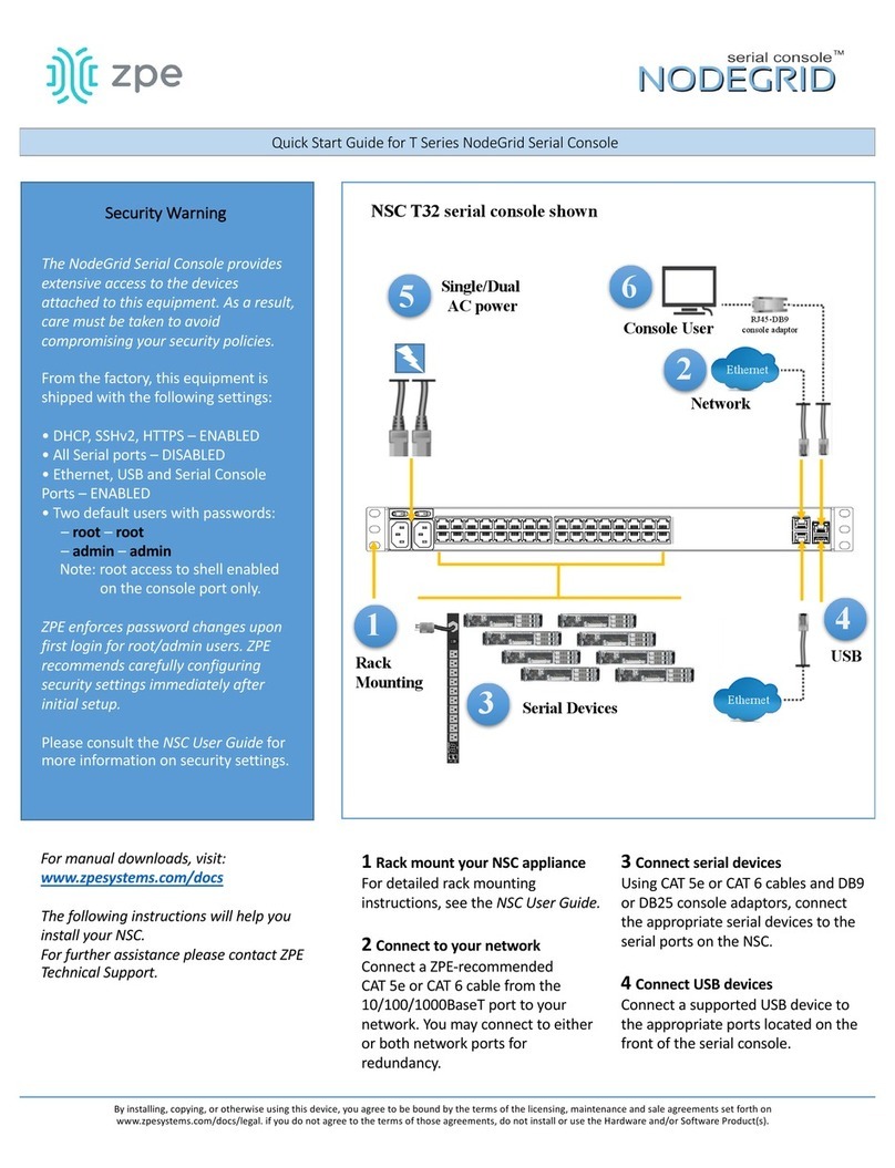
From the factory, this
equipment is shipped with
the following settings:
•DHCP, SSHv2, HTTPS –
ENABLED
•Serial –DISABLED
•All USB, SFP+ , Ethernet ,
and switch ports –
ENABLED
Users will be required to
create a password the first
time they login to the
device.
Note: root access has been
disabled for security
reasons.
Please consult the Nodegrid
User Guide for more
information on security
settings.
Please review the LSR
Safety Information before
installation.
This equipment is intended
only for installation in a
RESTRICTEDACCESS
LOCATION.
Quick Start Guide for Nodegrid Link SR
Security Warning
For manual downloads and support, visit: www.zpesystems.com/document-library/
For further assistanceplease contact ZPE Technical Support. support@zpesystems.com
1Mount your LSR
For detailed mounting instructions, see the Nodegrid
UserGuide whichis available onthe Document
Library.
2Connect to your network
Connect a ZPE-recommended
CAT 5e or CAT 6 cable from the
10/100/1000BaseT port to your network.
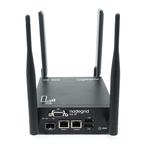
3Connect to the Serial Console port
Using the ZPE’s RJ-45console adaptor, connecta
terminal or workstationwithterminal emulator (setto
115200bps, 8, N,1, with no flow control) to the LSR
serial consoleport.
Alternatively, usethe VGA port.
4Connect power cables
Connect the power cable tothe appliance.
5Turn LSR on
Turnon the power switches.
Nodegrid Link SR™
Console
VGA
By installing, copying, or otherwise usingthis device, you agree to be boundby the terms of the licensing, maintenance andsale agreements set forth
on www.zpesystems.com/docs/legal. If you do not agree to the terms of those agreements, do not install or usethe Hardware and/or Software
Product(s).
Desktop
DIN Rail
Wall Mount
or RackMount
GbE
Front
Back
Note: All remainingmanual setupsteps are requiredthe first timeyou configure your LSR.
4G/LTE
Optional
Antenna
Wi-Fi
Optional
Antenna
Option for LSR DC power
adaptor or
DC source
Power
Switch
Key
Description
V1
-
Return
Ground
V1+
10
–57V
4G/LTE
Optional
Antenna
Wi-Fi
Optional
Antenna
1
2
3
4
5
6Configure network parameters
NOTE: Skip to step 7 if you have a DHCP environment.
DHCP is thedefault IP configuration. Ifno DHCP server
is available, please log in to Nodegrid Link SR via its
console orHDMI port using admincredentials and
configure a static IP address using CLI instructions as
follows:
[admin@nodegrid/]#cd /settings/network_connections/ETH0
[admin@nodegridETH0]#set ipv4_mode=static
[+admin@nodegridETH0]#set ipv4_address=10.0.0.10
[+admin@nodegridETH0]#set ipv4_bitmask=24
[+admin@nodegridETH0]#set ipv4_gateway=10.0.0.1
[+admin@nodegridETH0]#show
name: ETH0
type: Ethernet
ethernet_interface = eth0
description =
connect_automatically =yes
set_as_primary_connection = yes
enable_lldp = no
ipv4_mode = static
ipv4_address = 10.0.0.10
ipv4_bitmask = 24
ipv4_gateway=10.0.0.1
ipv4_dns_server =
ipv4_dns_search =
ipv4_default_route_metric = 90
ipv4_ignore_obtained_default_gateway=no
ipv6_mode = address_auto_configuration
ipv6_dns_server =
ipv6_dns_search =
ipv6_default_route_metric = 90
ipv6_ignore_obtained_default_gateway=no
[+admin@nodegridETH0]#commit
7Configure serial, network & USB devices
Note: Your LSR will respond over the network
at 192.168.160.10 if your DHCP server fails or
is unavailable.
Note: To check your current IP address,
connect to the LSR console port and hit Enter
at the login prompt until you see the IP
address of ETH0 interface.
To configure the LSR for the first time via
Network:
a) Opena web browser (HTTP/S)and enter
its IP address inthe address field. Or start
an SSH session to your LSR’s IP address.
b) Log into your LSR as admin.
c) Set your LSR basic configuration:
- Security
Security, Services page: Selectthe desired
services and Ports, cryptographic protocols
and cipher suite levels. Click Save when
finished.
Authentication page: add your Remote
Authentication servers (AD, LDAP, Tacacs+,
Radius and/or Kerberos).
Authorization page: create users groups,
set profiles and assigndevices
- Network
Network Settings tab: Setyour desired
Network parameters. Click Save for each
submenu.
Network Connections tab: Set your desired
Network Interfaces parameters. Click Save
for eachsubmenu.
-Serialand USBports
Managed Devices tab: Enable and
configureyour desired serial andUSB
ports.
- Change Admin Password
At any time, click admin@domain.comin
the upper rightcorner of your screenand
click “Change Password” to change your
system password.
Congratulations!
Your Nodegrid LinkSR is now configured
and ready toaccept users and connections
to its ports and interfaces.
8Additional Configuration
NOTE: Werecommend thatyouset up a
new Administrator account(in admin group
withfull privileges) and usethenew
account instead of the defaultadmin
account.
Add New Users
ClickSecurity tab, Local Accounts, Add, set
options, Save.
Alerts& logging
Set and send alerts by email, SMS, and/or
SNMP.
Power
Control network attached PDU power strips
and server, network and storage devices.
For advanced configurationoptions, how-
tos and tips please refer to your Nodegrid
Link SR UserGuide.
9Get technical updates
To automatically receivefuturefirmware
updates and technical information, signup
here:
www.zpesystems.com/loop/
Quick Start Guide for Nodegrid Link SR
Contact ZPE Technical Support at support@zpesystems.com
TM
Nodegrid Link SR

Other ZPE Network Hardware manuals

ZPE Nodegrid Gate SR User manual

ZPE

ZPE Nodegrid Gate SR User manual

ZPE NodeGrid T Series User manual

ZPE

ZPE NodeGrid T Series User manual

ZPE NodeGrid Flex User manual

ZPE

ZPE NodeGrid Flex User manual

ZPE Nodegrid Hive SR User manual

ZPE

ZPE Nodegrid Hive SR User manual

ZPE Nodegrid Gate SR User manual

ZPE

ZPE Nodegrid Gate SR User manual

ZPE Nodegrid Link SR User manual

ZPE

ZPE Nodegrid Link SR User manual

Popular Network Hardware manuals by other brands

ICT Protege PRT-RDE2-PCB installation manual

ICT

ICT Protege PRT-RDE2-PCB installation manual

ADTRAN U-BR1TE Installation & maintenance

ADTRAN

ADTRAN U-BR1TE Installation & maintenance

Vivotek ND8301 Quick installation guide

Vivotek

Vivotek ND8301 Quick installation guide

Belden HIRSCHMANN IT MAMMUTHUS MTM8000 Series user manual

Belden

Belden HIRSCHMANN IT MAMMUTHUS MTM8000 Series user manual

National Instruments NI-488.2 user manual

National Instruments

National Instruments NI-488.2 user manual

Aetina Jetson AIB-MX11 Series user manual

Aetina

Aetina Jetson AIB-MX11 Series user manual

Dell EMC VEP4600 Setup guide

Dell EMC

Dell EMC VEP4600 Setup guide

ADTRAN IQ 710 Application guide

ADTRAN

ADTRAN IQ 710 Application guide

Wisenet PRN-3205B2 quick guide

Wisenet

Wisenet PRN-3205B2 quick guide

Ross NK Series user guide

Ross

Ross NK Series user guide

Paradyne ACCULINK 3151 CSU Quick reference guide

Paradyne

Paradyne ACCULINK 3151 CSU Quick reference guide

Extron electronics VERSATOOLS MTP Setup guide

Extron electronics

Extron electronics VERSATOOLS MTP Setup guide

LevelOne FNS-1020 user manual

LevelOne

LevelOne FNS-1020 user manual

Brunata BrunataNet GateLAN Bbus/RS485 installation guide

Brunata

Brunata BrunataNet GateLAN Bbus/RS485 installation guide

Beckhoff EJ6910 operating instructions

Beckhoff

Beckhoff EJ6910 operating instructions

Wenglor EtherCAT ZAC50CN0 Series operating instructions

Wenglor

Wenglor EtherCAT ZAC50CN0 Series operating instructions

3Com SuperStack II 3C16971 user guide

3Com

3Com SuperStack II 3C16971 user guide

Bay Networks CLAM Reference manual

Bay Networks

Bay Networks CLAM Reference manual

manuals.online logo
manuals.online logoBrands
  • About & Mission
  • Contact us
  • Privacy Policy
  • Terms and Conditions

Copyright 2025 Manuals.Online. All Rights Reserved.