Zubler Z1 ECO User manual

Z1 ECO PRO
Z1 CAM PRO
Z1 PRO
EN 02-2020
Single suction systems
www.zubler.de

2
0. User information page 4
0.1 Declaration of conformity
0.2 Intended purpose of use
0.3 Technical requirements
1.
Installation of the appliance
page 6
1.1 Scope of supply and accessories
1.2
Installation of the extraction system
1.3 Connection of dust producers
1.3.1
Appliances without interfaces
1.3.2 Appliances with switching output
1.3.3 Appliances with switching output
with a 24 V interface or a 230 V socket
1.4 Intake system
2.
Functional description
page 16
2.1 Control unit
2.2 Commissioning
2.3 Automatic operation
2.4
Selecting and saving suction levels
2.5 Current suction power
2.6 Setting the suction overrun time
2.7
Fine tuning of the automatic operation
2.8
Switching the extraction system off
Content

3
3. Warranty terms page 22
3.1 Filter bag
3.2Main filter
3.3 Exhaust filter
3.4Motor
3.4.1 Motor replacement
3.4.2 Carbon brush replacement
4.5 Spare parts
3.6 Technical structure
4. Error Codes page 33
5. Technical Data page 36
6. Warranty
page 37
7.
Disposal instructions
page 38
Advanced settings are provided by the Zubler Sucti-
on-Technology APP , which is available for Android
tablets or phones.
Therefore follow the users manual of the Zubler Suc-
tion-Technology APP, which is downloadable from
www.zubler.de.

4
0.
0.1 Declaration of conformity
Introduction
Dear customer,
we are pleased, that you have decided for a Zubler extraction system and
hope it will enhance your work. The continuous development of our tech-
nology is based on the co-operation with experienced
dental technicians. The focus lies on the aim to optimize the extraction
technology in the fields of performance, noise and reliability.
Please read this operating manual carefully in order to ensure a prob-
lem-free operation.
We, Zubler Gerätebau GmbH
Buchbrunnenweg 26
89081 Ulm Jungingen
declare, that the product vacuuming unit
Z1 ECO PRO
Z1 CAM PRO
conforms to the health and safety
requirements set out in the directives
2014/30/EC EMV-Directive
2014/35/EC Low-Voltage Directive
2006/42/EC Machines Directive
2011/65/EU RoHS Directive
Any modification not specifically approved
by us voids the validity of this declaration.
Kurt Zubler
ceo

5
0.2 Intended purpose of use
0.3 Operating Environment
Temperature: +5°C bis +40°C
Max. permissible relative humidity: max. 80% (bei 30°C)
Total connected load : 10A
Compressed air, free of oil and moist min.5,0bar
This extraction system is designed exclusively for dry dusts!
Its use for the extraction of other types of dust or gases must be clarified
with the manufacturer before putting into operation.
Work must be stopped immediately and the system switched off in the
event of the appearance of visible clouds of dust or noticeably insufficient
suction power.
Inform your dealer or our service team.
The Z1 is designed for indoor use.
The volume of air circulated by the system and returned to the room may
not exceed 50% of the room air volume in closed rooms.
Use is restricted to persons who have been trained in its handling and are
authorised to do so. We reserve the right to make changes even without
updating this manual.

6
1. Installation of the appliance
1.1 Scope of supply and accessories
1x Z1 ECO/CAM PRO
extraction system
1x Power cable
1x
cable C13/C14 (ECOonly)
1.8m hose 38 mm
1x elbow adaptor 50/40 mm
compressed air hose (6mm)
dustbag with 20l
Special Accessories Item Number
Adaptor C14 / CEE
012-00702
H14-Filter H-Typ 556-0052
Activated carbon filter C-Typ
556-0051
exhaust adapter RD72 /DN75
896-1103
diffusor-holder (without Filter)
556-0057

7
16
1
3
2
2
30
1.2 Installation of the extraction system
Fig. 1
Fig. 2
1.2.1 Suction line
nProvide a sufficiently stable and
leveled surface. Ensure that the
housing does not touch the furniture
to avoid noise production by
resonances.
nIf necessary the unit can be leveled by
turning the feet up/down (Fig.1).
nPlug in the muffle of the enclosed
suction hose to the intake nozzle (2)
and the other side firmly to your intake
system.
Use the enclosed 90° adaptor if
running sideways.
1 Closure
2 Exhaust connection
3 Filter door
16 Diffusor
30
Exhaust Adaptor
1.2.2 Exhaust
nIf using the unit in non-stop operation,
the exhausting air temperature is
increased.
nTo avoid overheating, the exhausting
air must be able to flow out and
spread free.
nIf this is not possible, the diffusor can
be removed and the exhausting air
can be guided with a DN75 hose or
pipe (Fig.2). Therefore use the optional
exhaust-adaptor RD72/DN75 O.No.
896/1103
nTo connect the diffusor to the DN75
hose or pipe you will need the optional
diffusor-holder O.No. 556/0057 (Fig.3)
nAlternatively it is recommended to
giude the exhaust air to the outside.

8
5
10
Fig. 3
Fig. 4
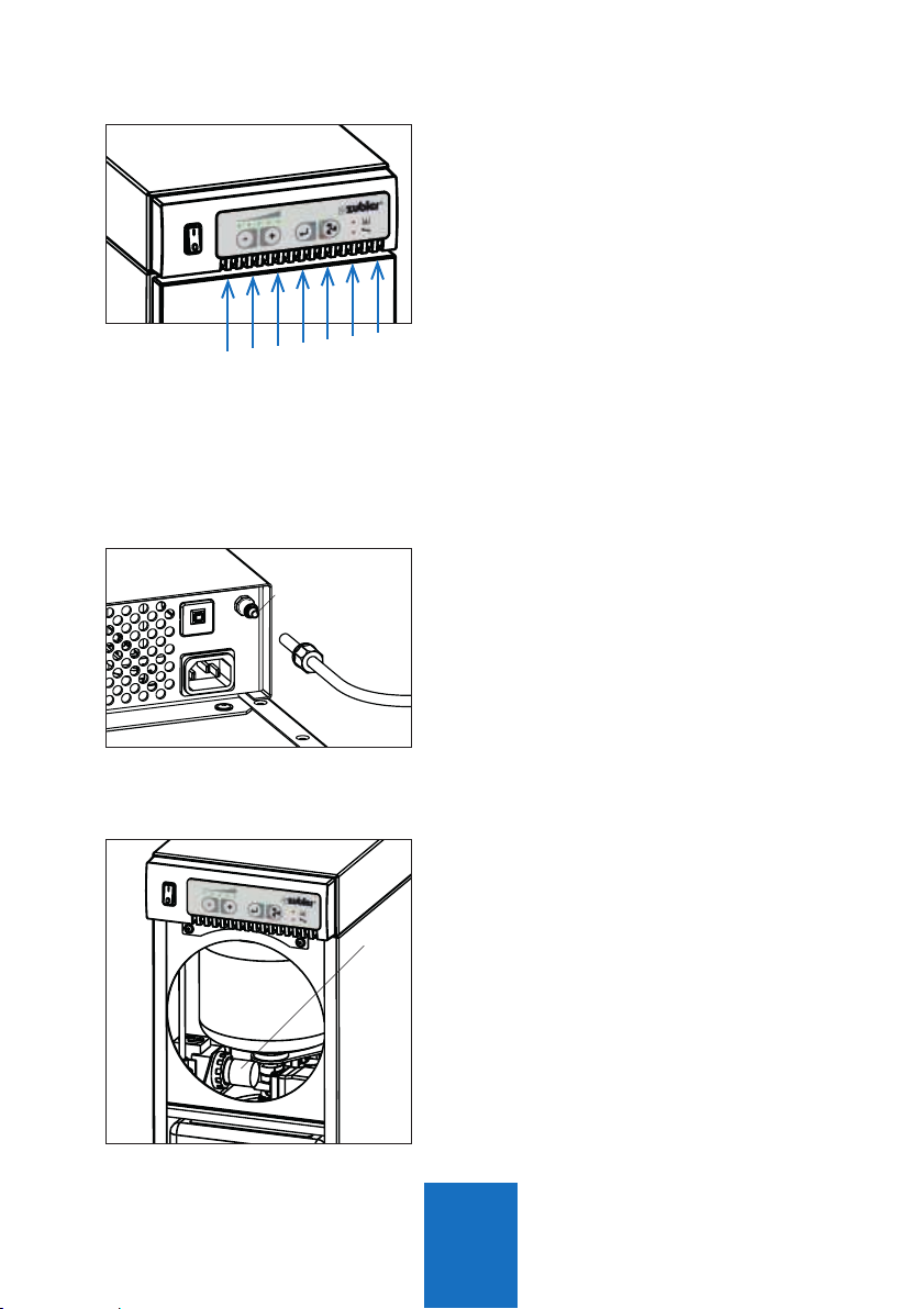
1.2.4 Compressed air
nThe suction unit Z1 PRO requires
compressed air for the filter cleaning.
The unit must not be used without
compressed air. Ensure there is a
compressed air supply available with
at min. 5 bar, free of oil and moisture.
nRemove the clamp screw of the
compressed air connector (5) and
insert the enclosed compressed air
hose (6mm). Plug the hose firmly
on the nozzle and tighten the clamp
screw. Connect the quick connector to
your compressed air supply.
nOpen the Frontdoor (Section 3.1, Fig.
14) and check if the pressure gauge
(10) on the pressure reducer shows
a pressure of 4-5 bar. The pressure
reducer is factory set and must not be
changed. Upon abnormal behaviour,
check your compressed air supply and
contact the Zubler Service.
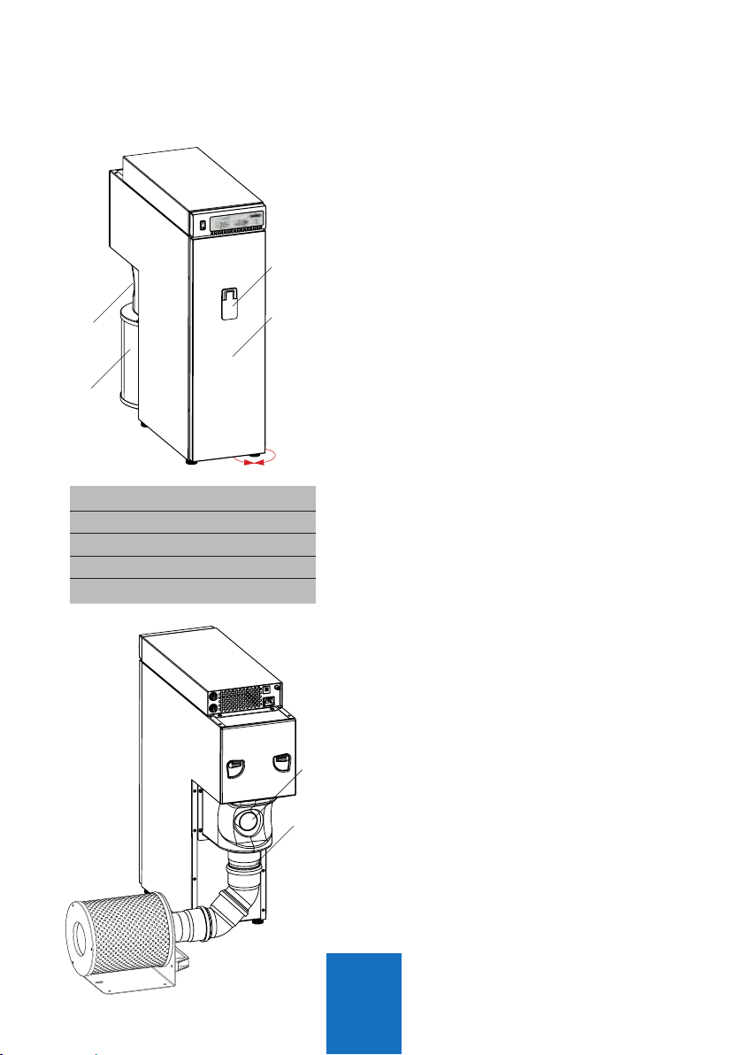
1.2.3 Furniture integration
If integrating the suction unit into cabinets
or niches the following requirements
must be taken into account:
nThe suction unit must be able to draw
cooling air from the front (Fig.4)
nThe hot exhausting air which is
released on the back of the suction
unit, must not reach the front.
Therefore it is necessary, that there is
a tight barrier surrounding the suction
unit, separating the front from the
back. Alternatively it is also possible
to guide the exhausting air away from
the suction unit, see chapter 1.2.2.
Cooling air
Fig. 5

9
7.1
7.1
7.2
4
4
8
9
55
66
Fig. 7: Connectors CAM Fig. 8: Connectors ECO
1.2.5 Mains connection
nBefore connecting the unit to the
mains power supply, check if the
voltage given on the number plate
(Fig.6) corresponds with the local
voltage.
nPlug the enclosed power cord into the
IEC C14 connector 6 and the mains
plug into a local power socket.
nThe suction unit must not be switched
ON/OFF with the mains power supply.
The mains power supply must be
connected permanently.
4 Data interface
5 Compressed air connector
6
Mains power supply (IEC C14)
7.1
Main fuse (10A)
7.2
Fuse power socket (6A)
8
Autom. power socket (IEC F)
9 24V interface
ZUBLER Gerätebau GmbH
Buchbrunnenweg 26
D-89081 Ulm
Tel. +49(0)731 1452-0 / www.zubler.de
Absauganlage
Z1-ECO PRO
Spannung 230V
Gesamtleistung max. 2000W
Absaugung max. 700W
Automatiksteckdose 1200W
Z1 ECO PRO 00-11111-22
Made in
Germany
Fig. 6

10
3
2 4
1 5
6
1.3.1
Appliances without interface (ECO only)
n
If your appliance is equipped with a IEC
plug type C14, use the enclosed IEC
power cord (C13/C14) to connect the
appliance to power socket 8.
The power cord which was enclosed
with your appliance is not needed.
n
If your appliance is equipped with a CEE
mains plug type F or C, you will need an
optional CEE-adaptor (CEE/C14) O.No.
012/00701.
The max. power rate of the appli-
ance is limited to 600W (120V)or
1200W (240V)!
1.3.2 Appliances with switching output
nIf your working appliance has a
switching output, a control cable
(special accessory) can be used to
connect to the extraction system.
Instead of C13 low temperature power
outlet 8, use the data interface 4.
1.3 Connecting the working tools

11
24V
SL230
Relais
230V
1.3.3
Appliances and machines with
230V output
nIf there is a 230 V outlet on the
machine for the extraction, use
exclusively the SL230 accessory
adaptor
1.3.3
Appliances and machines with 24V
interface (CAM only)
nIf there is a 24 V control output on the
machine for the extraction, you need a
special cable from the list on page 10.
Fig. 9
Maschine
Maschine
Maschine
Order no. 825-256SL
Special cable SL-24,
see page 10

12
Interface cable (accessory)
Ready-made adaptor cables are available for some common CAM systems
(only start signal for suction system)
Cable plug CAM system Pin-configuration
Extraction Cam
order no.
imes icore
ceramill motion
1 (+)
2 GND
4
3
825-25616
Amann-Girrbach 1 (+)
2 GND
3
4
825-25612
Vhf 4pol. 1 (+)
2 GND
1
4
825-25610
Vhf 6pol. 1 (+)
2 GND
1
6
825-25611
Sirona 1 (+)
2 GND
2
7
10
11
825-25615
Roland 1 (+)
2 GND
1
2
825-25613
without Other 1 (+)
2 GND
825-25614
1 3
2

13
2
4 5
1 3
6 7
8
24V interface:
An electrically isolated interface is
available for communication with CAM
systems and machines with PLC or 24 V
connection.
The extraction system can be coupled to
the dust-producing machine via this 8-pin
connector for the automatic start. Status
information of the extraction system can
also be received by the machine.
Input voltage and pull-up voltage for the
outputs must be provided by the machine.
A voltage of between 5 V and 24 V is
possible. Outputs are implemented as
potential-free optocoupler switched
outputs with a 120 Ohm series resistor.
PIN configuration:
Type appliance socket Amphenol 8-pin
Pin Cabel Configuration
1 white input 1 24V
2 brown GND 1
3 green input 2 24V
4 yellow GND 2
5 grey output 1
6 pink 24V CAM
7 blue output 2
8 red 24V CAM
Fig. 11:

14
Commands to the extraction system:
The various extraction power levels can
be switched, for example, in relation to
the dust level (roughing or polishing).
Filter cleaning can take place in addition
to the automatic mechanism of the
extraction system during the operating
pauses of the machine.
Input 1 Input 2 Function
0V 0V Extraction OFF
24V 0V Extraction ON with power level 1
0V 24V Carry out filter cleaning
24V 24V Extraction ON with power level 2
Output 1 Output 2 Status
0V 0V Extraction not ready / OFF
24V 0V Filter cleaning running
0V 24V Filter replacement necessary
24V 24V Extraction ready / Standby

15
C
B
A
/
R1200
Basic system requirements include
optimal particle flow, minimal noise
production and ergonomic posture
promotion.
The following criteria promote these basic
requirements and are specifically adapted
to Zubler suction systems.
nSuction funnel R1200,
nRectangular pipe R1000, R1300
nRectangular silencer R1100
nThe R1200 suction funnel (21) was
tested according to GS-IFA-M20 test
no. 1305026 for a minimum suction
performance of 20 l/s.
nSitting in the upright position in a
posture preserving ergonomically
designed chair.
nWorkpiece as close as possible to
the suction funnel 21; no dust cloud
may be visible. Trails of dust must be
drawn into the hopper.
nDirection of viewing of the workpiece
perpendicular to the protective screen.
1.4 Intake system
A Suction funnel R1200
B
Rectangular pipe R1300
C Rectangular pipe R1000
Fig. 12

16
T1 T2 T3 T4
L6
L4
L5
29
L2
L3L1
2.
L1 LED Power level display
L2 LED Bluetoothanzeige
L3 LED “ON”
L4 LED Filter
L5 LED Service
L6 LED “OFF”
T1 minus-button
T2 plus-button
T3 Return-button
T4 ON / OFF - button
29 Main switch
nThe extraction system must be
installed and connected as described
in section 1.
nSwitch on the main switch 29.
nOne ore more LEDs of the suction
level L1 are flashing.
After approx. 5s the suction unit is
ready and the last saved suction level
is displayed. (At setup level 1).
nBy pressing the ON/OFF button T4 the
suction is started with the selected
suction level L1.
nIf changeing the suction level for the
first time, the unit will take some time
to calibrate the suction volume and
compensate the flow resistances.
nFor setting and saving suction levels,
see section 2.4.
Functions
Fig. 13
2.1 Control unit
2.2 Commissioning

17
-+
T1 T2
If a dust producing appliance is connected
to the extraction system, the sensitivity
must be adjusted for an automatic start of
the extractor.
The following steps are necessary in
order to teach the appliance:
nThe appliance (max. 6A, 120V:600W,
240V:1300W) must be connected to
the socket of the extraction system.
nPreselect the handpiece speed at
which the extraction system should be
started.
nStart the appliance or the handpiece
nd keep it running.
nWhile the appliance is running, press
and hold the buttons T1 (minus) and
T2 (plus) at the same time for at
least 3 seconds until a signal sounds
and the LEDs of the display L1 light
up. The extraction system will start
running for approx. 3 seconds.
nStill keep the appliance running.
nAs soon as another signal sounds
and the LEDs of the display L1 start
flashing, switch off the appliance or
stop the handpiece immediately.
nWait until a final signal sounds and
the LEDs of the display L1 show the
preselected suction level again.
2.3 Setting up automatic operation (ECO only):

18
T1 T2
-+
T3
Stufe Suction flow
1 20 l/s
2 25 l/s
3 30 l/s
4 35 l/s
5(„turbo“) max 50 l/s
n
The suction levels 1 – 5 can be selected
with the T1 (minus) and T2 (plus) buttons.
nThe suction level shown on the display
L1 is the currently saved level with which
the extraction system switches on.
2.4 Selecting and saving suction levels
nPress the Enter button T3 to save the
new suction level
nIf the suction level is changed
without pressing the Enter button
T3, the extraction system will run the
lastsaved suction level the next time
the unit is started.
n
Suction level 5 (“Turbo mode”) is only
avail. for short time usage (factory set to
5 min.) and can therefore not be saved
in regulation mode.
n
While in “Turbo mode” the LED for
suction level 5 is flashing.
Once the time is elapsed, the suction
will fall back to the saved suction level
1-4.
n
Further adjustments can be made with
the Zubler Suction-Technology APP
(Android only).

19
If the LEDs of display L1 light up
according to the selected suction level
during suction operation, this means that
the preset air flow rate of the suction
level is also actually being provided
and the motor has not yet reached its
maximum power.
If the desired air flow rate cannot be
attained (due to flow resistance or
filter clogging), then LED lights that are
solidsignify the attainable setting, while
the flashing LEDs signify the setting
and corresponding suction loss. The
volumetric flow control device is preset
in the factory so that a warning signal
sounds and the Filter Maintenance LED
L4 lights up only at minimum suction
power.
In the advanced settings (see section 3)
it is possible to set this so that the filter
warning is given as soon as the suction
power decreases to the next lower
suction level.
nFurther adjustments can be made with
the Zubler Suction-Technology APP.
2.5 Current suction power
Example:
Suction level 3 is selected,
but the air flow rate
corresponds only to level 2.

20
T1
-
T2
+
T3 T4
T1
-
npress and hold the plus button T2
for at least 3 seconds until only the
middle LED of display L1 is lit
nthe suction time can be reduced by 1
sec per LED jump to the left with the
T1 (-) button or increased by 1 sec per
LED jump to the right with the T2 (+)
button.
npress the Enter button T3 to save the
new value
npress the fan button T4 to abort the
procedure without saving
nthe suction overrun time can be
prolonged by a further 2 sec by
repeating the procedure.
nFurther adjustments can be made with
the Zubler Suction-Technology APP
(Android only).
2.6 Setting the suction cutoff time
For the extraction of the residual dust in the air, it is possible to extend the
time the extraction system should continue to run during breaks or after the
end of dust production. The factory setting is 3 seconds.
npress and hold the minus button T1
for at least 3 seconds until only the
middle LED of display L1 is lit
nlower the switch-on threshold with the
T1 (-) button (extraction starts earlier
neasier; this is a solution if the
extraction system switches off or
doesn’t start-up immediately despite
dust being produced)
2.7 Fine tuning of the automatic operation (ECO only)
If the automatic sensitivity matching of the dust producer to the extraction
system has not yet led to an ideal result after section 1, the switch-on
threshold of the extraction can still be manually readjusted.
Other manuals for Z1 ECO
1
This manual suits for next models
1
Table of contents
Popular Scrubber manuals by other brands

Columbus
Columbus RA 66/BM 60 operating manual

diversey
diversey TASKI swingo 2100micro manual

Full Spectrum Laser
Full Spectrum Laser FSL200 user manual

Nilfisk-Advance
Nilfisk-Advance Liberty SC50 Instructions for use

floorex
floorex Beaver 250 Safety and operators manual & parts listing

HydraMaster
HydraMaster RX20 NEXTGEN 120 VAC owner's manual