Zubler V6000 User manual

www.zubler.de
V6000
Individual Vacuuming Unit
O erating instruction 11-2012
en

23
Page
Content
0. Introduction Page 4
0.1 Declaration of conformity
0.2 General hints
0.3 Regular usage
0.4 Environment
0.5 Setting up
0.5.1 Conn. the unit
0.5.2 Conn. the working tool
0.5.3 Remote switching
1. Functions Page 8
1.1 ront panel
1.2 Starting the unit
1.3 Operation
2. Adjustments Page 10
2.1 Sensitivity settings
2.2 Sensitivity adjustment
2.3 KaVo K-Control
3. Filterchange Page 12
3.1 Replacing the filter bag
3.2 Replacing the finefilter
4. Intake system Page 15
4.1 Requirements
4.2 R1200 / R1250
5. Maintenance Page 18
5.1 Replacing the Carbon Brushes
6. Troubleshooting Page 16
7. Data Page 19
7.1 Spare parts
7.2 Dimensions
7.3 Technical data
Page

3
0. Introduction
0.1 Declaration of conformity
Page Page
We, Zubler GmbH
Buchbrunnenweg 26
89081 Ulm-Jungingen /Germany
declare, that the product vacuuming unit
V6000
corresponds to the regulations of the
following directives in regard to
protective requirements
2004/108/EG EMV-Directive
2006/95/EG Low-Voltage Directive
2006/42/EG Machines Directive
Any modification not specifically
approved by us voids the validity of this
declaration.
Kurt Zubler
Managing Director

4
0.2 General hints
Dear customer,
we are pleased that you have made the decision to purchase a zubler pro-
duct and wish you a comfortable working with our equipment.
We are asking you to read the instructions carefully before putting the
installation into operation.
The vacuuming unit is especially designed to improve the dust
collection, thus protecting the operator from hazardous dusts. The auto-
matic suction volume adjustment and the two stage filter system, which
corresponds with the DIN EN 60335-2-69 standard (class M), provides an
ideal dust collection and enables an intact room air codition.
0.4 Environment
Temperature +5°C to +40°C
Air humidity max. 80% (@ 30°C)
Max. load max. 1150 W
The vacuuming unit is designed to collect dry dusts only
which are produced in dental laboratories and similar professio-
nal fields (e.g. goldsmith, hearing aid acoustician, model maker).
- The is for indoor usage only !
- Before connecting the to the mains power, check if the volta-
ge given on the number plate corresponds with the specifications of
your local mains power supply.
- or a proper usage a stable mains power supply is required with vol-
tage fluctuations below 10% of the rated value.
- Upon the occurrence of visible dust fall or a sensibly insufficient
vacuuming performance the work must be interrupted immediately
and the installation must be switched off. Inform your dealer or our
service team.
- The use is limited to persons instructed in handling and charged
with the usage.
0.3 Regular usage
PagePage
V6000
V6000
V6000
V6000

5
6
7
5
Zubler Gerätebau
numberplate
Tension XXXXXX
Number:
Fone:
2
ig. 0.1: front view
■The unit may be used standing upright
only.
■Place the unit on a sufficient stable
and even floor.
■To avoid vibrations take care that the
housing does not touch.
■The exhaust on the front must be
kept free.
1 Door lock
2 Vacuum connector
3 ront door
0.5 Setting up
Page Page
0.5.1 Connecting the unit
■Before connecting the to the
mains power, check if the voltage
given on the number plate corre-
sponds with the specifications of your
local mains power supply.
■Plug the enclosed power cord into the
low-heat-device socket (6) and con-
nect it to a local power socket.
■Connect the enclosed 40mm vacuum
hose to the vacuum connector (2) and
the other side to your intake system.
6 Sensitivity switch
7 Low-heat-device socket
8 Autom. power socket
ig. 0.2: side view
V6000
1
3

6
Mad in
G ramay
C
ZUBLER Gerätebau GmbH
Buchbrunn nw g 26
D-89081 Ulm
T l. +49(0)731 1452-0 / www.zubl r.d
Absauganlag
V6000
Spannung 230V
G samtl istung max. 1150W
Absaugung max. 700W
Automatikst ckdos 450W
V4010 00-11111-22
FP-R24
Netz
❶
❷
24V
Maschine
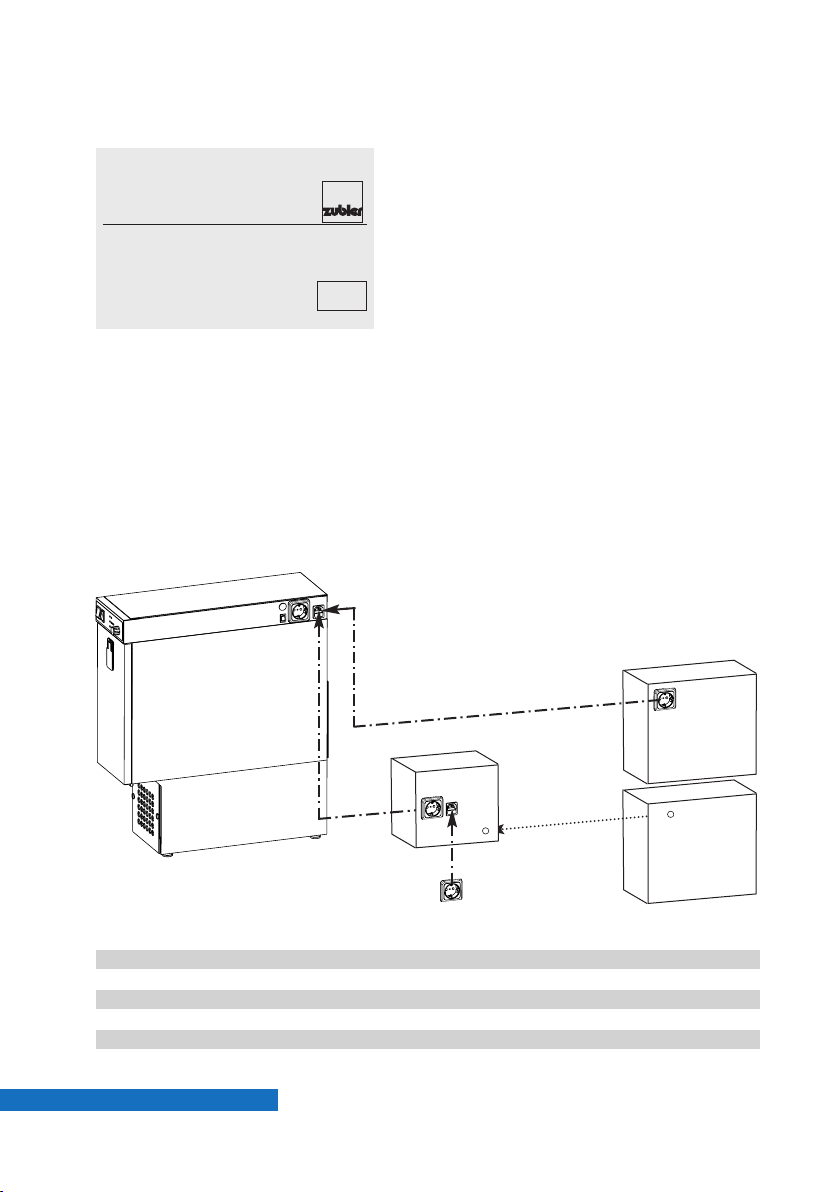
ig. 0.3: Remote switching
PagePage
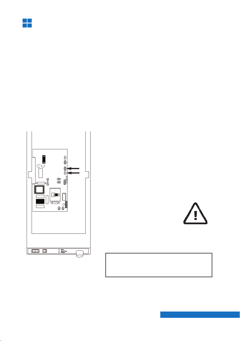
0.5.2 Connecting the technical gear
■Plug in the power cord of the working
tool (e.g. handpiece) into the autom.
power socket(7).
■The power consumption of the wor-
king tool may not exceed 450W !
■In order to make use of the automatic
operation mode the sensitivity must
be set. Choose the best matching
sensitivity setting with the sensitivity
swich (5).
■If the does not start/stop reliab-
le with one of the predefined 3 switch
positions, an internal sensitivity adjust-
ment is required (see chapter 2).
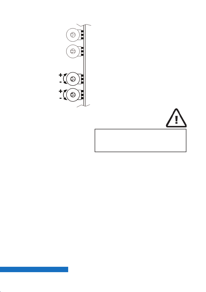
0.5.3 Remote switching (CAD/CAM)
❶If the remote machine offers a swit-
ched power socket, plug the
into the remote power socket.
❷If the remote machine offers a 24V
signal the optional P-R24 and a corre-
sponding connection cable is needed.
(see list below)
Order No.
FP-R24 825/257R24
Connection cable 24V length 2m:
SL-24 - DIN Round plug 4-pin vhf, wieland, shera 825/25600
SL-24 - DE9 D-sub-9 9-pin imes-icore, ammanngirrbach 825/25601
SL-24 - RS stereo phone jack 3,5mm roland 825/25602
SL-24 without plug other 825/25646
V6000
V6000

7
1.
O. K.
Service
Filter
Manual
Auto
14 11 1312
9 10
®
Functions
1.1 Front panel
ig. 1.1: ront panel
9 LED Service
10 LED OK
11 Autom. / Manual switch
12 LED ilter
13 Suction volume
14 Main switch
1.2 Starting the unit
■Switch the Automatic / Manual switch
(11) to Manual position to use the
manual operation mode. In this mode
the suction starts immediately after
the vacuuming unit is switched on.
■Switch the main switch (14) to ON
position to start the suction unit.
The main switch is illuminated green.
Adjust the required suction volume
with turn knob (13).
■Switch the Automatic / Manual switch
(11) to Automatic position to use the
automatic operation mode.
In this mode the suction starts
automatically after the technical gear
(e.g. handpiece) is started.
■or sensitivity adjustment see
chapter 2.
Page Page

8
1.3 peration
■The green LED “OK” (10) indicates a
normal operation.
■The red LED “Service” (9) indicates
an electric malfunctioning (e.g. worn
out carbon brushes of the motor).
■The red LED “ ilter” (12) indicates a
filled up filterbag, a clogged finefilter
cartridge or a clogged intake line.
The suction is stopped automatically
and the connected technical gear
cannot be operated.
■Switch O the suction unit with the
main switch (14). Also switch O your
technical gear to avoid an erroneous
startup after the malfunction will have
been remedied. Change the filterbag
and / or the fine filter cartridge and
check the intake line.
■or filterchange see chapter 3.
PagePage

99
B
A
2. Adjustments
ig. 2.1
2.1 Sensitivity settings
Plug in the power cord of the technical gear (e.g. handpiece) into the
automatic socket (27) ( ig.0.2) of the suction unit. The max. load may not
exceed 450W !
Use one of the three predefined sensitivity settings of the external
sensitivity switch (25). The order of the switch positions is as follows :
I: Low sensitivity (Schick CN, KaVo S )
0: Medium sensitivity (W+H Elco 2)
II: High sensitivity (Schick C2 & SM78, KaVo K9, K10)
If your working tool does not work reliable with one of the three sensitivity
switch positions, an internal sensitivity adjustment is necessary.
■Remove the screw which is holding
the top cover.
■Pull the cover carefully backwards and
take it off.
■Remove the ground wire and put the
cover aside.
2.2 Sensitivity adjustment
Attention!
Pull mains plug before opening the
unit!
Page Page

10
■If the external sensitivity switch (5)
( ig. 0.2) is on level II the suction unit
will run continuously, even if the
handpiece is not actuated.
(Sensitivity too high)
■On level 0 the unit will not start with
the lowest rotation speed 5000 rpm.
(Sensitivity too low)
■Switch externally to level 0 and
increase the sensitivity by turning
rheostat B to plus (+) until the unit
starts running.
■Alternatively you may also switch
externally to level II and decrease the
sensitivity by turning the rheostat to
minus (-) until the unit stops running.
2.3 KaVo K-Control
■The adjustment is performed by turning
rheostat B on the PC-board into the
needed direction.
■If the suction unit does not shut O
although the handpiece is not actuated,
the sensitivity is too high. Turn rheostat
B to minus (- = CCW).
■If in a reversed case the suction unit
does not start after actuating the hand-
piece, the sensitivity is too low. Turn
rheostat B to plus (+ = CW).
Take care that neither hoses nor
wires inside the electronic room are
pinched or twisted.
ig. 2.2
B- Sensitivity
A- Damping
PagePage

11
3.
ig. 3.1
Filterchange
■Switch off the unit with the main
switch (14) and open the door lock (1).
■Open the front door (3) and pull out
the filter cage (16).
3.1 Replacing the filterbag
Perform a filter change only with an
appropriate protective equipment.
(Gloves, breathing mask)
16 ilter cage
17 ilter bag
Page Page
16
17

12
Store and eliminate contaminated
filters immediately after withdrawal
in a dust-tight lockable plastic bag.
Activated carbon filters must be
changed periodically. The period is
dependant on type, amount and
concentration of the vacuumed
fumes and gases.
ig. 3.2
ig. 3.3
■Open the cage door by unlocking the
2 fasteners.
■Pull the gasket off the nozzle and take
out the filter bag (17).
■Close the opening with the adhesive foil.
■Store the filter bag immediately in a
dust-tight plastic bag and dispose the
filter bag according to your local
guidelines.
■Insert a new filter bag and slide the
gasket over the nozzle.
■Close the filter cage and slide it back
into the unit. Close the front door (3)
and lock it again.
PagePage

13
20
19
18
The is additionally equipped with a
finefilter cartridge.
Its function is to collect fine dusts, which
volatilizes through the filter bag or are set
free during the replacement.
If the red LED “ ilter” (12) ( ig.1.1) is still
lighted although the filter bag was already
replaced or if the change intervals of the fil-
terbag get sensibly shorter, the cause is a
clogged finefilter cartridge.
18 inefilter cartridge
19 inefilter cover
20 Exhaust plate
3.2 Replacing the finefilter
■Switch off the unit with the main switch
(14).
■To access the back side of the
you may need to remove all connections
and pull out the unit.
■Open the finefilter cover (19) by remo-
ving the 3 philips screws.
■Take out the finefilter cartridge by twi-
sting it upwards.
■Store the cartridge immediately in a
dust-tight plastic bag and dispose the fil-
ter bag according to your local guideli-
nes.
■Insert a new finefilter cartridge and close
the finefilter cover with the 3 philips
screws.
■Reconnect the vacuum hose and all
ectrical connections.
Activated carbon filter (optional)
■The can be additionaly equipped
with an activated carbon filter which
Replaces the exhaust plate (20).
Remove the plate by turning the 2
screws into horizontal position.
ig. 3.4
ig. 3.5
Page Page
V6000
V6000
V6000

14
4. Intake system
Basic requirements upon an intake sytem
are beside an optimal dirt collection the
avoidance of disturbing flow noises and the
encouragement of an ergonomic working
position.
These properties can only be granted with
an intake system especially matching the
vacuuming unit consisting of
■Suction funnel R1200
■Suction funnel R1250 (ceramics, gold)
■Rectangular pipe R1000, R1300
■Silencer R1100.
4.1 Requirements
4.2 R1200/R1250
ig. 4.1 ■Upright seat position on an
appropriate seat furniture.
■Workpiece as close to the suction
funnel as possible, no dust fog may
be visible. Dust streaks must be
pulled into the funnel.
■Viewing direction onto the workpiece
vertical to the safety glass.
PagePage

15
5.
B
B
A
ig. 5.1
ig. 5.2
■
Open the finefilter cover and the motor
cover by removing the 7 phillips screws
(A+B) to get access to the motor.
■
Do NOT remove the motor !
■
Unplug the wires from the brush holders
and pull out the brushes while pressing
down the metal latch.
■
Insert the new brushes until they lock
and reconnect the wires.
Always change B TH carbon brushes !
Maintenance
Before cleaning and servicing the gear and also before replacing
spare parts the suction unit must be separated from the mains supply !
Wipe off any outer soiling with a mere moist cloth, protect the
suction unit from water penetration !
Maintenance works on electrical parts of the unit must solely be
carried out by expert personnel or by persons having been trained.
We recommend to verify the suction technique once per annum or
to let an instructed person do this check with regard to tightness
against dust and to functioning.
5.1 Replacing the Carbon Brushes
Page Page

16
6.
Fehlererkennung Ursache Abhilfe
LED „ ilter“ illumi-
nated
Due to a filled up
filter bag and/or a
clogged fine filter
as well as a clog-
ged suction line,
the minimum suc-
tion performance
can no longer be
granted.
The internal elec-
tronics interrupts
the vacuuming
operation.
Change the main
filter (see chapter
"Main filter
change"). If the
indication does not
extinguish also
change the fine fil-
ter (see chapter
"fine filter
change"). If the
indicator light will
still not extinguish
check the suction
line, starting with
the intake system,
with regard to clog
ups.
Troubleshooting
LED „Service“ illu-
minated
An electrical dis-
turbance mostly
caused by worn
out carbon brus-
hes of the suction
motor after an
operating period
of about 2 – 3
years.
Replace the used
carbon brushes
(instructions will
be sent with the
replacement brus-
hes).
Carbon brushes
must and can be
replaced only
once. If the collec-
tor is already worn
out, only an
exchange of the
motor can create
remedy.
Page

17
Fehlererkennung Ursache Abhilfe
Suction does not
start (main switch
(14) is NOT illumina-
ted)
No mains supply
or mains switch
not switched on.
use burnt-out
due to overchar-
ging.
Check the mains
connection. Switch
the main switch
(14) into "On" posi-
tion, the main
switch is illumina-
ted green. Check
the fuse inside the
cold gear socket
and also the brea-
ker on the installa-
tion side.
Suction does not
start in "Automatic“–
mode
Sensitivity level of
the automatic sok-
ket is too low.
Select a different
sensitivity switch
position
(see chapter
"Setting-up").
Suction does not
switch off in
"Automatic“-mode
(Suction runs conti-
nuously)
Sensitivity level of
the automatic sok-
ket is too high;
Spark discharge
due to renewed
carbon brushes.
Select a different
sensitivity switch
position (see chap-
ter "Setting-up").
New carbon brus-
hes need a run-in
period of about 2 –
3 hours.
Page
Please ask your local dealer or call our service team under
+49 (0)731 1452-58.
You can reach us from :
Mo – Thu 8-17h,
Fr 8-13h
For faster processing keep model type and serial number ready
at hand. You can find these data on the type label near the auto-
matic socket.

18
7.
7.1 Spare parts:
Page
Data
Pos. Name Order No. Pos. Name Order No.
1.0 Filter housing 570/2202 1.4.3 Filter bag, feeded 556/035
1.0.1 Autom. power socket 012/005 1.5 Electronic housing 570/2375
Socket frame 012/0051 Front panel 020/006
1.0.2 Sensitivity switch 019/0011 1.5.1 Main switch I/O 019/0061
1.0.3 low-heat-device socket 012/0031 1.5.2 urn knob 022/004
1.0.4 Main fuse 028/0125 1.5.3 Potentiometer 752/041
1.0.5 Vacuum connector 563/0804 1.5.4 LED board 752/040
1.0.6 Vacuum sensor 752/0103 1.5.5 Mode switch 019/0082
1.0.7 Cage sealing 557/118 1.6 Mainboard 753/0347
1.1 finefilter cover 570/2367 1.7 op cover 570/2365
1.2 finefilter cartridge 556/019 2.0 Motor cover 570/2423
1.3 Front door 563/082 2.0.1 Foot 558/007
1.3.1 Hinge right 567/001 2.0.2 Exhaust Foam 549/0037
1.3.2 Hinge left 567/002 2.0.3 Exhaust cover 570/2371
1.3.3 Door lock 570/0398 2.1 Motor package 752/310
1.3.4 Door sealing 557/1211 2.1.1 Carbon brushes 037/10240
1.3.5 Distance piece 570/2497 2.1.2 Blower motor K71 450/008
1.4 Filter cage 752/103 2.1.3 Motor ring 558/130
1.4.1 Filter nozzle 563/0041 2.1.4 Motor package sealing 557/059
1.4.2 Cage fastener 570/1052 2.2 Noise damper 549/009

19
7.3 Technical data:
Width 200 mm
Height 680 mm
Depth 610 mm
Weight 31 kg
Tension (see number plate) 100V / 115V 230V / 240V
50-60 Hz 50-60 Hz
using
main fuse T10A T6,3A
autom. socket (internal) T4 A T2 A
Total power consumption max.1150 W
Nominal power suction unit max. 700 W
autom. socket max. 450 W
ilterbag :
iltersurface 0,4 m2
Dust capacity approx. 4 kg
inefilter cartridge :
iltersurface 0,7 m2
Volume flow 90 -135m3/h
Low pressure 8.000-14.000 Pa
Sound level 52-61 dB(A)
7.2 Dimensions:
ig. 7.1
Page

20 C
Bxxxxx / 11-2012
V6000
www.zubler.de
Zubler Gerätebau GmbH
Buchbrunnenweg 26
D-89081 Ulm-Jungingen
B- - en 48-2012
technical changes without notice!
en
Table of contents
Other Zubler Vacuum Cleaner manuals