manuals.online logo
Brands
  1. Home
  2. •
  3. Brands
  4. •
  5. Zuchetti
  6. •
  7. Plumbing Product
  8. •
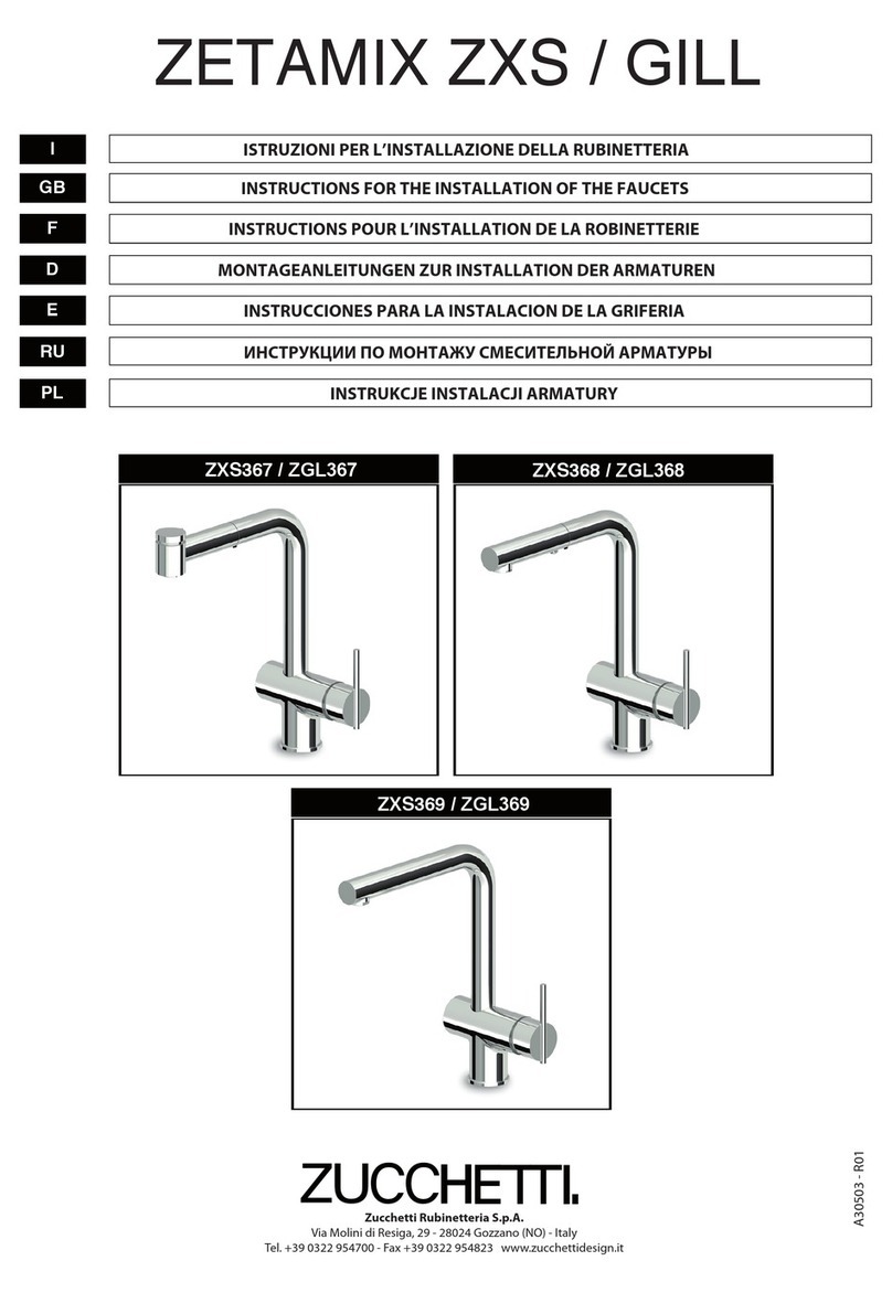
  9. Zuchetti Bellagio ZB2422 Parts list manual

Zuchetti Bellagio ZB2422 Parts list manual

INSTALLAZIONE / INSTALLATION / УСТАНОВКА
MOD. 1
I - Predisporre la piantana 1, inserendo il dado 2, la ranella 3e la guarnizione 4.
GB - Prepare the side valve 1, by inserting the nut 2, the washer 3and the seal 4.
F- Préparer la pièce de raccordement 1, en insérant l’écrou 2, la rondelle 3et le joint 4.
D- Die Mutter 2, die U-Scheibe 3und die Dichtung 4 über das Seitenventil 1führen.
E- Ponga el tubo vertical 1, insertando la tuerca 2, la arandela 3y la junta 4.
RU - Соедините боковой клапан 1сгайкой 2, кольцом 3ипрокладкой 4.
PL -Na zawór 1założyćnakrętkę2, podkładkę3i uszczelkę4.
Inserire (dal basso) la piantana 1 nel foro del sanitario. Infilare sull’asta della piantana la guarnizione 5ed il collare 6,
avvitando quest’ultimo sulla piantana.
Insert (from below) the side valve 1in the hole of the basin. Insert in the side valve rod the seal 5and the collar 6, by
tightening the latter to the side valve.
Introduire (par le bas) la pièce de raccordement 1dans le trou du sanitaire. Introduire sur la tige de la pièce de raccorde-
ment le joint 5et le collier 6, en serrant ce dernier sur la pièce de raccordement.
Das Seitenventil 1(von unten) in die Öffnung des Sanitärobjektes einführen. Die Dichtung 5und den Kragen 6auf die
Stange des Seitenventils führen und den Kragen an dem Seitenventil verschrauben.
Inserte (desde abajo) el tubo vertical 1en el agujero del sanitario. Enfile en la varilla del tubo vertical la junta 5y la
abrazadera 6, enroscando ésta último al tubo vertical.
Вставьте снизу боковой клапан 1вотверстие вумывальнике. На шток бокового клапана оденьте прокладку 5
ипривинтите кольцо 6.
Umieścićzawór 1w otworze ceramiki, wkładając go od spodu. Na trzpieńzaworu założyćuszczelkę5i dokręcićpierścień
6.
Introdurre (completamente) nel collare 6, il raccordo svitatore 7.
Insert (completely) in the collar 6, the unscrewing joint 7.
Introduire (complètement) sur le collier 6, le raccord dévisseur 7.
Den Ausschraubanschluss 7 über den Kragen 6führen.
Introduzca (completamente) la abrazadera 6, el racor desenroscador 7.
Установите (до конца) винтовое соединение 7на кольцо 6.
Na pierścień6nałożyć(do końca) złączkę7.
Avvitare il piantone 8sul collare. Le basi dei 3 elementi devono risultare allineate fra loro. Per eventuali regolazioni ruota-
re leggermente la piantana.
Tighten the flange 8 to the collar. The bases of the three elements should result aligned. For further regulations, turn a
little bit the side valve.
Serrer la rosace 8 sur le collier. Les bases de trois éléments doivent résulter alignées parmi eux. Pour des éventuelles
régulations pivoter un peu la pièce de raccordement.
Die kleine Säule 8an dem Kragen verschrauben. Die Basis der 3 Elemente müssen miteinander ausgerichtet sein. Das
Seitenventil für eventuelle Regelungen leicht drehen.
Enrosque el montura 8a la abrazadera. Las bases de los 3 elementos deben quedar alineadas entre sí. Para eventuales
regulados gire ligeramente el tubo vertical.
Привинтите стойку 8ккольцу. Основания всех трех элементов должны быть параллельными. При
необходимости осуществите регулировку поворотом бокового клапана.
Przymocowaćdo pierścienia rozetę8. Podstawy wszystkich trzech elementów musząznajdowaćsięw jednej linii. Jeśli
elementy nie sądokładnie wyrównane należy delikatnie poruszyćzaworem.
1
6
2
6
7
3
4
8
1
1
3 4
2
5
INSTALLAZIONE / INSTALLATION / УСТАНОВКА
MOD. 1
I - Inserire a pressione la maniglia 9sull’asta della piantana. Serrare con una chiave da 32 mm il dado 2.
GB - Insert with pressure the handle 9 in the side valve rod. Tighten the nut 2 with a 32 mm Key.
F- Introduire à pression la manette 9 sur la tige de la pièce de raccordement. Serrer avec une clé de 32 mm l’écrou
2.
D- Den Griff 9auf die Stange des Seitenventils drücken und die Überwurfmutter mittels eines Schlüssels 32 mm
fest schrauben.
E- Inserte a presión la manilla 9en la varilla del tubo vertical. Apriete con una llave da 32 mm la tuerca 2.
RU - Сусилием установите рычаг 9на шток бокового клапана. Гайку 2затяните ключом на 32 мм.
PL - Wcisnąć na trzpieńzaworu pokrętło 9. Dokręcićdo oporu nakrętkę2za pomocąklucza 32 mm.
Avvitare i flessibili 10 e il perno filettato 11 sulla bocca 12. Inserire la guarnizione 13 che dovrà posizionarsi fra la bocca
ed il sanitario.
Tighten the flexible pipes 10 and the threaded pin 11 to the spout 12.Insert the seal 13 that will have to take position
between the spout and the basin.
Serrer les flexibles 10 et le pivot fileté 11 sur le bec 12. Introduire le joint 13 qui devrait se positionner entre le bec et le
sanitaire.
Die Schläuche 10 und den Gewindestift 11 an dem Auslauf 12 verschrauben. Die Dichtung 13 einführen und dabei be-
achten, dass sie zwischen dem Auslauf und dem Sanitärobjekt angesetzt wird.
Enrosque los flexibles 10 y el perno roscado 11 a la boca 12. Inserte la junta 13 que deberá situarse entre la boca y el
sanitario.
Привинтите гибкую подводку 10 ирезьбовой стержень 11 кизливу 12. Установите прокладку 13, которая
будет находиться между изливом иумывальником.
Dokręcićwężyki 10 oraz gwintowany sworzeń11 do wylewki 12. Pomiędzy wylewkąa ceramikąumieścićuszczelkę13.
Fissare la bocca al sanitario utilizzando il relativo kit: guarnizione 14, ranella 15, forcella 16 e serrando il dado 17 sul
perno filettato (chiave da 12 mm).
Fix the spout to the basin by using its kit: the seal 14, the washer 15, the fork 16 and by tightening the nut 17 to the
threaded pins (12 mm key).
Fixer le bec au sanitaire en employant son propre kit : le joint 14, la rondelle 15, la fourche 16 et en serrant l’écrou 17 sur
le pivot fileté (clé de 12 mm).
Den Auslauf an dem Sanitärobjekt mittels des beigepackten Befestigungssets befestigen: Dichtung 14, U-Scheibe 15,
Schnellbefestigung 16.Die Überwurfmutter 17 an dem Gewindestift mittels eines Schlüssels 12 mm festschrauben.
Fije la boca al sanitario utilizando el kit preparado para ello: junta 14, arandela 15, horquilla 16 y atornillando la tuerca 17
al perno roscado (llave de 12 mm).
Закрепите излив на умывальнике при помощи следующего набора: прокладка 14, уплотнительное кольцо 15,
вилка 16 игайка 17, которую следует затянуть ключом на 12 мм на резьбовом стержне.
Umieścićwylewkęw otworze ceramiki, po czym przymocowaćjąna uszczelce 14, używając podkładki 15, metalowej
podkładki 16 i nakrętki 17, którąnależy wkręcićdo oporu na gwintowany sworzeń(klucz 12 mm).
Inserire l’asta scarico 18 nel foro superiore della bocca. Collegare i flessibili 10 alle piantane, interponendo le dovute
guarnizioni 19.
Insert the pop up waste rod 18 in the upper hole of the spout. Connect the two flexible pipes 10 to the side valve, by
inserting the necessary seals 19.
Introduire la tige du vidage 18 dans le trou supérieur du bec. Connecter les flexibles 10 aux pièces de raccordement, en
introduisant les joints nécessaires 19.
Die Zugstange 18 in die obere Auslaufsöffnung einführen. Die Schläuche 10 mit den Seitenventilen verbinden und dazwi-
schen die dafür vorgesehenen Dichtungen 19 anbringen.
Inserte la varilla de descarga 18 en el orificio superior de la boca. Conecte los flexibles 10 a los tubos verticales,
interponiendo las debidas juntas 19.
Вставьте штангу управления сливом 18 вверхнее отверстие излива. Подсоедините гибкую подводку 10 к
боковым клапанам, вставив необходимые прокладки 19.
W górny otwór wylewki wsunąć cięgno korka automatycznego 18. Podłączyćwężyki 10 do zaworów, umieszczając w
wężykach niezbędne uszczelki 19.
5
9
2
6
10
11
13
12
7
14
16
17
15
8
18
10 19
INSTALLAZIONE / INSTALLATION / УСТАНОВКА
MOD. 3
I - Avvitare i raccordi eccentrici 1 (fino alla fine del filetto), sulle tubazioni di alimentazione. Servirsi dell’apposita
dima 2, per ottenere l’interasse dovuto. Verificare la perpendicolarità.
GB - Screw the S-tail pieces 1(till the end of the thread) on the water inlet pipes in the wall. Use the paper template 2
that you find in the box to obtain the necessary inter axes. Verify that it is perpendicular.
F- Visser les raccords excentriques 1(jusqu’au fond du filet), sur les tuyauteries d’alimentation. Employer le gabarit
en papier 2que vous trouvez dans la confection pour obtenir l’entre-axes nécessaire. Vérifier la perpendicularité.
D- Die exzentrischen Anschlüsse 1 (bis zum Ende des Gewindes) auf die Zufuhrleitungen schrauben. Die dafür vor
ge sehene Schablone verwenden, um den nötigen Achsenabstand zu erhalten. Die lotrechte Lage überprüfen.
E- Enroscar los racores excéntricos 1(hasta el final de la rosca), a las tuberías de alimentación. Servirse del patrón
2, para conseguir el intereje debido. Verificar la perpendicularidad.
RU -Привинтите эксцентрические соединения 1(до конца резьбы) кподводке. Чтобы получилось
необходимое межосевое расстояние, используйте прилагаемый шаблон 2. Убедитесь, что детали
перпендикулярны.
PL -Nakręcićzłączki mimośrodowe 1(do końca gwintu) na rurach doprowadzających wodę. Użyćbędącego na
wyposażeniu papierowego wzornika 2, aby otrzymaćodpowiedni rozstaw. Sprawdzićpoziom.
Allineare il gruppo vasca davanti ai raccordi eccentrici. Inserire le sedi 3del gruppo vasca nei raccordi 1, spingendo il
pezzo fino al contatto con le piastrelle.
Align the bath shower in front of the S-tail pieces. Insert the housings 3of the bath shower in the connections 1, by push-
ing the piece until it touches the wall.
Aligner le bain douche devant les raccords excentriques. Introduire les sièges 3du bain douche dans les raccords 1, en
poussant le pièce jusqu’au contact avec le carrelage.
Die Wannenarmatur vor die exzentrischen Anschlüsse ausrichten. Die Sitze 3der Wannenarmatur in die exzentrischen
Anschlüsse 1einsetzen, und das Stück bis zur Berührung mit den Fliesen einschieben.
Alinear el grupo de la bañera ante los racores excéntricos. Insertar los huecos 3del grupo de la bañera en los racores 1,
empujando la pieza hasta su contacto con las baldosas.
Установите смеситель для ванны посадочными местами 3всоединения 1сусилием до контакта сплиткой.
Ustawićrówno baterięwannowo-natryskowąprzed złączkami mimośrodowymi. Umieścićgniazda baterii 3w złączkach 1i
docisnąć bateriędo ściany.
Fissare il gruppo vasca ai raccordi eccentrici, servendosi degli appositi grani 4(chiave a brugola da 3 mm), che vanno
avvitati nei fori sotto i rosoni 5. Dal contatto, fare ancora 180° (mezzo giro di chiave).
Fix the bath shower to the S-tail pieces, by using the appropriate grub screws 4(3 mm Allen Key) that have to be screwed
in the holes under the flanges 5. After the contact, do again 180° (half key tour).
Fixer le bain douche aux raccords excentriques, en employant les grains appropriés 4(clé hexagonale de 3 mm) qui
doivent être vissés dans les trous sous les rosaces 5. Après le contact, faire encore 180° (demi tour de clé).
Die Wannenarmatur an die exzentrischen Anschlüsse befestigen, dazu die entsprechenden Stifte 4 (3 mm Inbusschlüs-
sel) verwenden, die in die Bohrungen unterhalb der Rosetten 5eingeschraubt werden. Nach der Berührung nochmals um
180° drehen (halbe Schlüsseldrehung).
Fijar el grupo de la bañera a los racores excéntricos, sirviéndose de los tornillos prisioneros adecuados 4(llave allen de 3
mm), que deben ser atornillados en los orificios bajo los rosetones 5. Después del contacto, hacer de nuevo 180° (media
vuelta de llave).
Установите винты 4вотверстия под накладками 5(шестигранным ключом на 3 мм), тем самым закрепите смеситель для
ванны на эксцентрических соединениях. От момента контакта заверните винты еще на 180º (пол-оборота ключа).
Zamocowaćbaterięwannowo-natryskowądo złączek mimośrodowych przy pomocy kołków mocujących 4(klucz
imbusowy 3 mm). Kołki wsunąć do otworów znajdujących sięna spodzie rozet 5i dokręcić. Po stwierdzeniu oporu
wykonaćjeszcze obrót klucza o 180° (półobrotu).
3
4
5
3
1
2
2
1
1
Sostituzione vitone:staccare il gruppo vasca svitando il grano 4(chiave a brugola da 3 mm). Estrarre la maniglia 6montata a pressione,
tirando con forza. Svitare il vitone - sede 7(chiave a brugola da 9 mm). Avvitare il nuovo ricambio avendo cura di non danneggiare gli o-r. di
tenuta 8. Rimontare in senso inverso.
Headwork substitution: remove the bath shower by unscrewing the grub screw 4 (3 mm Allen key). Remove the handle 6fixed with pres-
sure, by pulling strongly. Unscrew the headwork - housing 7(9 mm Ak). Screw the new piece by paying attention not to damage the o-r 8.
Reassemble in the opposite direction.
Remplacement de la tête: détacher le bain douche en dévissant le grain 4 (clé hexagonale de 3 mm) Extraire la croisillon 6fixée à pression,
en tirant avec force. Dévisser la tête - siège 7(clé hexagonale de 9 mm). Visser le nouveau pièce faisant attention à ne pas abîmer les O-ring
de tenue 8. Remonter dans le sens contraire.
Schraube-Austausch: den Stift 4(3 mm Inbusschlüssel) losschrauben und die Wannenarmatur entfernen. Den eingedrückten Griff 6 durch
festes Ziehen herausnehmen. Die Schraube - Sitz 7(9 mm Inbusschlüssel) losschrauben. Den Ersatzteil einschrauben, dabei darauf achten,
dass die O-Ringe 8 nicht beschädigt werden. In umgekehrter Reihenfolge wieder montieren.
6
4 7
8
8
4
Sustitución de la cabeza: quitar el grupo de la bañera desatornillando el tornillo prisionero 4(llave allen de 3 mm). Extraer la manilla 6montada a presión, tirando con fuerza. Desatornillar el tornillo
prisionero - hueco 7(llave allen de 9 mm). Atornillar el nuevo recambio teniendo cuidado de no dañar los o-ring de cierre 8. Volver a montar en sentido contrario.
Замена головного узла: отвинтите установочный винт 4(шестигранный ключ 3мм). Снимите ручку 6, она устанавливается давлением – примените усилие. Отвинтите головной
узел – посадочное место 7(шестигранный ключ 9 мм). Осторожно привинтите новую запчасть, чтобы не повредить уплотнения 8. Произведите сборку как указано выше, но в
обратной последовательности.
Wymiana głowicy: zdjąć baterięwannowo-natryskowąwykręcając kołki mocujące 4(klucz imbusowy 3 mm). Zdjąć mocowane wciskowo pokrętło 6, silnie pociągając. Wykręcićgłowicę7(klucz
imbusowy 9 mm). Wkręcićnowągłowicęzwracając przy tym uwagę, aby nie uszkodzićuszczelek o-ring 8. Złożyćpozostałe części, w kolejności odwrotnej niżpodczas demontażu.
INSTALLAZIONE / INSTALLATION / УСТАНОВКА
MOD. 4
I - Avvitare il perno filettato 1 sul corpo del monoforo / monocomando 2. Inserire l’asta di scarico 3nell’apposito
foro.
GB - Screw the threaded pin 1on the body of the single hole / single lever tap 2. Insert the pop-up waste rod 3in the
appropriate hole.
F- Visser le pivot fileté 1sur le corps du mélangeur monotrou / mitigeur 2. Introduire la tirette de vidage 3dans le
trou fait exprès.
D- Den Gewindestift 1mit dem Körper der 1.Loch-Armatur/des Einhebelmischers 2 verschrauben. Die Zugstange 3
in die dafür vorgesehene Öffnung einführen.
E- Atornillar el perno con filete 1sobre el cuerpo del monobloc / monomando 2. Insertar la varilla desague 3en su
agujero.
RU - Привинтите резьбовой стержень 1ккорпусу однорычажного смесителя для одного монтажного
отверстия 2. Вставьте штангу управления сливом 3всоответствующее отверстие.
PL -Przykręcićgwintowany sworzeń1do korpusu baterii 2. Wsunąć cięgno korka automatycznego 3do
przygotowanego otworu.
Avvitare i flessibili di alimentazione 4sul corpo del monoforo / monocomando ed inserire sul fondo dello stesso, nell’appo-
sita sede, la guarnizione 5.
Screw the flexible supply pipes 4onto the main part of the single-hole / single lever tap and insert the shaped seal 5on its
base, in the appropriate housing.
Visser les flexibles de raccordement 4sur le corps du mélangeur monotrou / mitigeur et introduire sur le fond de celui-ci
le joint façonné 5, dans le siège prévu à cet effet.
Die Anschlussschläuche 4an der Einlocarmatur verschrauben, dann den O-Ring 5, in die Nut am Armaturenkörper einle-
gen.
Atornillar los flexibles de alimentación 4en el cuerpo del monobloc / mezclador e insertar en el fondo del mismo, en el
asiento correspondiente, la guarnición perfilada 5.
Привинтите шланги подводки 4ккорпусу однорычажного смесителя для одного монтажного отверстия ив
соответствующее посадочное место снизу установите прокладку 5.
Przykręcićwężyki podłączeniowe 4do korpusu baterii i umieścićpod korpusem, w odpowiednim miejscu, profilowaną
uszczelkę5.
1
1
2
3
Posizionare il rubinetto in corrispondenza del foro del sanitario (min. 34 mm - max. 39 mm) e procedere con il fissaggio
mediante la guarnizione sagomata 6, forcella metallica 7e dado 8, che va avvitato sul perno filettato 1(chiave da 12
mm).
Place the tap at the hole of the sanitaryware appliance (min. 34 mm - max 39 mm) and go on with the fixing by using the
seal 6, the metal fork 7and the nut 8, that has to be screwed on the threaded pin 1(12 mm spanner).
Poser le robinet en correspondance du trou du sanitaire (min. 34 mm - max 39 mm) et continuer avec le fixage à l’aide
d’une 6, fourche 7 et d’un écrou 8, qui doit être serré sur le pivot fileté 1(clé de 12 mm).
Die Armaturen am Loch der Sanitäreinrichtung (min. 34 mm - max. 39 mm) einführen. Die Befestigung erfolgt mit der
Formdichtung 6, der Gabelhalterung aus Metall 7und der Mutter 8, die am Gewindezapfen 1(Schlüssel 12 mm) einge-
schraubt wird.
Colocar el grifo en correspondencia con el agujero del sanitario (min. 34 mm - máx. 39 mm) y proceder a su fijación
mediante la empaquetadura perfilada 6, horquilla metálica 7y tuerca 8, que va apretada al perno roscado 1(llave de 12
mm).
Установите смеситель вотверстие вумывальнике (мин 34 мм – макс 39 мм) ипроизведите монтаж при
помощи фигурного уплотнения 6, металлической вилки 7игайки 8, последняя прикручивается крезьбовому
стержню 1 (ключ 12 мм).
Umieścićbaterięna otworze ceramiki (min. 34 mm – maks. 39 mm) po czym przymocowaćjąna uszczelce 6, używając
metalowej podkładki 7i nakrętki 8, którąnależy wkręcićdo oporu na gwintowany sworzeń1 (klucz 12 mm).
3
8
7
6
1
2
5
4
INSTALLAZIONE / INSTALLATION / УСТАНОВКА
MOD. 5
I - Allacciare il corpo incasso alle tubature seguendo le indicazioni presenti sul pezzo (HOT, COLD). Incassare il
corpo in modo che la superficie delle piastrelle venga a trovarsi tra i riferimenti MIN e MAX presenti sulla prote
zione.
GB - Connect the flush-mounted casing to the piping according to the instructions provided on the component itself
(HOT, COLD). Install the casing so that the surface of the tiles comes between the MIN and MAX references on
the protecttive cover.
F- Raccorder le corps à emboîtement aux tubes en suivant les indications présentes sur la pièce (HOT, COLD). Emboîter le corps de
façon à ce que la surface des plaques soit placée entre les références MIN et MAX situées sur la protection.
D- Das UP-Element an den Rohrleitungen anschließen, dabei die Angaben am Teil (HOT, COLD) befolgen. Das Gehäuse so ein
bauen, dass sich die Fliesenoberfläche zwischen den an der Sicherung befindlichen Markierungen MIN und MAX befindet.
E- Empalmar el cuerpo de encaje a las tuberías siguiendo las indicaciones que se hallan en la pieza (HOT, COLD). Encajar el cuerpo
de forma que la superficie de las plaquitas venga a encontrarse entre las referencias MIN y MAX presentes en la protección.
RU -Установите подводку квстраиваемой части всоответствии снадписями (HOT- горячая вода, COLD-холодная
вода). Установите внишу корпус смесителя так, чтобы поверхность плитки проходила между метками MIN и
MAX на защитном колпачке смесителя.
PL -Podłączyćkorpus do rur zgodnie ze wskazaniami umieszczonymi na korpusie (HOT, COLD). Umieścićkorpus w ścianie
zwracając uwagę, aby po wykończeniu powierzchnia ściany znalazła sięw przedziale Min i Max zaznaczonym na plastikowej
osłonie.
Procedere con l’installazione delle parti esterne successivamente all’applicazione delle piastrelle. Tagliare la parte di
canotto in plastica sporgente. Infilare sul corpo scorrevole 2la piastra 3 con il taglio verso l’alto. Ruotare il corpo fino ad
allineare i fori per le viti.
Proceed with the installation of the outside components after you have laid the tiles. Cut off the excess length of plastic
sleeve. Slide the plate 3onto the sliding body 2with the cut edge uppermost. Turn the sliding body until it comes into line
with the holes provided for the screws.
Procéder à l’installation des parties externes une fois que les plaques ont été appliquées. Couper la partie saillante du tube plastique. Placer
sur le corps coulissant 2la plaque 3, la coupe devant être orientée vers le haut. Tourner le corps jusqu’à aligner les trous pour les vis.
Die äußeren Teile nach Verlegen der Fliesen installieren. Den herausragenden Teil des Plastikrohrs abschneiden. Am Gleitelement 2die
Platte 3mit nach oben gerichtetem Einschnitt einsetzen. Das Element drehen, bis die Bohrungen für die Schrauben zusammenfallen.
Proceder con la instalación de las partes exteriores después de la aplicación de las plaquitas. Cortar la parte de manguito de plástico que
sobresale. Enfilar en el cuerpo corredero 2la placa 3con el corte hacia arriba. Girar el cuerpo hasta alinear los agujeros para los tornillos.
После укладки плитки продолжайте монтаж. Отрежьте выступающую часть пластиковой защиты. Вкорпус 2установите
пластину 3прорезью вверх. Поверните корпус до совпадения отверстий под винты.
Po wykończeniu ściany przystąpićdo montażu elementów zewnętrznych. Obciąć wystającączęść plastikowej osłony. Na przesuwnym
elemencie 2umieścićpłytkę3, wycięciem skierowanym ku górze. Obrócićkorpus, aby wyrównaćotwory na śruby.
4
1
Togliere la protezione e mettere “a piombo” il corpo incasso servendosi degli appositi perni filettati 1.
Remove the protective cover and align the flush-mounted casing with the aid of the threaded pins 1.
Enlever la protection et mettre “à plomb” le corps à emboîtement à l’aide des axes filetés 1prévus à cet effet.
Die Sicherung entfernen und das UP-Element mit Hilfe der Gewindezapfen 1ausrichten.
Quitar la protección y poner “a plomo” el cuerpo de encaje sirviéndose de los pernos roscados correspondientes 1.
Снимите защитный колпачок ивыставьте смеситель «по уровню» при помощи специальных резьбовых
штифтов 1.
Zdjąć osłonęi wypoziomowaćkorpus posługując sięgwintowanymi zatyczkami 1.
Verificare il parallelismo rispetto alla parete. Rimuovere i perni filettati e mettere la protezione. Sigillare con cemento il
corpo incasso.
Check the alignment of the casing with the wall, then remove the threaded pins and put the protective cover back in
place. Seal the flush-mounted casing in place with cement.
Vérifier le parallélisme par rapport au mur. Retirer les axes filetés et mettre la protection. Sceller le corps à emboîtement
avec du ciment.
Die Parallelität zur Wand kontrollieren. Die Gewindezapfen entfernen und die Sicherung anbringen. Das UP-Element mit
Zement abdichten.
Verificar el paralelismo respecto a la pared. Quitar los pernos roscados y poner la protección. Sellar con cemento el
cuerpo de encaje.
Проверьте параллелен ли смеситель стене. Уберите резьбовые штифты иустановите защитный колпачок.
Заделайте раствором корпус смесителя.
Sprawdzićrównoległość w stosunku do ściany. Wyjąć gwintowane zatyczki i założyćosłonę. Przytwierdzićkorpus
cementem.
3
2
1
2
3
INSTALLAZIONE / INSTALLATION / УСТАНОВКА
MOD. 5
I - Inserire il corpo scorrevole nel corpo incassato facendo entrare i tubetti nelle rispettive sedi. Spingere il corpo
scorrevole fino in battuta sulla superficie delle piastrelle. Avvitare le due viti 4con una chiave a brugola da
2,5 mm.
GB - Insert the sliding body in the casing, slotting the pipes into their respective seats. Push the sliding body right
down against the surface of the tiles. Screw in the two screws 4with a 2.5 mm allen wrench.
F- Introduire le corps coulissant dans le corps emboîtable en faisant entrer les petits tubes dans leur siège re specttif. Pousser le
corps coulissant jusqu’à la butée sur la surface des plaques. Visser les deux vis 4à l’aide d’une clef six-pans mâles de 2,5 mm.
D- Das Gleitelement in das UP-Element einsetzen, dabei die Röhrchen in die jeweiligen Öffnungen einführen. Das Gleitelement bün
dig zur Fliesenoberfläche eindrücken. Die zwei Schrauben 4mit einem 2,5 mm -Inbusschlüsselanziehen.
E- Insertar el cuerpo corredero en el cuerpo encajado haciendo entrar los tubos en sus respectivos lugares. Empujar e l c u e rpo
corredero hasta que haga tope con la superficie de las plaquitas. Apretar los dos tornillos 4con una llave Allen de 2,5 mm.
RU -Установите выдвижной корпус ввстраиваемый корпус смесителя так, чтобы трубки попали впосадочные
отверстия.Надавитена выдвижной корпус до контакта сплиткой. Завинтите винты 4шестигранным ключом на
2,5мм.
PL -Umieścićprzesuwny element na wbudowanym korpusie zwracając uwagę, aby krótkie króćce znalazły sięw odpowiednich
otworach. Docisnąć do oporu do ściany przesuwny element. Przykręcićdwie śruby 4za pomocąklucza imbusowego 2,5 mm.
Sostituzione della cartuccia: per tale operazione è necessario rimuovere la maniglia ed il rosone. Dopodichè svitare la
ghiera 8ed estrarre la cartuccia 9sostituendola, se necessario, con l’apposito ricambio.
Changing the cartridge: if it is necessary to change the cartridge, remove the handle and the rosette, then unscrew the
ring nut 8and draw out the cartridge 9, replacing it with a suitable spare.
Changement de la cartouche: pour cette opération, il est nécessaire de retirer le manche et la rosace. Puis, dévisser le
manchon 8et extraire la cartouche 9en la remplaçant, si nécessaire, par sa pièce de rechange.
Ersatz der Kartusche: Für diesen Vorgang müssen der Griff und die Rosette entfernt werden. Danach die Ringmutter 8
lösen, die Kartusche 9herausziehen und gegebenenfalls durch das richtige Ersatzteil ersetzen.
Sustitución del cartucho: Para llevar a cabo dicha operación es necesario quitar la manija y el rosetón. Después
desenroscar la abrazadera 8y extraer el cartucho 9sustituyéndolo, si es necesario, con el repuesto correspondiente.
Замена картриджа: для этой операции необходимо снять рычаг инакладку. После этого отвинтите кольцо 8,
вытащите картридж 9ипри необходимости замените его на новый.
Wymiana głowicy: aby dokonaćtej operacji należy zdjąć rączkęi rozetę. Następnie odkręcićpierścieńmocujący 8i
wyjąć głowicę9wymieniając ją, w razie konieczności, na nową.
6
5
Qualora le viti 4risultassero corte, occorrerà sostituirle con quelle più lunghe (in dotazione). Sostituire in questo caso
anche i tubetti 5con gli analoghi più lunghi, utilizzando una chiave a brugola da 8 mm.
If the screws 4are too short, replace them with the longer screws (provided), in which case you also need to change the
pipes 5with the longer ones, using an 8 mm allen wrench.
Si les vis 4sont trop courtes, il faudra les remplacer par les vis plus longues (fournies dans l’équipement). Dans ce cas,
remplacer également les petits tuyaux 5par des tuyaux analogues plus longs en utilisant une clef six-pans mâles de 8
mm.
Falls die Schrauben 4zu kurz sein sollen, müssen sie durch die (mitgelieferten) längeren ersetzt werden. In diesem Fall
auch die Röhrchen 5durch die längeren ersetzen und einen 8 mm-Inbusschlüssel verwenden.
En el caso de que los tornillos 4resultasen cortos, será necesario sustituirles por los largos (que se suministran). Sustituir
en este caso también los tubitos 5por los análogos más largos, utilizando una llave Allen de 8 mm.
Если винты 4окажутся слишком короткими замените их более длинными (прилагаются). Вэтом случае
необходимо заменить также итрубки 5на более длинные, используйте шестигранный ключ на 8 мм.
Jeśli śruby 4sązbyt krótkie, należy je zastąpićdołączonymi śrubami długimi. W takim wypadku należy wymienićrównież
krótkie króćce 5na króćce dłuższe za pomocąklucza imbusowego 8 mm.
Posizionare il rosone 6sul corpo in modo che le due cave vadano a sovrapporsi sulle viti. Portare il rosone in battuta sulle
piastrelle. Innestare la maniglia 7sul perno.
Position the rosette 6over the body so that the two cavities fit over the screws. Bring the rosette into line with the tiles and
then attach the handle 7to the stud.
Positionner la rosace 6sur le corps de façon à ce que les deux enclenches se superposent aux vis. Mettre la rosace en
butée sur les plaques. Enclencher le manche 7sur l’axe.
Die Rosette 6so am Element anbringen, dass die beiden Nuten mit den Schrauben zusammenfallen. Die Rosette bündig
an den Fliesen anbringen. Den Griff 7am Zapfen einsetzen.
Posicionar la roseta 6en el cuerpo del cartucho de forma que los dos huecos se sobrepongan sobre los tornillos. Poner
el rosetón haciendo tope con las plaquitas. Insertar la manija 7en el perno.
Установите накладку 6на корпус так, чтобы обе полости совпадали свинтами. Надавите на нее до контакта с
плиткой. Вставьте рычаг 7на стержень.
Umieścićna korpusie rozetę6zwracając uwagę, aby dwie śruby idealnie pasowały do otworów w płytce. Docisnąć rozetę
do ściany. Na trzpieńzałożyćrączkę7.
7
4
4
5
6
7
8
9
INSTALLAZIONE / INSTALLATION / УСТАНОВКА
MOD. 6
I - Infilare sul corpo scorrevole 1la piastra 2ed inserirlo nel corpo incassato 3facendo entrare i tubetti nelle rispetti
ve sedi (spingerlo fino in battuta sulle piastrelle). Avvitare le due viti 4con una chiave a brugola da 2,5 mm.
GB - Slide the plate 2onto the sliding body 1and fit it into the flush-mounted casing 3, slotting the pipes into their re
spective seats (and pushing the body right down against the surface of the tiles). Screw in the two screws 4
with a 2.5 mm allen wrench.
F- Introduire sur le corps coulissant 1la plaque 2et l’introduire dans le corps emboîtable 3en faisant entrer les petits tubes dans leur
siège respectif (le pousser jusqu’en butée sur les plaques). Visser les deux vis 4à l’aide d’une clef six-pans mâles de 2,5 mm.
D- Am Gleitelement 1die Platte 2einsetzen und in das UP-Element 3einsetzen, dabei die Röhrchen in die jeweiligen Öffnungen ein
führen (bündig zu den Fliesen eindrücken). Die zwei Schrauben 4mit einem 2,5 mm-Inbusschlüssel anziehen.
E- Enfilar en el cuerpo corredero 1la placa 2e insertarlo en el cuerpo de encaje 3haciendo entrar los tubitos en sus respectivos
espacios (empujarlo hasta el tope con las plaquitas). Apretar los dos tornillos 4con una llave Allen de 2,5 mm.
RU -Установите на выдвижной корпус 1пластину 2ивставьте его ввстраиваемый корпус 3, так чтобы трубки попали в
посадочные отверстия (надавите до контакта сплиткой). Завинтите винты 4шестигранным ключом на 2,5 мм.
PL - Na przesuwnym elemencie 1umieścićpłytkę2i umieścićcałość na wbudowanym korpusie 3zwracając uwagę, aby krótkie króćce
znalazły sięw odpowiednich otworach (docisnąć do oporu do ściany przesuwny element). Przykręcićdwie śruby 4za pomocą
klucza imbusowego 2,5 mm.
Avvitare il pomolo 8sul deviatore. Inserire la maniglia 9a pressione sul relativo perno.
Screw the knob 8into place. Press the handle 9onto the corresponding stud.
Visser la poignée 8sur le déviateur. Introduire le manche 9à pression sur son manchon.
Den Drehknopf 8am Umsteller festschrauben. Den Griff 9am entsprechenden Zapfen eindrücken.
Enroscar el pomo 8en el desviador. Insertar la manija 9a presión sobre el perno correspondiente.
Привинтите ручку 8кпереключателю. Установите сусилием рычаг 9на соответствующий штифт.
Wkręcićprzycisk przełącznika 8. Na trzpieńwcisnąć rączkę9.
Inserire il rosone 5con i due fori in corrispondenza del perno della maniglia e del deviatore. Spingere il rosone fino in
battuta sulle piastrelle.
Attach the front panel 5, bringing the two holes into line with the studs for the handle and the diverter. Push the front panel
up against the tiles.
Placer la rosace 5, les deux trous devant se trouver au niveau de l’axe du manche et du déviateur. Pousser la rosace
jusqu’en butée sur les plaques.
Die Rosette 5mit den einsetzen; die zwei Bohrungen müssen mit dem Zapfen des Griffes und des Umstellers zusam-
menfallen. Die Rosette bündig zu den Fliesen eindrücken.
Insertar el rosetón 5con los dos agujeros en correspondencia con el perno de la manija y del desviador. Empujar el
rosetón hasta el topo con las plaquitas.
Установите прокладку 5так, чтобы два отверстия соответствовали стержню рычага ипереключателю.
Надавите на накладку до контакта сплиткой.
Nałożyćrozetę5, dwa otwory powinny znaleźć sięna wysokości trzpieni rączki i przełącznika. Docisnąć rozetędo ściany.
Avvitare l’adattatore 6sull’asta del deviatore e bloccarlo con la vite 7mediante una chiave a brugola da 2,5 mm.
Screw the adapter 6onto the diverter stud and lock it in place with the screw 7, using a 2.5 mm allen wrench.
Visser l’adaptateur 6sur la barre du déviateur et le bloquer avec la vis 7à l’aide d’une clef six-pans mâles de 2,5 mm.
Den Adapter 6an der Stange des Umstellers festschrauben und mit Hilfe eines 2,5 mm-Inbusschlüssels mit der Schraube
7befestigen.
Atornillar el adaptador 6sobre la varilla del desviador y bloquearlo con el tornillo 7mediante una llave Allen de 2,5 cm.
Привинтите переходник 6кстержню переключателя изатяните его винтом 7(нужен шестигранный ключ на
2,5 мм).
Wkręcićłącznik 6na trzpieńprzełącznika i zablokowaćgo przy pomocy śruby 7posługując siękluczem imbusowym 2,5
mm.
2
5
1
4
2
1
3
3
7
6
4
8
9
PORTATE / FLOWRATE / РАСХОД
ZB1425
bar 0,5 1 2 3 4 5
L/min 5,6 8 10,8 13,3 15 16,7
ZB1018
bar 0,5 1 2 3 4 5
L/min 5,5 8 11,3 13,6 15,6 17,2
ZB1228
bar 0,5 1 2 3 4 5
L/min 12 16 21,8 27 31 34,7 bocca
L/min 5,5 8 11,3 13,8 16 18 doccia
ZB1315
bar 0,5 1 2 3 4 5
L/min 4 5,4 7,6 9,6 11 12,3
ZP3193 - ZP3343
bar 0,5 1 2 3 4 5
L/min 4,2 5,8 8,3 10,3 11,6 13
ZP3116
bar 0,5 1 2 3 4 5
L/min 11 15 20 25 28 31
CONDIZIONI DI UTILIZZO - PULIZIA
Pressione minima: 1 bar Pressione massima: 5 bar Pressione consigliata: 2-3 bar
Differenza di pressione acqua calda/fredda: 1 bar max. Temperatura massima: 80°C Temperatura consigliata: 60-65°C
La rubinetteria Zucchetti può essere impiegata con scaldabagni elettrici ad accumulo, a gas istantanei, impianti centralizzati, caldaie murali a gas miste e teleriscaldamento.
Prima di collegare la rubinetteria si raccomanda di spurgare l’impianto; è inoltre consigliabile l’installazione di rubinetti sottolavabo con filtro (art. Z9126P). Nel caso di pres-
sione dell’acqua superiore a 5 bar, è bene installare a monte della tubatura di alimentazione un riduttore di pressione; valori troppo elevati di pressione possono generare
vibrazioni acustiche e fischi, inoltre irregolare regolazione della temperatura.
PULIZIA: Per la pulizia di tutta la nostra rubinetteria nelle versioni cromate, dorate, verniciate o finiture particolari, si raccomanda di evitare nel modo più assoluto l’uso di
sostanze corrosive, abrasive, alcoliche, che possono danneggiare le superfici. Si consiglia di usare panni morbidi o spugne imbevute di acqua pulita. Nostro prodotto deter-
gente ZETABRILL.
CONDICIONES DE UTILIZACIÓN - LIMPIEZA
Presión mínima: 1 bar Presión máxima: 5 bar Presión aconsejada: 2-3 bar
Diferencia de presión agua caliente/fría: 1 bar max. Temperatura máxima: 80°C Temperatura aconsejada: 60-65°C
La grifería Zucchetti puede ser empleada con calentadores de agua eléctricos de acumulación, de gas instantáneos, instalaciones centralizadas, caldares murales de gas
mixtas y tele-calentamiento. Antes de conectar la grifería se recomienda purgar cuidadosamente la instalación; además se aconseja la instalación da llaves escuadra con
filtro (art. Z9126P). En caso de presión del agua superior a 5 bar, es conveniente instalar arriba de la tubería de alimentación un reductor de presión; valores demasiado
elevados de presión pueden generar vibraciones acústicas y sibidos en la grifería y una regulación de la temperatura irregular.
LIMPIEZA: Para la limpieza de toda nuestra grifería en las versiones cromadas, doradas, barnizadas o con acabados particulares, se recomienda evitar absolutamente el
uso de substancias corrosivas, abrasivas, alcohólicas, que puedan dañar las superficies.
Se aconseja usar paños suaves o esponjas embebidas en agua limpia. Nuestro producto detergente ZETABRILL.
Pression minimum: 1 bar Pression maximum: 5 bar Pression conseillée: 2-3 bar
Différence de pression entre eau chaude/froide: 1 bar max. Température maximum: 80° C Température conseillé: 60-65° C
La robinetterie Zucchetti peuvent être employés avec des chauffe-eau électriques à accumulation et à gaz instantanés, des installations centralisées, des chaudières mura-
les à gaz mixtes et le téléchauffage. Avant de monter la robinetterie, n’oublier pas de purger soigneusement l’installation; il est aussi conseillé d’installer des robinets d’arrêt
avec filtres (art. Z9126P). Si la pression de l’eau est supérieure à 5 bar, il est conseillé d’installer un réducteur de pression en haut du tuyau d’alimentation car des valeurs
de pression trop élevées risquent de générer des vibrations sonores et des sifflements dans la robinetterie, ainsi qu’un réglage irrégulier et non progressif de la tempéra-
ture.
NETTOYAGE: Pour nettoyer toute notre robinetterie dans les versions chromées, dorées, colorées ou finitions particulières, il est recommandé d’éviter de la manière la
plus absolu d’employer des substances corrosives, abrasives ou alcooliques, risquant d’endommager les surfaces. Nous vous conseillons d’employer des chiffons doux ou
des éponges imbibées d’eau propre. Notre produit détergent ZETABRILL.
CONDITIONS D’UTILISATION - NETTOYAGE
Minimum pressure: 1 bar Maximum pressure: 5 bar Recommended pressure: 2-3 bar
Pressure difference between hot /cold water: 1 bar max. Maximum temperature: 80°C Recommended temperat.: 60-65°C
Zucchetti taps can be used with electric storage water heathers and instant gas types, centralised system, combi wall-mounted gas boilers and district heating systems.
Before connecting the taps we recommend draining the system thoroughly; it is also advisable to install under basin stop valves with filter (art. Z9126P). Should the water
pressure be higher than 5 bar, a pressure reducer should be fitted upstream of the supply pipes. Excessively high pressure values can cause acoustic vibrations and whis-
tling in the taps and irregular und uneven temperature regulation.
CLEANING: To clean all our taps in the chromed, gold plated or varnished versions or those with special finishes, we strongly advice against the use in all cases of corro-
sive and abrasive substances and those which contain alcohol, which may damage surfaces. We advice using soft cloths or sponges soaked in clean water. For best result
use our detergent product ZETABRILL.
CONDITIONS OF USE - CLEANING
Mindestdruck: 1 Bar Hochsterdruck: 5 Bar Empfohlener Betriebsdruck: 2-3 Bar
Druckunterschied zwischen Warm- und Kaltwasser: 1 Bar max. Heisswassertemperatur: 80° C
Empfohlene Heisswassertemperatur: 60-65° C
Die Armaturen von Zucchetti können in Verbindung mit elektrischen Heisswasserbereitern, Gas-Durchlauferhitzern, zentralisierten Heizanlagen, Gas-Wandboilern und
Fernheizanlagen verwendet werden. Vor dem Anschluss der Armaturen an die Anlage muß diese gründlich gereinigt und entleert werden; außerdem empfiehlt sich die
Installation von Eckventilen mit Filtern (Art. Z9126P). Beträgt der Wasserdruck über 5 Bar, sollte in der Zulaufleitung ein Druckminderer montiert werden; überhöhte Druck-
werte können akustische Schwingungen und Pfeiftöne in der Armatur erzeugen und eine ungleichmäßige und nicht progressive Temperaturregelung zur Folge haben.
REINIGUNG: zur Reinigung all unserer Armaturen in sämtlichen verchromten, vergoldeten, lackierten Ausführungen oder Spezialoberflächenveredlungen dürfen auf keinen
Fall korrodierende, scheuernde oder alkoholhaltige Mittel verwendet werden, die die Oberflächen beschädigen können. Es empfiehlt sich, weiche Lappen oder mit klarem
Wasser getränkte Schwämme zu verwenden. Unser Reinigungsmittel ist ZETABRILL.
TECHNISCHE DATEN - REINIGUNG
УСЛОВИЯ ЭКСПЛУАТАЦИИ - ЧИСТКА
Минимальное давление: 1 бар. Максимальное давление: 5 бар. Рекомендуемое давление: 2-3 бар.
Разница давления горячей/холодной воды: 1 бар макс. Максимальная температура: 80ºС. Рекомендуемая температура: 60-65ºС.
Смесительная арматура Zucchetti может использоваться сэлектрическими накопительными нагревателями, проточными газовыми нагревателями, централизованным
оборудованием, настенными газовыми нагревателями смешанного типа инагревателями сэлектронным управлением. Перед подключением смесителя рекомендуется промыть
систему. Кроме того, при установке смесителей для умывальника рекомендуется использовать фильтр арт. Z9126Р. Если давление всистеме выше 5 бар, на входе необходимо
установить редуктор давления, слишком высокое давление создает звуковую ифизическую вибрацию, кроме того возможна неточная регулировка температуры.
ЧИСТКА: Для ухода за смесителями сотделкой хром, золото, цветной или специальной абсолютно запрещается использовать коррозийные, абразивные вещества иалкоголь -
это может привести кповреждению поверхности смесителя. Рекомендуется пользоваться мягкой тканью или губкой, смоченной водой. Вы можете воспользоваться чистящим
средством ZETABRILL.
WARUNKI EKSPLOATACJI - CZYSZCZENIE
Ciśnienie minimalne: 1bar Ciśnienie maksymalne: 5 bar Ciśnienie zalecane: 2-3 bar
Różnica ciśnieńpomiędzy wodąciepłą a zimną: 1 bar maks. Temperatura maksymalna: 80ºC Temperatura zalecana: 60-65ºC
Baterie firmy Zucchetti mogąbyćpodłączone do instalacji wodnych współpracujących z bojlerami elektrycznymi lub gazowymi przepływowymi podgrzewaczami wody, do
instalacji centralnego ogrzewania oraz do instalacji z gazowymi kotłami wiszącymi. Przed podłączeniem baterii należy dokładnie przepłukaćinstalację; zaleca sięponadto
zastosowanie zaworów podumywalkowych z filtrem (art. Z9126P). W przypadku, gdy ciśnienie wody w instalacji przekracza 5 bar wskazane jest zamontowaćprzed
doprowadzeniem wody do baterii reduktor ciśnienia. Zbyt wysokie ciśnienie wody powodowaćmoże wibracje akustyczne oraz świsty, jak i uniemożliwiaćprawidłową
regulacjętemperatury.
CZYSZCZENIE: Do czyszczenia wszystkich produktów Zucchetti, zarówno chromowanych, złoconych, malowanych, jak i w innych, specjalnych wykończeniach, absolutnie
nie wolno stosowaćsubstancji korodujących, ściernych czy zawierających alkohol, które mogłyby uszkodzićpowłokębaterii. Armaturęczyścićmiękkąszmatkąlub gąbką
namoczonąw czystej wodzie. Polecamy równieżfirmowy środek czyszczący ZETABRILL.

This manual suits for next models

7

Other Zuchetti Plumbing Product manuals

Zuchetti Z92091 User manual

Zuchetti

Zuchetti Z92091 User manual

Zuchetti DELfiflu ZETAMIX X6 User manual

Zuchetti

Zuchetti DELfiflu ZETAMIX X6 User manual

Zuchetti ZETAMIX ZXS367 Parts list manual

Zuchetti

Zuchetti ZETAMIX ZXS367 Parts list manual

Zuchetti Sun ZSN304 Parts list manual

Zuchetti

Zuchetti Sun ZSN304 Parts list manual

Popular Plumbing Product manuals by other brands

American Standard Countertop Lavatory 0293 Series installation instructions

American Standard

American Standard Countertop Lavatory 0293 Series installation instructions

Gessi FLESSA 54083 manual

Gessi

Gessi FLESSA 54083 manual

Helvex PIA-100 installation guide

Helvex

Helvex PIA-100 installation guide

Hans Grohe AXOR ShowerSelect Round 36726 Series Instructions for use/assembly instructions

Hans Grohe

Hans Grohe AXOR ShowerSelect Round 36726 Series Instructions for use/assembly instructions

Tanks Direct AquaTank Installation & Technical Details

Tanks Direct

Tanks Direct AquaTank Installation & Technical Details

Elkay EWMA4820SACMC Specifications

Elkay

Elkay EWMA4820SACMC Specifications

KWC SYSTEMA 10.501.004 Specification sheet

KWC

KWC SYSTEMA 10.501.004 Specification sheet

Kohler K-922 installation guide

Kohler

Kohler K-922 installation guide

Gessi OXYGENE 23465 installation instructions

Gessi

Gessi OXYGENE 23465 installation instructions

Kohler K-7653 installation guide

Kohler

Kohler K-7653 installation guide

UBERHAUS DESIGN 75175015 Operator's manual

UBERHAUS DESIGN

UBERHAUS DESIGN 75175015 Operator's manual

American Standard Colony Soft 2175.502 installation instructions

American Standard

American Standard Colony Soft 2175.502 installation instructions

Axor Starck 10455 Series Instructions for use/assembly instructions

Axor

Axor Starck 10455 Series Instructions for use/assembly instructions

Hans Grohe Axor Starck 10456000 Instructions for use

Hans Grohe

Hans Grohe Axor Starck 10456000 Instructions for use

Moen TS3170 Series Specification sheet

Moen

Moen TS3170 Series Specification sheet

THG PARIS 219DC installation instructions

THG PARIS

THG PARIS 219DC installation instructions

baliv 70 Series manual

baliv

baliv 70 Series manual

JADO Borma 814 201 Series installation instructions

JADO

JADO Borma 814 201 Series installation instructions

manuals.online logo
manuals.online logoBrands
  • About & Mission
  • Contact us
  • Privacy Policy
  • Terms and Conditions

Copyright 2025 Manuals.Online. All Rights Reserved.