1Unpack fixture. Each Individual, Starter, Mid or End fixture
shipped with lens in the fixture (not snapped in).
Starter fixture supplied with end cap.
Geartray and joiner protrude from fixture
body for insertion into adjacent fixture.
Electrical connection is with polarized
connectors for fault-free installation.
Supplied internal joiner installed in housing.
See drawing in step 5.
Mid fixture accepts Starter or Mid fixture
at one end and Mid or End at opposite end.
Geartray and joiner protrude from fixture
body for insertion into adjacent fixture.
Electrical connection is with polarized connectors
for fault-free installation. Supplied with internal joiner installed
in housing.
End fixture supplied with end cap. Fixture body accepts internal
joiner from adjacent fixture. Electrical connection is with
polarized connectors for fault-free installation.
Zumtobel Lighting, Inc. ©2015
3300 Route 9W
Highland, NY 12528-2630
845-691-6262 • 800-448-4131 • zli.us@zumtobel.com
Part # D00461CI Date 10/06/15 Page 1 of 2
Questions? Problems? Call (800) 448-4131
and we will be happy to assist you. For technical
specification sheets or other information about our
products, please go to www.zumtobel.us
Important Preinstallation Note: These instructions are for
inaccessible (gypsum board or concealed) ceilings only. For other
ceiling conditions, consult factory. Mounting hardware supplied
by others unless noted otherwise.
SLOTLIGHT LED II
Surface Mount (SM)
LED
For Sheetrock Ceilings Only
Installation Instructions – CONTINUOUS & INDIVIDUAL
FIF Numbers – Surface Mount LED
1-1/2” Aperture 2-1/2" Aperture 4" Aperture
Surface Mount
Straight Run FIF1139 FIF 1140 FIF 1141
RISK OF FIRE AND ELECTRICAL SHOCK
Contact, improper installation, or improper servicing
MAY RESULT IN DEATH OR SERIOUS INJURY!
Fixture must be installed by a qualied electrician only.
Fixture is intended for installation in accordance with
the National Electrical Code, local and federal code
specications. Disconnect power at electrical panel
before servicing. Retain these instructions for
maintenance reference.
DANGER
INDIVIDUAL FIXTURES:
For all Individual units (up to 12ft length) fixture does not
need to be dis-assembled. Individual fixtures are shipped as
complete units and include aluminum endcaps on both ends.
2Mount Surface
Brackets. Screw
mounting brackets in
line of the fixture location
(8' on center, typical).
Snug, but do not tighten,
to enable bracket rotation.
3Attach whip flex (ordered separately) for power
supply, through feed hole.
4Install Individual/Starter Fixture.
Lift fixture toward mounting location
and make electrical connection between
whip flex and building power supply by
connecting with wire nuts per NEC.
Position housing into brackets on the
ceiling. Turn brackets counterclockwise until they snap
into inner flanges of the housing.
Internal Joiner Bracket
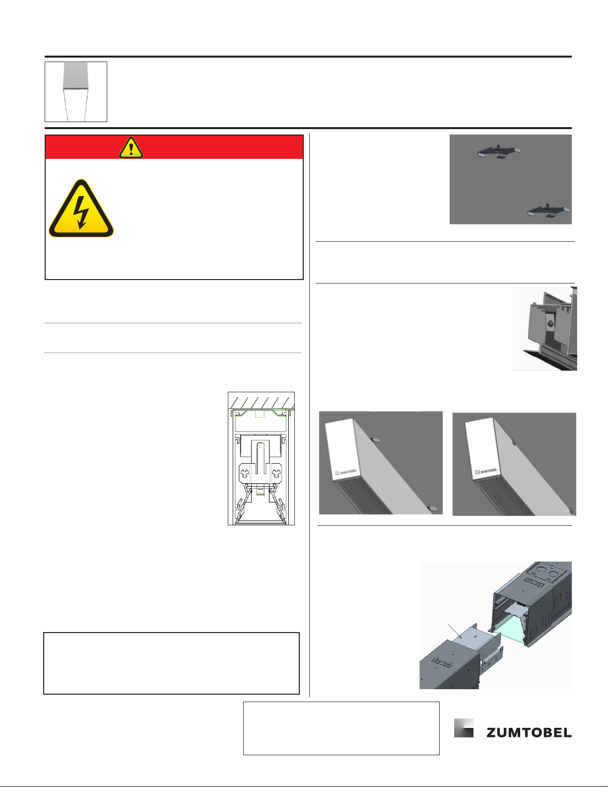
5Install next fixture and connect together by supplied
hardware.
a. Slide fixture over internal joiner.
b. Secure with joining hardware.
c. Make electrical connections
between fixtures
using Quick
connectors at
end of thru
wire harness


