Zweed MOLTO User manual

M O LT O
ASSEMBLY
MANUAL

In this manual we demonstrate a few
examples of Molto combinations and
explain how to assemble the furniture
system. The basic principle is the same
no matter what ends and modules you
have selected so please look through all
the pages as there is some useful advice
in the various examples.
The end frames are reversible and
suitable for both left and right inishes.
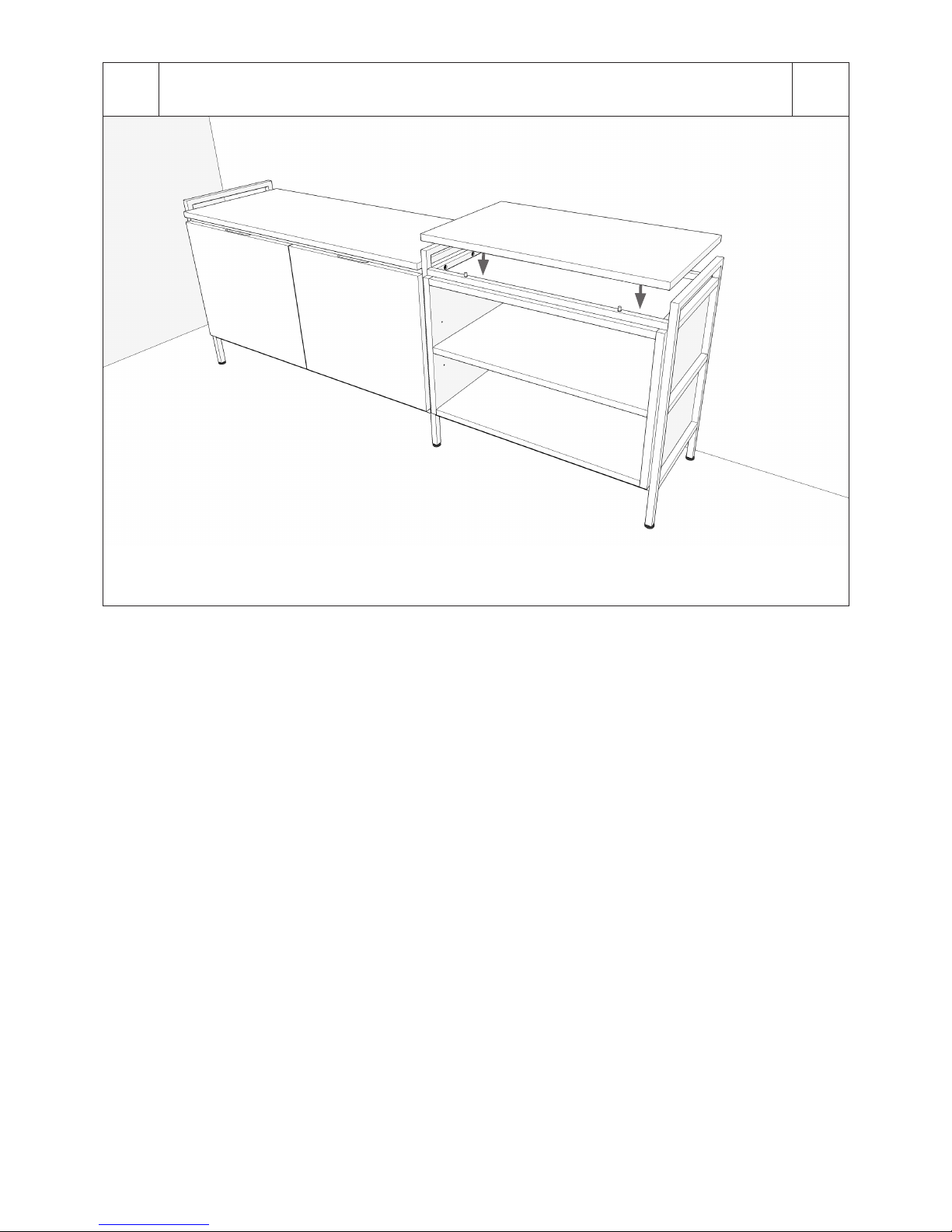
Shelves and modules are delivered
together with the metal frame that is to
be itted underneath.
The following tools are needed in
addition to the ones supplied: spirit
level and hammer. For desk module:
Philip’s screwdriver and 4 mm Allen
key. You will need a drill, screwdriver
and a suitable screw/plug to ix the tip
protection to the wall.
We recommend having one person to
assist when assembling.
A Molto system can be removed and
reinstalled whenever necessary (such
as when moving) and be subsequently
expanded or modiied.
NOTE: For marble shelves, use
supplied rubber pads instead
of guide pins on the frame.
CONTENT
ALOW SYSTEM (FRAME 548) PAGE 3
BMEDIUM SYSTEM (FRAME 935) PAGE 10
CHIGH SYSTEM (FRAME 2100) PAGE 16
DHIGH SYSTEM WITH COAT RACK PAGE 28
BEFORE
YOU START
Zweed Furniture AB
Paviljonggången 8
SE254 51 Helsingborg
Molto furniture system
is designed and
produced by Zweed.
Phone: +46 (0)40 608 02 00
E-mail: hello@zweed.se
www.zweed.se

Our example consists of 2 pcs of end frame 548, 1 pc of center frame 548, 1 pc of cabinet module 840, 1 pc of plain shelf 840,
1 pc of open module 560 and 1 pc of plain shelf 560. 2 pcs of horizontal frame 840 and 2 pcs of horizontal frame 560 are supp-
lied with the modules/shelves.
Start with one of the end sections. If you have diferent widths, select the 840 section. Place one of the wide metal frames on a
soft surface with the hole side facing upwards. Knock the four guide pins down into the holes. Use the hammer where necessary.
NOTE: The pins are packed together with the module/shelf.
A3
A1 X 4
LOW SYSTEM

You always assemble the furniture from the bottom up. Attach the lowest metal frame to the end using three Allen screws.
The Allen key is enclosed with the end packaging. Avoid tightening too hard as this could cause the thread in the end to loosen.
The ends are reversible and can be used for both left and right conigurations.
It is now time to it the right end. This is a center frame with threaded holes on both sides as the furniture is to be built out
to the right.
A3
A2 X 3
X 3
4

Important! Place the steel frame where the furniture is to stand and use a spirit level and the adjustable feet to ensure it is level.
Measure the four diferent positions as shown in the igure. Make sure the feet are unscrewed a few turns from the beginning to
allow you to adjust up or down. This stage is vital for ensuring the modules it well. You can choose to do this later, but it is
signiicantly easier when the frame is not carrying any weight. Tip: Move the steel frame away from the wall a little once you
have adjusted to ensure a better location when itting the modules.
Now put the module in place. One way of reducing the risk for scrapes on the sides of the modules is to loosen the six screws
to the lower frame a few turns. Keep the ends a little apart as demonstrated by the small arrows in the igure. Tighten the screws
from the underneath as soon as the module is in place. Lift the module into the steel frame and align the holes on the underside
in relation to the guide pins in the frame.
A5
A4 5
X 2

Fit the frame that accompanies the shelf on top of the module. Insert the guide pins (as shown in Fig A1) and screw the six Allen
screws in place.
A7
A6 6
X 6
X 4
This section is concluded by putting the shelf in place. Make sure the guide pins match the holes on the underside of the shelf.

Place the inished section in the intended spot. Fit the guide pin in the next frame and then it this to the inished section.
Now it the next end frame.
A9
A8 7
X 6
X 4
Use a spirit level to check that the right section is level and use the adjustable feet if necessary.

Loosen the screws holding the right end frame a few turns, and hold it a little to the side when assembling the open
module in order to avoid scrape marks. Now tighten the screws again once the module is in place. Insert the inner shelf.
A11
A10 8
Fit the upper metal frame.
X 2
X 6
X 4

Finish by installing the upper shelf. Make sure the guide pins match the holes on the underside of the shelf.
A12 9

Our example consists of 2 pcs of end frame 935, 1 pc of center frame 935, 1 pc of drawer module 840, 1 pc of display
module 840, 2 pcs of tray shelf 840 and 2 pcs of plain shelf 840. 6 pcs of horizontal frame 840 are supplied with the modules/
shelves. Tip protection is included for anchoring the frames to the wall.
Follow steps A1-A4 (pages 35) NOTE: If a module is to be itted on top of another, see steps D3–D6 (Pages 2931)
Place the tray shelf in the intended spot. Make sure the guide pins match the holes on the underside of the shelf.
B10
B1
B2
MEDIUM SYSTEM

Fit the next metal frame. Insert the guide pins and screw the frame to the ends. Tighten the screws until they reach the bottom
and then loosen them again a few turns to facilitate the assembly of the module.
B3 11
B4
X 6
X 4
Put the drawer module in place. Keep the ends a little apart as demonstrated by the small arrows in the igure to avoid scrapes
on the sides of the module. Make sure the guide pins match the holes on the underside of the module. Tighten the screws from
the underneath as soon as the module is in place.
X 2

Fit the frame that accompanies the shelf on top of the module. Insert the guide pins and screw the six Allen screws in place.
B5 12
B6
X 6
X 4
Finish by installing the upper shelf. Make sure the guide pins match the holes on the underside of the shelf.

Fit the tray shelf in place and then it the next frame. Release the screws to the right frame a little.
B7
B8
13
B9
Put the display module in place. Make sure the guide pins match the holes on the underside of the module. Keep the right end
frame a little apart as demonstrated by the small arrow in the igure to avoid scrapes on the sides of the module. Tighten the
screws from the underneath as soon as the module is in place.
Follow steps A8–A9 (page 7).
X 6
X 4
X 2

Put the inner shelf in the module. Screw on the accompanying handles to the glass doors. Fit the doors with the irst door instal-
led in the inner groove. Move the door up to the upper inner groove and then push it into the lower one as shown in the igure.
Do the same thing with the other door which is to sit in the outer groove.
B10 14
B11
Fit the frame that accompanies the shelf on top of the module. Insert the guide pins (as shown in Fig A1) and screw the six Allen
screws in place.
1
2
X 6
X 4

Finish by installing the upper shelf. Make sure the guide pins match the holes on the underside of the shelf.
B12 15
B13
Important! For medium and high systems, you must anchor the furniture to the wall in order to avoid accidents. Tip protection
is included with the end frames. In this case, you can it a wall bracket to the center frame below the modules. Make sure you
select a screw/plug (not included) that is designed to suit the wall material and that it is properly secured after assembly.

This high system consists 2 pcs of end frame 2100, 2 pcs of desk center frame 2100, 1 pc of drawer module 560, 1 pc of cabinet
module 840, 1 pc of desk module, 1 pc of tray shelf 560, 1 pc of tray shelf 840, 4 pcs of plain shelf 560 and 7 pcs of plain shelf 840.
2 pcs of special horizontal frames for the desk section, 9 pcs of horizontal frame 840 och 6 pcs of horizontal frame 560 are
supplied with the modules/shelves. Tip protection is included for anchoring the frames to the wall. NOTE! If several modules will
be placed on top of each other, follow step D3–D6 (page 2931).
C
C1
16
HIGH SYSTEM
X 4 4 MM
If the system includes a desk section, start with this. When it comes to the high frames, it is easiest to start assembling these in a
horizontal position. Screw the lower horizontal frame to the underside of the vertical frames as shown in the igure. You will need a
4 mm Allen key (not included). The frames, in this case the center frames, are reversible allowing you to check that they have been
installed as shown in the igure.

Fit the desk module frame. Then lift up the section.
C2 17
C3
C4
Put two pcs of guide pins into the holes as shown in the picture.
X 6
X 2
Assemble the desk module as shown in the accompanying instructions.

C5 18
C6
Important! As the desk generates a lever efect, the entire shelf could tip if, for example, a child climbs onto the desk.
The furniture must be anchored to the wall to avoid accidents. The frame for the desk module has two wall brackets (see the
arrows). Mark the wall with a pen to show where the shelf is to be placed. Move the shelf temporarily to the side, drill a hole
in the wall and it a suitable plug/expander (not included) before reitting the shelf with screws. This task is signiicantly easier
now before you build the rest of the system.
Place the furniture in the intended spot. Allow space for possible side sections, add at least 100 mm to the width of the sections.
Make sure the feet are unscrewed a few turns from the beginning to allow you to adjust up or down. Then use a spirit level and
the adjustable feet to ensure it is level.

C7 19
C8
Put the desk module in place. Align the holes on the underside in relation to the 2 pcs of guide pins in the frame. Tip: One way
of reducing the risk for scrapes on the sides of the module is to loosen the six screws to the horizontal desk frame a few turns.
Keep the vertical frames a little apart as demonstrated by the small arrows in the igure. Tighten the screws from the underneath
as soon as the module is in place.
X 2
X 18
X 12
Insert the guide pins and it the three frames for the shelfs above the desk.

C9 20
C10
Put the shelves in place. Make sure the guide pins match the holes on the underside of the shelves.
X 6
X 4
Continue with the next section. Insert the guide pins and it the lowest horizontal frame and 1 pc of end frame.
Table of contents
Popular Indoor Furnishing manuals by other brands

Touchstone
Touchstone ENCASE FORTE ELITE 90000 Assembly instructions

Round Hill Furniture
Round Hill Furniture B179K-KING SIZE BED Assembly instruction

Kesseböhmer
Kesseböhmer PRIMERO - Comfort HSK Instructions for assembly and use

WATSON
WATSON D9 Assembly

hygena
hygena 314/5041 Assembly instructions

meubar
meubar ARUBA TV7 Assembly instruction