3DAeroventures Super Chipmunk User manual

www.3daeroventures.com
3DAeroventures
Included in Your Download:
1. STL Files
2. Simplify3D Factory Files (for the recommended materials)
3. Recommended Slicer Settings for differnt materials(Excel and PDF format)
4. Generic Gcode for i3 style printers (for the recommended materials)
5. PDF Build Guide
Please Read A Note from the Designer:
First of all, thank you so much for your interest and support of 3DAeroventures. I can’t tell you how
much joy I get out of designing and testing these aircraft, and the fact that you can now get joy out of
my creations just makes this calling that much more special. I dove into the R/C aircraft hobby as a 12
year old kid with my dad and it’s a passion I’ve maintained into adulthood. Part of 3DAeroventures
mission is to encourage people to not let go of the thing they were most passionate about growing up.
That’s why our motto is “Never Stop Exploring. Never Stop Questioning. Never Stop Playing.” I hope
the building and flying of this model keeps your passion for model aviation ignited. More importantly,
I encourage you to share your build and flying process with young people, hopefully igniting a fire in
them and helping to maintain and grow this wonderful hobby.
Now, on to the technical stuff. I haven't been very happy with single wall 3D printed aircraft, and after
playing with so many different materials I am now a big proponent of using multiple material types to
build a good performing and long-lasting craft. So I've totally changed my design methodology for these
planes to meet a few goals: Better printability/surface quality, Increased part strength, the ability to
print the parts in any material - PLA, ABS, ASA, PETG, and especially LW-PLA or LW-ASA, much simpler
slicing and the ability to use any slicer (like Prusa Slicer), and lower my design time so I can release more
designs each year.
I’ve accomplished those goals with the design of this Super Chipmunk. The outer walls of the parts now
print like a corrugated plastic - two single perimeter walls filled with a very low infill, anywhere between
3 - 7%. The downside is, printing this style of design in standard PLA leads to a heavy aircraft, though not
too heavy to fly well. That’s why I am particularly excited about the results I've gotten printing this
aircraft as a hybrid with LW-PLA. My first prototype is printed in PLA and the fully-loaded flying weight,
painted, came in over 4600 grams. It flies great with my recommended Leopard motor on a 6S. But contrast
that to my final prototype, printed as a hybrid LW-PLA version, which came out to 3300 grams, painted. I
highly recommend printing this design in a lighter plastic like ABS/ASA or a combination of LW-PLA and PLA.
I’d love to hear about your build and flight experience with this aircraft. You may contact me directly at
eric@3daeroventures.com with any feedback or troubleshooting questions. Or post your experiences on
the 3DAeroventures Pilots Alliance Facebook Group.
Thanks again and enjoy your flight!
Eric Haddad
Pilot in Command
https://www.facebook.com/groups/3daeroventurespilots
mailto: eric@3daeroventures.com

www.3daeroventures.com
3DAeroventures
Specs:
Scale:
Wingspan:
Length:
Height:
Wing Area:
Wing Loading (LW-PLA Hybrid):
Wing Cube Loading (LW-PLA Hybrid):
Wing Loading (PLA):
Wing Cube Loading (PLA):
Flight Performance Category:
Center of Gravity Location:
1/6 Scale
1625mm / 64”
1356mm / 53.4”
482mm / 19”
704 in²
23.4 oz/ft²
10.6
30.7 oz/ft²
13.9
Scale Aerobatics
75 -
85mm behind the Wing’s Leading Edge
Weight of Printed Parts (LW-PLA Hybrid): 1938g / 68.4 oz
Weight of Printed Parts (PLA):
Flying Weight :
Recommended Max Flying Weight:
No. of Channels:
2817g / 99.4 oz
3250g (LW-PLA) to 4250g (PLA) / 114.6 - 149.9 oz
4500g / 158.7 oz
4 - Throttle, Aileron, Elevator, Rudder
CG Location 75 - 85mm behind
the Wing’s Leading Edge
75 - 85mm

www.3daeroventures.com
3DAeroventures
Tools and Materials Needed:
- Min 200mm x 200mm x 200mm desktop 3D Printer
- ColorFabb LW-PLA or LW-ASA (Recommended)
- High Quality Standard PLA, ABS, ASA, or PETG
- TPU or TPE for Tires
- Medium Bodied CA/Super Glue
- Accelerator for CA
- Two-Part Epoxy Adhesive - 5-minute cure time
- Sandpaper and/or Small Files
- Spray Paint or Airbrush Paints
- Velcro strips with adhesive backing
- Screwdriver and/or allen wrench for chosen screws/bolts
- Needle Nose Pliers
- Dremel/Rotary Tool for cutting carbon fiber tubes
Recommended Setup:
Motor Options:
ESC Options:
Rec. Prop Size:
Battery:
Radio:
Servos:
Leopard 5065-7T - 380kV
Leopard 5055-10T - 390kV
Turnigy Aerodrive SK3 5055-430kV
or motor with equivalent mounting pattern
80A Esc like Hobbywing Skywalker Series 80A ESC
15x8 to 16x10 (follow your motor’s recommendations within this range)
6S 5000 mAh LiPo (PLA, ABS/ASA, or PETG version)
5S 5000mAh LiPo (LW-PLA Hybrid version)
Radio + 4ch - 6ch Reciever
EMAX ES3004 or EMAX ES3054 or equivelant size servo (x4)
EMAX ES-3005 or Flite Test ES3005 or equivalent size servo (x1)
Y Harness for aileron and elevator servos (optional)
- We recommend using a 6 channel receiver to mix servos
instead of using a Y Harness

www.3daeroventures.com
3DAeroventures
Hardware Needed:
- M3 x 0.5mm Thread x 12mm Long Screws for Cowling and Landing Gear.................................
- M3 x 0.5mm Thread x 25mm Long Screws for Spinner.............................................................
- M4 x 0.7mm Thread x 16mm Long Screws for Motor Mount and Wing Mount...........................
- M5 x 0.8mm Thread x 40mm Long Screws for Landing Gear.....................................................
- M3 x 0.5mm Thread Lock Nut for Spinner................................................................................
-
- M4 x 0.7mm Thread Lock Nut for Motor Mount........................................................................
- M4 x 0.7mm Thread Heat-Set Threaded Inserts for Wing Mounts............................................
- M5 x 0.8mm Thread Lock Nut for Landing Gear........................................................................
- Steel washer for M5 Screw Size for Landing Gear.....................................................................
- M2 or #2 Thread Forming or Tapping Screws for mounting servo covers.................................
- 3mm O.D. (or 1/8” O.D) x 10mm Long Dowel Pins (cut from scrap carbon tube/rod)..................
-6mm O.D. Carbon Fiber Tubes
- 600mm (or 24“) Long for Wings (x6).............................................................................
- 500mm Long for Horizontal Stab.................................................................................
- 220mm Long for Vertical Stab......................................................................................
-1mm - 1.5mm O.D. Carbon fiber rod or Steel Wire
- 650mm Long for Aileron Hinges (x2)............................................................................
- 550mm Long for Elevator Hinge...................................................................................
- 220mm Long for Rudder Hinge.....................................................................................
-2mm (or 2-56) diameter steel wire with threaded ends for servo control rods
-
-
- 1.8mm - 2mm diameter steel wire for tailwheel wire................................................................
- Nylon or Steel Kwik-Links........................................................................................................
- Adjustable Pushrod Connectors (optional)..............................................................................
- Wheel Collars to fit 5mm rod (main landing gear)....................................................................
- Wheel Collar to fit 2mm rod (tailwheel)...................................................................................
- 4” servo extensions for aileron servos....................................................................................
- 6” servo extensions for aileron ports in receiver.....................................................................
Quantity:
12
2
12
2
2
M3 x 0.5mm Thread Heat-Set Threaded Insertsfor Cowling and Landing Gear......................... 12
8
4
2
2
8
9
2
1
2
2
1
1
30” for elevator and rudder.......................................................................................... 3
12” for ailerons............................................................................................................. 2
1
5
3
2
1
2
2
- 4mm O.D. x 20 - 25mm Long Compression Spring for Canopy Latch........................................1
- Note: The spring from a click pen or mechanical pencil will work

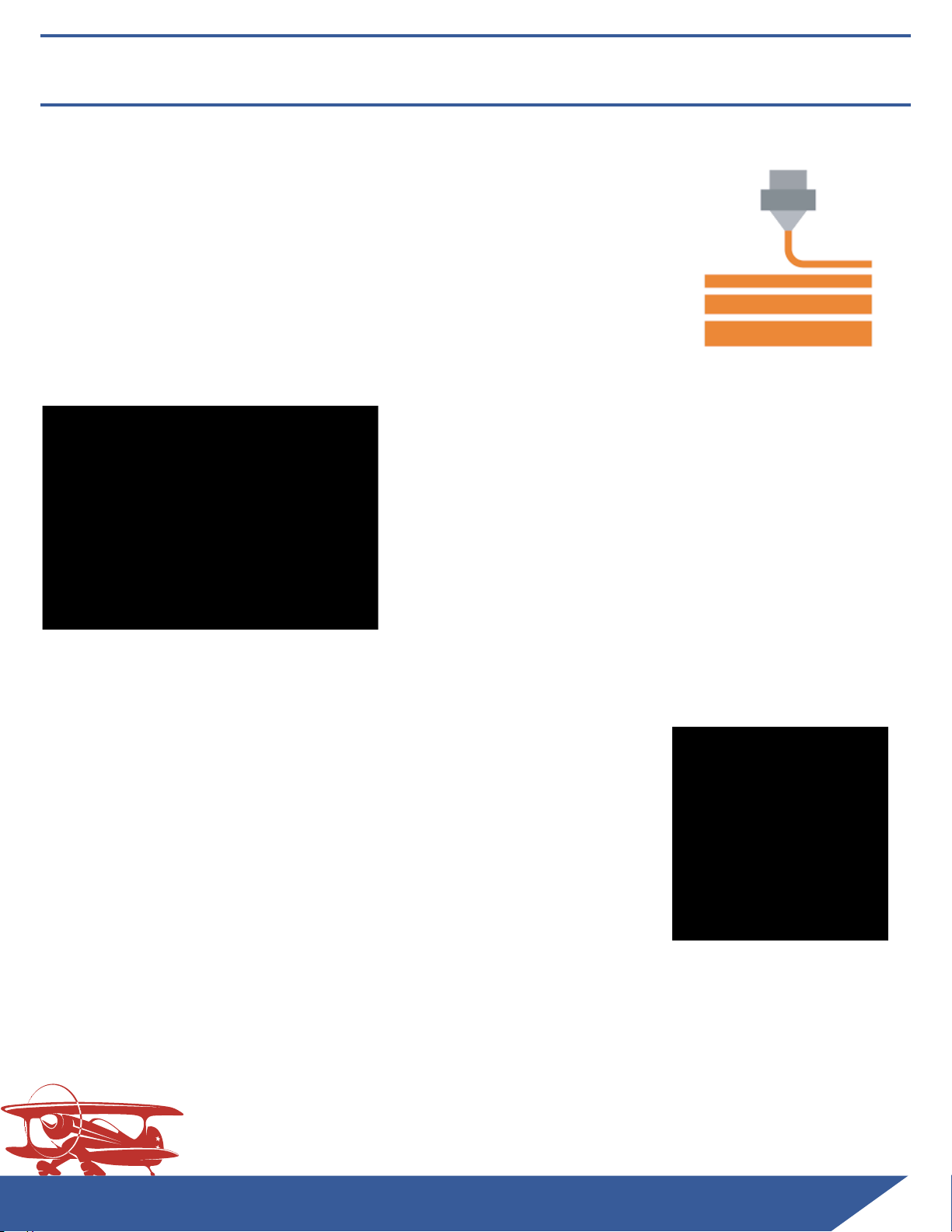
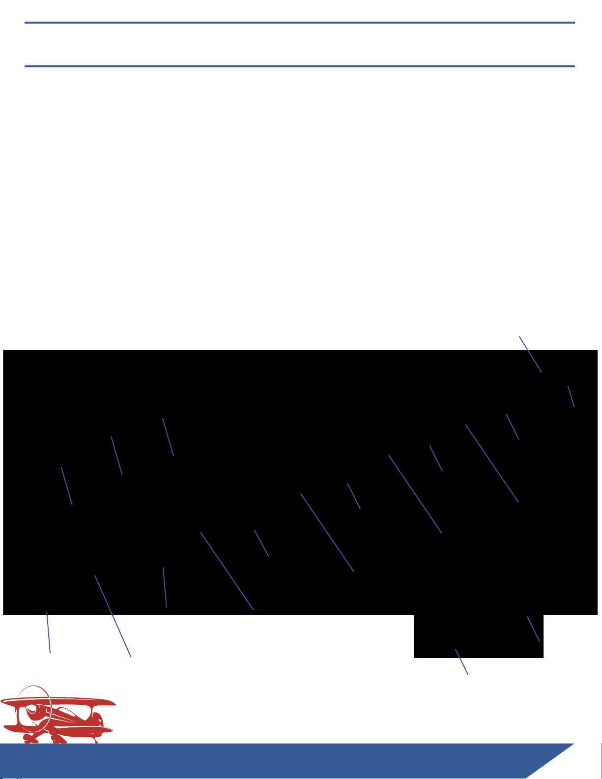
Estimated Part Weights by Material Type (Grams):
Hardware Needed:
- 5mm O.D x 3mm Thick Rare Earth Magnets for Removable Canopy.........................................
- M3 x 0.5mm Thread x 12mm Long Screws for Cowling and Landing Gear.................................
- M3 x 0.5mm Thread x 25mm Long Screws for Spinner.............................................................
- M4 x 0.7mm Thread x 16mm Long Screws for Motor Mount and Wing Mount...........................
- M5 x 0.8mm Thread x 40mm Long Screws for Landing Gear.....................................................
- M3 x 0.5mm Thread Lock Nut for Spinner................................................................................
- M3 x 0.5mm Thread Heat-Set Threaded Inserts for Cowling and Landing Gear.........................
- M4 x 0.7mm Thread Lock Nut for Motor Mount........................................................................
- M4 x 0.7mm Thread Heat-Set Threaded Inserts for Wing Mounts............................................
- M5 x 0.8mm Thread Lock Nut for Landing Gear........................................................................
- Steel washer for M5 Screw Size for Landing Gear.....................................................................
- M2 or #2 Thread Forming or Tapping Screws for mounting servo covers.................................
- 3mm O.D. (or 1/8” O.D) x 10mm Long Dowel Pins (cut from scrap carbon tube/rod)..................
- 6mm O.D. Carbon Fiber Tubes
- 600mm (or 24“) Long for Wings (x6).............................................................................
- 500mm Long for Horizontal Stab.................................................................................
- 220mm Long for Vertical Stab......................................................................................
- 1mm - 1.5mm O.D. Carbon fiber rod or Steel Wire
- 650mm Long for Aileron Hinges (x2)............................................................................
- 550mm Long for Elevator Hinge...................................................................................
- 220mm Long for Rudder Hinge.....................................................................................
- 2mm (or 2-56) diameter steel wire with threaded ends for servo control rods
- 30” for elevator and rudder..........................................................................................
- 12” for ailerons.............................................................................................................
- 1.8mm - 2mm diameter steel wire for tailwheel wire................................................................
- Nylon or Steel Kwik-Links........................................................................................................
- Adjustable Pushrod Connectors (optional)..............................................................................
- Wheel Collars to fit 5mm rod (main landing gear)....................................................................
- Wheel Collar to fit 2mm rod (tailwheel)...................................................................................
- 4” servo extensions for aileron servos....................................................................................
- 6” servo extensions for aileron ports in receiver.....................................................................
Part Name
Hybrid
PLA/LW-PLA Recommended Material
for Hybrid
Estimated
PLA/PETG
Weights
Estimated
ABS/ASA
Weights
Fuse 1 78 LW-PLA
149
126
Fuse 2
1
37
PLA
137
149
Fuse 3
134
PLA
134
112
Fuse 4 43 LW-PLA 81 71
Fuse 5 40 LW-PLA 74 65
Fuse 6 38 LW-PLA 71 62
Fuse 7 28 LW-PLA 59 52
Fuse Tray 1 20 PLA 20 18
Fuse Tray 2 28 PLA 2825
Fuse Tray 3 18 PLA 1816
Fuse Tray 4 16 PLA 16 14
Fuse Tray 5 10 PLA 10 9
Wing R1
100
PLA
100 88
Wing R2 56 LW-PLA 103 91
Wing R3 48 LW-PLA 86 76
Wing R4 43 LW-PLA 81 71
Wing R5 35 LW-PLA 65 57
Wing L1
100
PLA
100 88
Wing L2 56 LW-PLA 103 91
Wing L3 48 LW-PLA 86 76
Wing L4 43 LW-PLA 81 71
Wing L5 35 LW-PLA 65 57
Wing Trailing Edge R 13 LW-PLA 23 20
Wing Trailing Edge L 13 LW-PLA 23 20
Wing Tip R 8 LW-PLA 16 14
Wing Tip L 8 LW-PLA 16 14
Wing Servo Covers 15 PLA 15 15
Aileron R1 14 LW-PLA 24 21
Aileron R2 14 LW-PLA 24 21
Aileron R3 14 LW-PLA 24 21
Aileron R4 14 LW-PLA 24 21
Aileron L1 14 LW-PLA 24 21
Aileron L2 14 LW-PLA 24 21
Aileron L3 14 LW-PLA 24 21
Aileron L4 14 LW-PLA 24 21
Canopy 1 12 LW-PLA 25 22
Canopy 2 30 LW-PLA 56 49
Canopy 3 32 LW-PLA 60 53
Cowl 1 14 LW-PLA 32 38
Cowl 2 90PLA 9090
Elev R1 8 LW-PLA 17 15
Elev R2 8 LW-PLA 13 11
Elev R3 6 LW-PLA 11 10
Elev R4 6 LW-PLA 14 12
Elev L1 8 LW-PLA 17 15
Elev L2 8 LW-PLA 13 11
Elev L3 6 LW-PLA 11 10
Elev L4 6 LW-PLA 14 12
HorizStab R1 14 LW-PLA 27 24
HorizStab R2 13 LW-PLA 22 19
HorizStab R3
10
LW-PLA 1917
HorizStab L1 14 LW-PLA 27 24
HorizStab L2 13 LW-PLA 22 19
HorizStab L3 10 LW-PLA 1917
Landing Gear R1
41
PLA
41
36
Landing Gear R2
43
PLA
43
40
Landing Gear L1
41
PLA
41
36
Landing Gear L2
43
PLA
43
40
Motor Mount
65
ABS, ASA, or PETG 65 (PETG) 57
Rudder 1 6 LW-PLA 13 11
Rudder 2 12 LW-PLA 22 19
Rudder 3 11 LW-PLA 1917
Rudder 4 13 LW-PLA 22 19
Vert Stab 1 10 LW-PLA 17 15
Vert Stab 2 11 LW-PLA 1917
Control Horns 11 PLA, ABS, ASA, or PETG 11 11
Printed Part Weight
1938 2817 2507
OPTIONAL
PARTS
Estimated
Weights Recommended Material
Tire 20 TPU/TPE
Tire Hub 1 7 PLA, ABS, ASA, or PETG
Tire Hub 2 7 PLA, ABS, ASA, or PETG
Tailwheel Tire 2 TPU/TPE
Tailwheel Hub 1 1 PLA, ABS, ASA, or PETG
Tailwheel Hub 2 1 PLA, ABS, ASA, or PETG
Spinner 1 25 PLA, ABS, ASA, or PETG
Spinner 2 9 PLA, ABS, ASA, or PETG
Weights

www.3daeroventures.com
3DAeroventures
Step-by-Step Build Guide
Step 1. 3D Printing the Included Parts
Minimum Requirements:
200mm x 200mm x 200mm Print Bed Size
0.4mm Nozzle
Heated Bed (recommended)
Any Slicer Software
Option 1: G-Code
Transfer the included G-Code to an SD Card and run directly
on your i3 style printer using the materials we recommend. The
provided G-Code is for our recommended PLA / LW-PLA Hybrid build.
We’ve had good results with LW-PLA at 250º Celcius and standard
PLA at 225º Celcius but experiment with your printer to make sure
you achieve strong layer adhesion. If you wish to print this aircraft
from a different material, reference the included Slicer Settings PDF
and use your preferred slicer.
Option 2: Simplify 3D Factory Files
If you prefer to use Simplify3D as your slicer, open
the included Factory Files and edit the preset profiles
for your printer/material to ensure nice outer surfaces
and excellent layer bonding.
Your Options for Printing the Parts:
Option 3: STL + Your Preferred Slicer
If you prefer to use another slicer or create your own profiles
in Simplify3D, use the included STL files and reference the
included Recommended Slicer Settings PDF.

www.3daeroventures.com
3DAeroventures
Step-by-Step Build Guide (cont’d)
3D Printing Tips
Standard PLA Temperatures:
We see good results printing Paramount3D PLA at 225ºC
with a bed temperature of 70ºC. Experiment with your
particular printer and brand of material to ensure proper
layer bonding but you will likely land somewhere between
210 and 240ºC.
Cooling Fan:
Typically, PLA is printed with the fan set to 100%. However,
this can cause layer bonding issues when printing thin walled
aircraft. We have experienced nice , clean outer surfaces
when keeping the fan speed up to 20% without negatively
affecting layer bonding. Experiment with fan speeds set
between 0 - 20%.
ColorFabb LW-PLA
ColorFabb LW-PLA is an interesting material that uses foaming
technology to achieve lightweight, low density PLA parts. This
material is printed at a higher temperature (which causes it
to expand) and a much lower extrusion multiplier than standard
PLA. In order to determine the proper nozzle temperature and
extrusion multipler for your particular printer you can follow
ColorFabb’s instructions: https://learn.colorfabb.com/print-lw-pla/
We had good results printing LW-PLA at 250ºC at an Extrusion Multiplier of 0.4
and a bed temp of 60ºC. You will also likely combat quite a bit of stringing with
LW-PLA. We increase X/Y Axis Movement Speed to 200mm/s and run the cooling
fan at 25% to help combat stringing.

www.3daeroventures.com
3DAeroventures
Step-by-Step Build Guide (cont’d)
3D Printing Tips (cont’d)
Standard Materials Extrusion Multiplier (Flow):
You will need to experiment with extrusion multiplier for
your particular printer and material. You will likely land
somewhere between 0.95 and 1.05 extrusion multiplier.
Elephant’s Foot:
Try to avoid the first few layers of each print from
squishing too far outside the designed wall dimensions,
also known as “elephant’s foot”. This can be caused by
your nozzle being too close to the print bed or first layer
width set too high in your slicer. A small amount of
elephant’s foot is okay but too much will interfere with
the designed alignment aids.
Support Structures:
The “Fuse Tray 3” part of this aircraft requires
support structures and it’s recommended to
use your slicer’s auto-generated support
structures. The GCode and the Simplify3D
Factory Files already have the support structures
in place.

Fuse 1
Fuse 4
Fuse Tray 1 (PLA)
Fuse Tray 2 (PLA)
Fuse Tray 3 (PLA)
Fuse Tray 4 (PLA)
Fuse Tray 5 (PLA)
Fuse 2 (PLA)
Fuse 3 (PLA)
Canopy 1
Canopy 2
Canopy 3
Canopy Latch
Canopy Latch Cover
Fuse 5
Fuse 6
Fuse 7
Tailwheel Wire
(bending instructions on pg. 12)
www.3daeroventures.com
3DAeroventures
Step 2. Fuselage Assembly
Tools and Materials Needed:
- Medium Bodied CA/Super Glue
- Accelerator for CA
- Two-Part Epoxy Adhesive - 5-minute cure time
- Sandpaper and/or Small Files
- Hobby Knife
- Needle Nose Pliers for bending tailwheel wire
Step-by-Step Build Guide (cont’d)
Printed Parts Needed:
Hardware Needed (links to recommended hardware on pg 5):
- 4mm O.D. x 20 - 25mm Long Compression Spring (from a click pen or mechanical pencil)
- 3mm O.D. (or 1/8” O.D) x 10mm Long Dowel Pins (cut from scrap carbon tube/rod) (x3)
- M3 x 0.5mm Thread Heat-Set Threaded Inserts for Cowling (x4)
- M4 x 0.7mm Thread Heat-Set Threaded Inserts for Wing Mounts
- M4 x 0.7mm Thread Lock Nut for Motor Mount
(x4)
-
1.8mm - 2mm diameter steel wire for tailwheel wire

www.3daeroventures.com
3DAeroventures
Step-by-Step Build Guide (cont’d)
Step 2.1 Bend the Tailwheel Wire to Shape
ATTENTION: Do not glue Fuse 7 into place without the tailwheel wire set in place
between Fuse 6 and Fuse 7. Print out the drawing of the tailwheel wire on the
following page to aid in bending a 1.8mm - 2mm diameter steel wire to the proper
shape. Set aside for a later step.

Step 2.2 Glue Motor Mount Locknuts in Place
2.3.1 Once the epoxy has dried, use a soldering iron to sink qty. 4, M3 x 0.5mm
Thread Heat-Set Inserts in place in the cowl mounting holes, which are
located on the sides of Fuse 1.
Step 2.3 Heat Set Inserts for Cowling and Wing Mounts
www.3daeroventures.com
3DAeroventures
Step-by-Step Build Guide (cont’d)
Use the two-part epoxy resin to permanently glue the qty. 4, M4 x 0.7mm Thread
Lock Nuts in place in the hex-shaped recesses behind the firewall of Fuse 1.
Permanently Glue
M4 Locknuts Here
Place M3 Heat-Set
Inserts Here

When printing with LW-PLA you will likely have some residual stringing. Inspect
all of the printed parts for stringing and use sand paper, a small file or a hobby
knife to eliminate the stringing, especially in areas where parts will mate. You
will find most of the stringing comes off quite easily.
Step 2.4 Cut or Sand Away Any Stringing
2.3.2 Use the soldering iron to sink qty. 4, M4 x 0.7mm Thread Heat Set Inserts
in place in the wing mounting holes, which are located on the sides of
Fuse 2 and Fuse 3.
www.3daeroventures.com
3DAeroventures
Step-by-Step Build Guide (cont’d)
Place M4 Heat-Set
Inserts Here
Fuse 2 (PLA)
Fuse 3 (PLA)

www.3daeroventures.com
3DAeroventures
Step-by-Step Build Guide (cont’d)
Step 2.5 Glue Fuselage and Fuse Tray Parts Together
ATTENTION: The fuselage is designed with separate Fuse Tray parts. This was done
in case you choose to print the Fuse parts in LW-PLA or LW-ASA. The Fuse Tray parts
should be printed in a more rigid plastic like standard PLA, ABS, PETG, or PC.
The Fuse parts must be assembled with the Fuse Tray parts in a certain order. You
will notice the Fuse Tray parts slide into rails located in the Fuse parts. The Trays
overlap the seams of the Fuse parts and make for a very strong, rigid fuselage.
DO NOT GLUE ALL OF THE FUSE PARTS TOGETHER
WITHOUT THE FUSE TRAY PARTS IN PLACE!

www.3daeroventures.com
3DAeroventures
Step-by-Step Build Guide (cont’d)
2.5.1 Starting with Fuse 1, apply CA adhesive to the rails where Fuse Tray 1 slides
into place. Ensure Fuse Tray 1 is fully seated into place in the rail behind
the firewall and wipe off any residual glue from the Fuse 1 surface that
mates with Fuse 2 before applying CA Accelerator to secure the bond.
Step 2.5 Glue Fuselage and Fuse Tray Parts Together (cont’d)
The Tray slides into these three rails
Ensure the tray is fully seated into
the rail behind the firewall
before applying accelerator

2.5.2 Glue part Fuse 2 to the Fuse 1 sub-assembly. Make sure to apply the CA glue
to the mating faces of Fuse 1 and Fuse 1 as well as the portions of Fuse Tray 1
that slide into the rails inside Fuse 2.
NOTE: Because of the stringing of LW-PLA you may need to clean up the
alignmet tabs and alignment holes with a hobby knife
2.5.3 Now glue part Fuse Tray 2 into your assembly just as you did with Fuse Tray 1.
Apply the CA glue to the rails inside Fuse 2 and slide Fuse Tray 2 in place until
fully seated before applying accelerator.
www.3daeroventures.com
3DAeroventures
Step-by-Step Build Guide (cont’d)
Make sure to apply CA Glue here as well

2.5.4 Repeat Steps 2.5.2 and 2.5.3 for the remainder of the Fuse and Fuse Tray parts,
followng the order shown in the image below.
Step-by-Step Build Guide (cont’d)
www.3daeroventures.com
3DAeroventures
ATTENTION: Stop after gluing part Fuse 6 in place. Do not glue Fuse 7 into place
without the tailwheel wire set between Fuse 6 and Fuse 7. Print out the drawing
of the tailwheel wire on page 12 to aid in bending a 1.8mm - 2mm diameter steel
wire to the proper shape.
Fuse 4
Fuse Tray 3 (PLA)
Fuse Tray 4 (PLA)
Fuse Tray 5 (PLA)
Fuse 3 (PLA)
Fuse 5
Fuse 6

2.5.5 Rest the bent tailwheel wire in place in Fuse 7 and glue Fuse 7 to Fuse 6, taking
care not to get any adhesive on the tailwheel wire. Once assembled, the
90 degree bend that is at the top of the tailwheel wire should stick out the back
as shown in the figures below. This is the portion of the wire that will engage
with the rudder during final assembly.
Step-by-Step Build Guide (cont’d)
www.3daeroventures.com
3DAeroventures

2.5.6 Using a hot knife or soldering iron, follow the molded in line/guide to cut away
the sacrificial support located on Fuse 2 and Fuse 3.
Step-by-Step Build Guide (cont’d)
www.3daeroventures.com
3DAeroventures
Table of contents
Other 3DAeroventures Toy manuals
Popular Toy manuals by other brands

Kazuma
Kazuma Meerkat 50 owner's manual

Mega Bloks
Mega Bloks Halo Collectors Case quick guide

Rompa
Rompa 19455 quick start guide

VolantexRC
VolantexRC TW-759-1 instructions

VTech Baby
VTech Baby Cuddle & Swing Monkey 5134 Parents' guide

Hasbro
Hasbro Transformers Meteorfire Cyberverse Adventures Battle Call Trooper Class... manual

LEGO
LEGO 4437 City user guide

PARKZONE
PARKZONE Vapor BNF instruction manual

TRANSFORMERS
TRANSFORMERS CYBERVERSE POWER OF THE SPARK SCRAPLET instructions

Fisher-Price
Fisher-Price 78378 instructions

marklin
marklin Langenschwalbacher-Wagen instruction manual

Eduard
Eduard A-26B Invader seatbelts STEEL manual