3DAeroventures X-100 Infinity Wing V2 User manual

www.3daeroventures.com
3DAeroventures
https://www.facebook.com/groups/3daeroventurespilots
mailto: eric@3daeroventures.com
Included in Your Download:
1. STL Files
2. Simplify3D Factory Files (for the recommended materials)
3. Cura and PrusaSlicer Profiles and Recommended Slicer Settings for different materials
4. Generic Gcode for i3 style printers (for the recommended materials)
5. PDF Build Guide
Please Read A Note from the Designer:
First of all, thank you so much for your interest and support of 3DAeroventures. I can’t tell you how
much joy I get out of designing and testing these aircraft, and the fact that you can now get joy out of
my creations just makes this calling that much more special. I dove into the R/C aircraft hobby as a 12
year old kid with my dad and it’s a passion I’ve maintained into adulthood. Part of 3DAeroventures
mission is to encourage people to not let go of the thing they were most passionate about growing up.
That’s why our motto is “Never Stop Exploring. Never Stop Questioning. Never Stop Playing.” I hope
the building and flying of this model keeps your passion for model aviation ignited. More importantly,
I encourage you to share your build and flying process with young people, hopefully igniting a fire in
them and helping to maintain and grow this wonderful hobby.
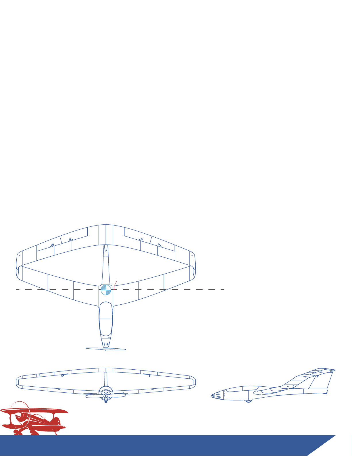
Now, on to the technical stuff. The X-100 Infinity Wing has been re-designed into this V2 version to meet
several goals: Improved stall performance, better printability/surface quality, increased part strength,
the ability to print the parts in any material - PLA, ABS, ASA, PETG, and especially LW-PLA or LW-ASA, and
much simpler slicing and the ability to use any slicer (like Prusa Slicer). I am now a big proponent of using
multiple material types to build a good performing and long-lasting craft. So you should find this style of part
design to be simpler to slice on your own and print in many different materials. The outer walls of the parts
now print like a corrugated plastic - two single perimeter walls filled with a very low infill, anywhere between
3 - 7%. The downside is, printing this style of design in standard PLA leads to a heavier aircraft, though not
too heavy to fly well. That’s why I am particularly excited about the results I've gotten printing this aircraft
as a hybrid with LW-PLA. I recommended at least printing some of the parts in LW-PLA to keep the weight as
low as possible and for the ideal weight distribution. The hybrid version balances perfectly at the new
recommended CG position with a 3S 2200mah battery located in the middle of the battery compartment. A
standard PLA version may require a larger battery or a small amount of nose weight to properly balance. If
you do only print a few of the parts in LW-PLA I recommend printing the Back Wing parts in LW-PLA for better
weight distribution.
I’d love to hear about your build and flight experience with this aircraft. You may contact me directly at
eric@3daeroventures.com with any feedback or troubleshooting questions. Or post your experiences on
the 3DAeroventures Pilots Alliance Facebook Group.
Thanks again and enjoy your flight!
Eric Haddad
Pilot in Command

www.3daeroventures.com
3DAeroventures
Specs:
Wingspan: 1270mm / 50”
Length: 879mm / 34.6”
Height: 242.5mm / 9.5”
Wing Area: 437.5 in²
Wing Loading (LW-PLA Hybrid): 13.3 oz/ft²
Wing Cube Loading (LW-PLA Hybrid): 7.5
Wing Loading (PLA): 17.6 oz/ft²
Wing Cube Loading (PLA): 10.1
Flight Performance Category: General Sport and Scale Aerobatics
Center of Gravity Location: 45mm in Front of Trailing Edge at the Wing Root
Weight of Printed Parts(LW-PLA Hybrid): 684g / 24.1 oz
Weight of Printed Parts(PLA): 1048g / 37 oz
Flying Weight (3S 2200 mAh): 1130g (LW-PLA) to 1520g (PLA) / 39.9 - 53.6 oz
Recommended Max Flying Weight: 1800g / 63.5 oz
No. of Channels: 3 - Throttle, Aileron, Elevator (Elevons)
CG Location 45mm in front
of the Trailing Edge of the
Wing Root
45mm

www.3daeroventures.com
3DAeroventures
Tools and Materials Needed:
- Min 200mm x 200mm x 205mm desktop 3D Printer
- 3D Printing Material of Choice (LW-PLA and PLA hybrid recommended)
- PETG, ABS, ASA, or PC for motor mount
- TPU or TPE for Belly Wheel Tire
- Medium Bodied CA/Super Glue
- Accelerator for CA
- Sandpaper and/or Small Files
- Soldering Iron (for heat set threaded inserts)
- Screwdriver and/or allen wrench for chosen screws/bolts
https://www.altitudehobbies.com/collections/35mm-series/products/leopard-3536-8t-960kv-brushless-airplane-motor
https://www.altitudehobbies.com/collections/skywalker-series/products/hobbywing-skywalker-series-40a-esc?variant=13581840777275
https://www.altitudehobbies.com/products/emax-es08ma-ii-8g-analog-metal-gear-servo?variant=13581874167867
https://www.altitudehobbies.com/collections/35mm-series/products/leopard-3542-7t-780kv-brushless-airplane-motor
https://amzn.to/2QhIKr7
https://amzn.to/2Qhzxip
https://amzn.to/3cWUeda
https://amzn.to/2w6wOS6
https://amzn.to/2QeqXB6
https://amzn.to/3aSs55d
https://amzn.to/2QhsAhc
https://dragonplate.com/DragonPlate-Carbon-Tube-6mm-OD-x-150ID-x-24
https://www.mcmaster.com/90576a102
https://www.mcmaster.com/94180a333
https://www.paramount-3d.com/
https://www.mcmaster.com/90380a011
https://www.mcmaster.com/91290a572
Recommended Setup:
Motor Options: EFlite Power 15
Leopard 3536-7T 1100kV
or motor with equivalent X mounting pattern
ESC Options: 40A or 50A Esc like HobbyWing Skywalker Series 40A ESC
Rec. Prop: 12x8(EFlite) or 11x6 (Leopard) Folding Propeller
Battery: 3S 2200mAh LiPo or
4S 2200 - 3300 mAh
Radio: Radio with Elevon Mixing Capability + 4 Channel Reciever
Servos: EMAX ES08MA II (12g) Metal Gear Servo or equivalent 23x11.5x24mm size servo (x2)
24” Servo Extensions (x2)
6” Servo Extensions (x2)
Hardware Needed:
Fuselage:
-M3 x 0.5mm Thread Heat-set Threaded Inserts for wing bolts
-M3 x 0.5mm Thread Lock Nuts for motor mount
-M3 x 0.5mm Thread x 15mm (or 30mm) Long Socket Head Screws for motor mount
- 5mm O.D x 3mm Thick Rare Earth Magnets for Removable Canopy
- 3mm O.D. Carbon Fiber rod or equivelent O.D. wood or plastic dowel for wheel axles
- M2 or #2 Thread Forming or Tapping Screws for mounting cowl
(spare servo mounting screws will work)
Wings:
-M3 x 0.5mm Thread Heat-set Threaded Inserts for wing tip bolts
-M3 x 0.5mm Thread x 10mm Long Socket Head Screws for removable wings
-M2 or #2 Thread Forming or Tapping Screws for mounting servo covers
- 6mm O.D. x 4mm I.D. (or 0.150” I.D.) x 600mm Long Carbon Fiber Hollow Tubes
for wing spars cut to these lengths:
- 300mm Long (x3)
- 200mm Long (x1)
- 1mm - 1.5mm O.D. x 400mm Long Carbon fiber rod or Steel Wire for Elevon Hinges
- 1.2 mm steel wire for servo control rods
Quantity:
8
4
4
4
2
4
4
12
8
3x 300mm long
1x 200mm long
2
https://www.apcprop.com/product/fh45mm-6/
https://www.apcprop.com/product/12x8-5f/
https://amzn.to/2QeqXB6
https://amzn.to/3cVQx7v

www.3daeroventures.com
3DAeroventures
Estimated Part Weights by Material Type (Grams):
Part Name
Hybrid
PLA/LW-
PLA
Recommended Material
for Hybrid
Estimated
PLA/PETG
Weights
Fuse 1 38 LW-PLA 65
Fuse 2 50LW-PLA82
Fuse 3 20LW-PLA31
Fuse 4 12 LW-PLA21
Fuse Tray 1 12 PLA12
Fuse Tray 2 8 PLA8
Fuse Tray 3 4 PLA4
Canopy 1 11 LW-PLA20
Canopy 2 10LW-PLA17
Vert Stab 18 LW-PLA26
Back Wing R1 13 LW-PLA20
Back Wing R2 25 LW-PLA38
Back Wing R3 15 LW-PLA26
Back Wing R4 14 LW-PLA22
Back Wing R5 15 LW-PLA23
Back Wing L1 13 LW-PLA20
Back Wing L2 25 LW-PLA38
Back Wing L3 15 LW-PLA26
Back Wing L4 14 LW-PLA22
Back Wing L5 15 LW-PLA23
Front Wing R1 40LW-PLA 60
Front Wing R2 31 LW-PLA47
Front Wing R3 27LW-PLA40
Front Wing L1 40LW-PLA 60
Front Wing L2 31 LW-PLA47
Front Wing L3 27LW-PLA40
Back Wing Tip R8 LW-PLA18
Back Wing Tip L 8 LW-PLA18
Front Wing Tip R8 LW-PLA18
Front Wing Tip L 8 LW-PLA18
Middle Wing Tip R3 LW-PLA 6
Middle Wing Tip L 3 LW-PLA 6
Elevon R1 16LW-PLA27
Elevon R2 12 LW-PLA21
Elevon L1 16LW-PLA27
Elevon L2 12 LW-PLA21
Cowl 12 PLA12
Servo Cover R 6 PLA 6
Servo Cover L 6PLA 6
Motor Mounts 9PETG
Tire 7TPU/TPE
Tire Hub 1 3
PLA3
Tire Hub 2 3
PLA3
Tailwheel 1 TPU/TPE
Printed Part Weight 684 1048

www.3daeroventures.com
3DAeroventures
Step-by-Step Build Guide
Step 1. 3D Printing the Included Parts
Minimum Requirements:
200mm x 200mm x 200mm Print Bed Size
0.4mm Nozzle
Heated Bed (recommended)
Any Slicer Software
Option 1: G-Code
Transfer the included G-Code to an SD Card and run directly
on your i3 style printer using the materials we recommend. The
provided G-Code is for our recommended PLA / LW-PLA Hybrid build.
We’ve had good results with LW-PLA at 250º Celcius and standard
PLA at 225º Celcius but experiment with your printer to make sure
you achieve strong layer adhesion. If you wish to print this aircraft
from a different material, reference the included Slicer Settings PDF
and use your preferred slicer.
Option 2: Simplify 3D Factory Files
If you prefer to use Simplify3D as your slicer, open
the included Factory Files and edit the preset profiles
for your printer/material to ensure nice outer surfaces
and excellent layer bonding.
Your Options for Printing the Parts:
Option 3: STL + Your Preferred Slicer
If you prefer to use another slicer or create your own profiles
in Simplify3D, use the included STL files and reference the
included Recommended Slicer Settings PDF. Cura and PrusaSlicer
profiles for PLA are also provided

www.3daeroventures.com
3DAeroventures
Step-by-Step Build Guide (cont’d)
3D Printing Tips
Standard PLA Temperatures:
We see good results printing Paramount3D PLA at 225ºC
with a bed temperature of 70ºC. Experiment with your
particular printer and brand of material to ensure proper
layer bonding but you will likely land somewhere between
210 and 240ºC.
Cooling Fan:
Typically, PLA is printed with the fan set to 100%. However,
this can cause layer bonding issues when printing thin walled
aircraft. We have experienced nice , clean outer surfaces
when keeping the fan speed up to 20% without negatively
affecting layer bonding. Experiment with fan speeds set
between 0 - 20%.
ColorFabb LW-PLA
ColorFabb LW-PLA is an interesting material that uses foaming
technology to achieve lightweight, low density PLA parts. This
material is printed at a higher temperature (which causes it
to expand) and a much lower extrusion multiplier than standard
PLA. In order to determine the proper nozzle temperature and
extrusion multipler for your particular printer you can follow
ColorFabb’s instructions: https://learn.colorfabb.com/print-lw-pla/
We had good results printing LW-PLA at 250ºC at an Extrusion Multiplier of 0.4
and a bed temp of 60ºC. You will also likely combat quite a bit of stringing with
LW-PLA. We increase X/Y Axis Movement Speed to 200mm/s and run the cooling
fan at 25% to help combat stringing.

www.3daeroventures.com
3DAeroventures
Step-by-Step Build Guide (cont’d)
3D Printing Tips (cont’d)
Standard Materials Extrusion Multiplier (Flow):
You will need to experiment with extrusion multiplier for
your particular printer and material. You will likely land
somewhere between 0.95 and 1.05 extrusion multiplier.
Elephant’s Foot:
Try to avoid the first few layers of each print from
squishing too far outside the designed wall dimensions,
also known as “elephant’s foot”. This can be caused by
your nozzle being too close to the print bed or first layer
width set too high in your slicer. A small amount of
elephant’s foot is okay but too much will interfere with
the designed alignment aids.
Support Structures:
A few parts of this aircraft require support
structures and it’s recommended to
use your slicer’s auto-generated support
structures. The GCode and the Simplify3D
Factory Files already have the support structures
in place.

www.3daeroventures.com
3DAeroventures
A landing gear and rudder upgrade package is now available
for the X-100 Infinity Wing V2. It includes a separate fuselage
file set which is compatible with the wings included in this file
set. Learn more at www.3daeroventures.com/shop
Step-by-Step Build Guide (cont’d)

www.3daeroventures.com
3DAeroventures
Step 2. Fuselage + Vertical Stabilizer Assembly
Tools and Materials Needed:
- Medium Bodied CA/Super Glue
- Accelerator for CA
- Sandpaper and/or Small Files
- Soldering Iron (for heat set threaded inserts)
Step-by-Step Build Guide (cont’d)
Printed Parts Needed:
Fuse Tray 1 (PLA)
Fuse 1
Fuse Tray 2
(PLA)
Fuse Tray 3
(PLA)
Tailwheel
Tire- TPE
Tire Hub 1
Tire Hub 2
Fuse 2
Fuse 3
Fuse 4
Vert Stab
Back Wing R1
Back Wing
L1
Canopy 2
Canopy 1
Hardware Needed (links to recommended hardware on pg 4):
- M3 x 0.5mm Thread Heat-set Threaded Inserts for wing bolts (x8)
- 3mm O.D. Carbon Fiber rod or equivelent O.D. wood or plastic dowel for wheel axle and canopy
- 5mm O.D x 3mm Thick Rare Earth Magnets for Removable Canopy
- 6mm O.D. x 4mm I.D. (or 0.150” I.D.) x 600mm Long Carbon Fiber Hollow Tubes
for wing spars cut to these lengths:
- 300mm Long (x1)
- 200mm Long (x1)

Before gluing parts together. Find parts Fuse 2, Back Wing R1, and Back Wing L1
and use a soldering iron to insert the M3x0.5mm thread heat set threaded inserts.
You will insert a total of eight heat set threaded inserts, four in part Fuse 2, two
in part Back Wing R1, and two in part Back Wing L1.
Step 2.1 Heat Set Inserts
Using a rotary tool (Dremel), miter saw, or hand saw, cut your 6mm carbon fiber
wing tubes to the proper lengths. You will need:
Qty. 3 300mm long
Qty. 1 200mm long
Step 2.2 Cut 6mm O.D. Carbon Fiber Tubes to Length
www.3daeroventures.com
3DAeroventures
Step-by-Step Build Guide (cont’d)

www.3daeroventures.com
3DAeroventures
Step-by-Step Build Guide (cont’d)
Step 2.3 Glue Fuselage and Fuse Tray Parts Together
ATTENTION: The fuselage is designed with separate Fuse Tray parts. This was done
in case you choose to print the Fuse parts in LW-PLA or LW-ASA. The Fuse Tray parts
should be printed in a more rigid plastic like standard PLA, ABS, PETG, or PC.
The Fuse parts must be assembled with the Fuse Tray parts in a certain order. You
will notice the Fuse Tray parts slide into rails located in the Fuse parts. The Trays
overlap the seams of the Fuse parts and make for a very strong, rigid fuselage.
DO NOT GLUE ALL OF THE FUSE PARTS TOGETHER
WITHOUT THE FUSE TRAY PARTS IN PLACE!

Fuse Tray 1
(PLA)
Fuse Tray 2
(PLA)
Fuse Tray 3
(PLA)
Fuse 2
Fuse 3
Fuse 4
Fuse 1
www.3daeroventures.com
3DAeroventures
Step-by-Step Build Guide (cont’d)
Fuse 2 Removable Support
2.3.1 Starting with Fuse 1, apply CA adhesive to the rails where Fuse Tray 1 slides
into place. Ensure Fuse Tray 1 is fully seated into place in the rail behind
the firewall and wipe off any residual glue from the Fuse 1 surface that
mates with Fuse 2 before applying CA Accelerator to secure the bond.
2.3.2 Continue Gluing the Fuse and Fuse Tray parts, together, followng the order
shown in the image below. NOTE: Part Fuse 2 contains a sacrificial support
structure in the wheel bay area. this can be pulled away with slight force.

Vert Stab
Back Wing R1
Back Wing
L1
www.3daeroventures.com
3DAeroventures
Step-by-Step Build Guide (cont’d)
Note: You can choose to route the 24” + 6” servo extensions through the vert
stab and fuselage at this point, before gluing on the
Vert Stab/ Back Wing R1/ Back Wing L1. This can make the routing
process easier. Otherwise, use a piece of string with a weight (such as a
lock nut) tied to one end, and your servo extension lead tied to the other
end. Use the weighted string to aid in routing the extension.
ALWAYS TEST YOUR EXTENSIONS AND SERVOS PRIOR TO INSTALLATION
2.3.5 Glue the Vert Stab/Back Wing R1/Back Wing L1 sub-assembly to your
Fuselage assembly using CA glue. The built in alingment tabs will keep
all parts well aligned.
2.3.3 Glue parts Back Wing R1 and Back Wing L1 together using CA glue. Use the
6mm carbon fiber tubes to ensure good alignment between the two parts,
being careful not to permanently glue the carbon fiber tubes to the printed
parts.
NOTE: Parts Back Wing R1 and Back Wing L1 each contain a sacrificial support
this can be pulled away with slight force.
2.3.4 Glue the Back WingR1/L1 sub-assembly to the top of the part Vert Stab
Back Wing R1 & L1
Removable Support

Fuse 1 (62g) Tire- TPE
(Total Wheel Weight 14g)
Tire Hub 1
Tire Hub 2
Step 2.4 Assemble the Wheels
www.3daeroventures.com
3DAeroventures
Step-by-Step Build Guide (cont’d)
2.3.6 Use a Soldering Iron or a hot knife to remove the support panel in the
canopy area of parts Fuse 1 and Fuse 2. Cleanup the edge with sandpaper.
2.4.1 Tire Hub 1 and Tire Hub 2 are designed to be inserted into each open side of
the Tire-TPE component. Insert Tire Hub 1 into one side of the TPE Tire, apply
a small amount of CA glue to the mating face of the hub and insert Tire Hub 2
into the other side of the TPE Tire.

(Total Wheel Weight 14g)
www.3daeroventures.com
3DAeroventures
Step-by-Step Build Guide (cont’d)
2.4.2 Use a 3mm carbon fiber rod, wooden dowel or plastic dowel as your wheel
axle. Cut the axle to length so it is fully recessed in the belly wheel axle hole.
Insert your wheel into the wheel bay, insert your wheel axle and apply a small
drop of CA glue into both sides of the axle hole to keep it in place.
2.4.3 Use a 3mm carbon fiber rod, wooden dowel or plastic dowel as your tailwheel
axle. Cut the axle to length so it is fully recessed in the tailwheel axle hole
located at the bottom of Fuse 4. Insert your tailwheel into the wheel bay,
insert your wheel axle and apply a small drop of CA glue into both sides of
the axle hole to keep it in place.

www.3daeroventures.com
3DAeroventures
Step-by-Step Build Guide (cont’d)
2.5.2 Cut a 3mm diameter carbon rod, wooden dowel, or plastic dowels into
qty. 3, 10mm long pieces. These small dowel pins will be used to align
parts Canopy 1 and Canopy 2 for gluing.
Step 2.5 Assemble the Canopy
2.5.3 Insert your 3mm diameter pins into part Canopy 1, apply glue to the
mating face and mate to part Canopy 2.
2.5.1 Use a Soldering Iron or a hot knife to remove the support panel
on both Canopy 1 and Canopy 2. Cleanup the edge with sandpaper.

2.5.4 The canopy is held in place with 5mm O.D. x 3mm thick rare earth magnets.
Apply a drop of glue into each magnet recess in part Canopy 2
and pop in your magnet. The mating magnets can then be glued into the
magnet recesses in part Fuse 2. BE EXTRA CAREFUL TO GLUE THESE
MAGNETS IN THE PROPER ORIENTATION SO AS TO ATTRACT AND NOT
REPELL THE MATING MAGNET.
www.3daeroventures.com
3DAeroventures
Step-by-Step Build Guide (cont’d)

www.3daeroventures.com
3DAeroventures
Step-by-Step Build Guide (cont’d)
Step 3. Front Wing Assembly
Tools and Materials Needed:
- Medium Bodied CA/Super Glue
- Accelerator for CA
- Sandpaper and/or Small Files
Printed Parts Needed:
3.1.1 Glue parts Front Wing R1 - Front Wing R3
together using CA glue. Spray accelerator
on the joint to speed curing of the CA glue.
The built in alingment tabs will keep all
parts well aligned. You can then glue on
part Front Wing Tip R.
3.1.2 Repeat the previous step for the front left
wing, using parts Front Wing L1 - Front
Wing L3 and Front Wing Tip L.
Step 3.1 Glue The Front Wing Parts Together
Front Wing Tip R
Front Wing R3
Front Wing R2
Front Wing R1
NOTE: Parts Front Wing Tip R and Front Wing Tip L contain a sacrificial support
structure that was generated in Simplify3D.

www.3daeroventures.com
3DAeroventures
Step-by-Step Build Guide (cont’d)
Step 4. Back Wing Assembly + Servo Installation
Tools and Materials Needed:
- Medium Bodied CA/Super Glue
- Accelerator for CA
- Sandpaper and/or Small Files
- Soldering Iron (for heat set threaded inserts)
Hardware/Electronics Needed (links to recommended hardware on pg 4):
- M3 x 0.5mm Thread Heat-set Threaded Inserts for wing tip bolts (x4)
- Wing servos (x2) + mounting screws included with servos
- M2 or #2 x 3/8” Long Thread Forming or Tapping Screws for mounting servo covers
- 1mm O.D. x 400mm Long Carbon fiber rod or Steel Wire for Elevon Hinges
- 3mm O.D. Carbon Fiber rod or equivelent O.D. wood or plastic dowel for elevon alignment
- 1.2mm O.D. Steel Wire for servo control linkages
Printed Parts Needed:
Back Wing Tip R
Elevon R2
Back Wing R5
Middle Wing Tip R Back Wing R4
Servo Cover R
(PLA)
Back Wing R3
Back Wing R2
Elevon R1
Table of contents
Other 3DAeroventures Toy manuals
Popular Toy manuals by other brands

Femo
Femo Apus4 operating instructions

marklin
marklin 37268 instruction manual

Tiger Electronics
Tiger Electronics 59233 instruction manual

Mega Construx
Mega Construx Game of Thrones GMP01 quick start guide

Betzold
Betzold 761783 Assembly instructions

PLAYGRO
PLAYGRO Music and Lights Piano & Kick Pad Assembly instructions

MTHTrains
MTHTrains DDA4OX DIESEL ENGINE operating instructions

Fisher-Price
Fisher-Price Silly Willy Bubblin' Sprinkler instructions

marklin
marklin mini-club BR 183 DR manual

Seagull Models
Seagull Models GLASAIR Sportsman GS-2 Assembly manual

Trix
Trix BR 89.70-75 22146 manual

Hasbro
Hasbro Transformers Universe 83679 Asst. installation guide