6Questions? Call 888-888-7985
STEP 1- Assembly the Up-Right tubes
onto Base Frame.
STEP 2- Assembly the handle bars into
STEP 3- Screw on the M8x40mm bolt on
handle bars & tighten it.
STEP 6- Assembly the sides covers
of the Motor cover.
STEP 4- Assembly the console case onto
the Up-Right tubes.
(A) Plug & connect the cables on Right Up-Right tube with the related
Cables out from console bottom first.
Refer to attached drawing, put the console case (whole set) onto
the Up-Right tubes, screw on bolts #1 on both Up-Right tubes first and
check the screw holes on the sides of the Up-Right tubes, when you
find the screw holes on the side of Up-Right tube align to the screw holes
on the console case, put in M8x15mm bolts (4 pcs of each) & screw on
them.
Note :
1.Please do check & make the related cables organized to avoid
cable broken during assembly.
2.The connect plug PIN should not bent. to avoid improper
connection.
STEP 7- Tighten the bolts on Step 1 &
Step 4
(A) Refer to the attached drawing, first to
screw & tight the bolts #1 on handle bars,
then, to screw & tight the bolts #2
(A) Assembly the Left Up-Right tube onto the Left side of
The Base frame (no cable inside the Left Up-Right tube),
Use M6 hexagon wrench to screw on the M10x60mm
Bolts (3 pcs) & M10x20MM bolts (2 pcs), but not tighten it yet.
(B) There is a guide cable inside the Right side Up-Right tube
fix the (lower Console Cable) & (Ground Cable) from Base frame
onto this guide cable, then slide these cables from inside of
Right Up-Right tube from bottom to top, then fix the cables
On outside of the top Right Up-Right tube (ready for use later).
Assembly the Right Up-Right tube onto the Right side of
The Base frame. Use M6 hexagon wrench to screw on
the M10x60mm bolts (3 pcs) & M10x20MM bolts (2 pcs),
but not to tighten it yet.
(A)Screw & tighten the M4x15mm bolts and onto the side
motor covers.
M6x10mm bolts
M6X10mm
M4X15mm
M10X20
STEP 1 STEP 2
STEP 4
STEP 3
STEP 5
STEP 6
(A) Assemble the left Up-Right tube onto the left side of the Base Frame, use M6 hexagon
wrench to screw on the M10x60mm Bolts (3 pcs) & M10x20MM bolts (2 pcs), but do not
tighten yet.
(B) There is a preinstalled guide cable inside the right side Up-Right tube. Attach the lower
Console Data Cable & Ground Cable from the motor cavity area to the guide cable. Once
attached, nd the top portion of the guide cable at the top of the Up-Right tube and pull the
guide cable up through the tube until the attached Console Data Cable & Ground Cable are
exposed. At this point, secure the cable for later use. Note: make sure that you do not allow
the cable set to slip back down the Up-Right tube. Assemble the right Up-Right tube onto the
right side of the Base Frame. Use M6 hexagon wrench to screw on the M10x60mm bolts (3
pcs) & M10x20MM bolts (2 pcs), but do not tighten yet.
(A) Plug & connect the cables on Right Up-Right tube with the related Cables out
from console bottom rst. Refer to attached drawing. Put the console case (whole
set) onto the Up-Right tubes. Screw on bolts #1 on both Up-Right tubes rst and
check the screw holes on the sides of the Up-Right tubes. When you nd the screw
holes on the side of Up-Right tube align to the screw holes on the console case, put
in M8x15mm bolts (4 pcs of each) & screw them on.
(A) Insert and tighten the M4x15mm bolts and
M6x10mm bolts in the Side Motor Covers.
Assemble the Up-Right tubes
onto Base Frame.
Assemble the handle bars into
the console.
Assemble the Upper Console
onto the Up-Right tubes.
Screw the M8x40mm bolts onto
the handle bars and tighten.
Tighten the bolts on Step 1 &
Step 4
Assemble and secure the side
covers of the Motor Cover.
6
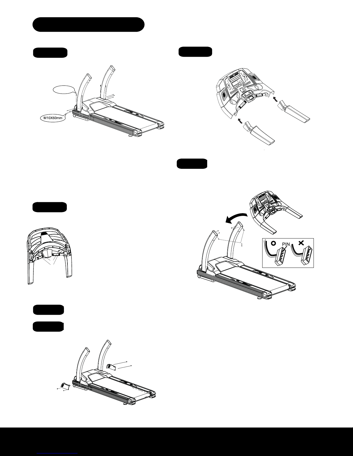
ASSEMBLY DRAWING
STEP 1- Assembly the Up-Right tubes
onto Base Frame.
STEP 2- Assembly the handle bars into
STEP 3- Screw on the M8x40mm bolt on
handle bars & tighten it.
STEP 6- Assembly the sides covers
of the Motor cover.
STEP 4- Assembly the console case onto
the Up-Right tubes.
(A) Plug & connect the cables on Right Up-Right tube with the related
Cables out from console bottom first.
Refer to attached drawing, put the console case (whole set) onto
the Up-Right tubes, screw on bolts #1 on both Up-Right tubes first and
check the screw holes on the sides of the Up-Right tubes, when you
find the screw holes on the side of Up-Right tube align to the screw holes
on the console case, put in M8x15mm bolts (4 pcs of each) & screw on
them.
Note :
1.Please do check & make the related cables organized to avoid
cable broken during assembly.
2.The connect plug PIN should not bent. to avoid improper
connection.
STEP 7- Tighten the bolts on Step 1 &
Step 4
(A) Refer to the attached drawing, first to
screw & tight the bolts #1 on handle bars,
then, to screw & tight the bolts #2
(A) Assembly the Left Up-Right tube onto the Left side of
The Base frame (no cable inside the Left Up-Right tube),
Use M6 hexagon wrench to screw on the M10x60mm
Bolts (3 pcs) & M10x20MM bolts (2 pcs), but not tighten it yet.
(B) There is a guide cable inside the Right side Up-Right tube
fix the (lower Console Cable) & (Ground Cable) from Base frame
onto this guide cable, then slide these cables from inside of
Right Up-Right tube from bottom to top, then fix the cables
On outside of the top Right Up-Right tube (ready for use later).
Assembly the Right Up-Right tube onto the Right side of
The Base frame. Use M6 hexagon wrench to screw on
the M10x60mm bolts (3 pcs) & M10x20MM bolts (2 pcs),
but not to tighten it yet.
(A)Screw & tighten the M4x15mm bolts and onto the side
motor covers.
M6x10mm bolts
M6X10mm
M4X15mm
M10X20
Refer to the attached drawing: Secure the handle bars onto
the upper console. Insert and tighten bolts as shown to the left
in diagram #1 and #2.
(A) Plug and connect the Console Cable and Ground Cable
from the right Up-Right tube to the cables from the Upper
Console: Do not “force” connection, make sure the pins line up
evenly. Failure to do so may cause the pins to bend which will
prevent the treadmill from working properly. Refer to attached
drawing. Once the cables are attached to each other, place
the entire Upper Console onto the Up-Right tubes. (Make
sure not to pinch Data Cables between Upper Console and
Up-Right tubes). Align the bolt holes from both Up-Right
tubes with the bolt holes from the Upper Console and insert
and tighten (4) M8x15mm bolts as shown in image to the right.
Again, make sure that cables are not pinched between any
parts of the treadmill.
#1
#2
ASSEMBLY INSTRUCTIONS
ASSEMBLY INSTRUCTIONS
ASSEMBLY INSTRUCTIONS